Design and Analysis of Suspension System of a
Student Formula Car
Abishek.R.K¹, Aswin Krishna.M¹, Balaguru.J¹
¹Third Year UG, Department Of Mechanical Engineering ,Kumaraguru College Of Technology, Coimbatore, Tamilnadu, India ¹
ABSTRACT: The objective of our paper is to design the whole suspension system which includes coil springs, control-arms and damper in the double wishbone system for student formula car. First based on the ride rate, wheel rate and motion ratio we calculate the spring rate. Then with the help of it we set the dimensions for the spring. Then CAD modelling of the spring is done using creo parametric. Then we sketch the a-arm by fixing the UCA, LCA axis, UBJ and LBJ points. Then required damper should be selected according to the spring stiffness. Then using MATLAB, system response is generated for the spring, damper and mass assembly. Then we do structural analysis for springs for control arms using ANSYS Workbench(15.6). At last the whole assembly is analysed for Multi Body Dynamics in Hyper works and results are checked.
KEYWORDS: Control arms, Upper control arm axis(UCA axis), Lower control arm axis (LCA axis), Upper ball joint
(UBJ), Lower ball joint(LBJ),Multi Body Dynamics in Hyper works.
І.INTRODUCTION
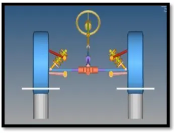
Suspension system is the one of the important system in vehicle. It supports the weight of the vehicle and provides the smooth ride. It allows rapid cornering without extreme body roll and keeps tire in firm contact with the roll and it also prevents excess body squat and body dive. It allows front wheel to turn side to side steering. It also works with the steering to keep the wheels in correct alignment. The basic parts of suspension system aarm (control arm) ,spring, damper ,knuckle etc. In this paper we have designed and analysed the a-arm, spring and whole assembly of the suspension system.
Figure 1:assembly of suspension system
II. DESIGN PROCEDURE FOR SUSPENSION SYSTEM
1. First of all we set the wheel track and wheel base according to the conditions in the sae rulebook. 2. Then we have to select the type of suspension system (eg: double wishbone).
4. Next, we have to set the ride frequency to calculate the ride rate, roll rate, etc.
5. After that, we have to calculate the spring rate with the help of motion ratio and wheel rate and the spring is designed with the help of spring rate.
6. Then we sketch the a-arm by fixing the UCA, LCA axis, UBJ and LBJ points to achieve the required anti-dive and anti-squat.
7. Then dampers are selected by selecting the right damping ratio which is suited for the stiffness of the springs. 8. Following that, FEA analysis is done for the springs and control arms and the results are checked.
9. The system response is generated for the mass, spring and damper assembly in MATLAB.
10. Then the whole assembly of the suspension system is checked for ride and roll analysis in Hyperworks.
III. SPECIFICATIONS OF THE CAR
Initially we have to set the specifications of our car like wheel base and track, Camber, Castor, Kingpin angle, etc.
Table 1: Specifications of the car
WHEEL BASE(mm) 1550
WHEEL TRACK FRONT(mm) 1250
WHEEL TRACK REAR(mm) 1200
CAMBER 1.5°
CASTOR 3.5°
KING-PIN ANGLE 4°
IV. CALCULATIONS IN THE SUSPENSION SYSTEM
Calculation of spring rate and weight distribution during cornering:
The front ride frequency is set to 2.8 Hz and rear is about 3 Hz. Now using these all other rates are found.
Krf= 4*π*π*(f2)*60/1000 = 18.57 N/mm; Kwf = KtKr/(Kt-Kr) = 22.8 N/mm,
Kwr = KtKr/(Kt-Kr) = 47.01N/mm; Motion ratio= 0.75 and
Spring rate SR= Kwf/(IR2)= 46.54 N/mm
Weight distribution:
W1=588.6 N, W2=588.6 N, W3= 882.9 N, W4= 882.9 N, CG height(h)=285 mm,
Cg to roll axis(H)= 240 mm α=-10 deg, R= 24.38 m, V= 77 kph, zrf=45
mm, zrr=55 mm,
Aα (Horizontal lateral acceleration) = v2/(rg) = -1.91g, Ay= A
αcosα-sinα = -1.706 g ,
W'=W(Aαsinα+cosα) = 3875.36 N
Effective front load W'f= W'*b/l= 1550.144 N , Effective rear load W'r= W'*a/l= 2325.216 N
Roll gradient= φ/(A*y) = -1.131 deg/g kφf= Krf*tf2/2= 14507.8 Nm/rad
kφr= Krr*tr2/2= 23018.4 Nm/rad Front roll rate distribution= 38.66%
Rear roll rate distribution=61.34% Front lateral load:
= -424.55 N
Rear lateral load:
= -758.97 N
Front load distribution= 35.87% Rear load distribution= 64.13%
Wfo= (W'f/2)+Wf = 1199.622 N
Wfi= (W'f/2)-Wf = 350.522 N
Wro=(W'r/2)+Wf = 1921.578 N
Wri=(W'r/2)-Wf = 403.638 N
Spring Calculations:
Total load= 300 kg; Front load(single wheel)= 60 kg; Assume spring index= 7
By iteration finally we get wire diameter d=10 mm and mean coil diameter= 70 mm
From Soderberg equation,
),
Fs= 1.45N=8*Pmax*D3*N/(G *d4) => N=6 , Nt=6+2=8
Solid length Ls=80 mm and Free length L = Ls+ δmax+ δallowance = 146.5 mm
Pitch= Free length/(Nt-1)= 20.92 mm
Stiffness K= =48.56 N/mm
Spring frequency= = 90.487 Hz
Control arms load calculations:
front load(single wheel)= 60 kg ; 2G force= 1177.2 N force at
knuckle point=1177.2/cos(3.36°) = 1179.227 N force at strut point =
1179.227/0.75 = 1572.303 N
Force along strut = 1572.303/sin(51°) = 2023.176 N
Total force on control arms =(1572.303 +1179.227) = 2751.53 N
Sprung and Un sprung calculations:
Front(single wheel):
Un sprung mass =16 kg, Sprung mass = 60-16 = 44 kg Rear(single
wheel):
Un sprung mass =18 kg, Sprung mass = 90-18= 72 kg
Total sprung mass = 232 kg Total un sprung mass = 68 kg
Sprung mass damping ratio = 0.5-0.7 (we take 0.7), Un sprung mass damping ratio = 0.3-0.5 (we take 0.5)
Front damping coefficient =578.403 kg/s, Front sprung frequency =(1/2π)*(KRf/ms)(1/2)= 3.084 Hz
Front un sprung frequency=(1/2π)*(Ks+Kt/mus)(1/2)= 20.487 Hz
V. GEOMETRICAL CONFIGURATIONS
For the control arms it is purely done by sketching with the help of LCA and UCA axis, UBJ and LBJ points and anti-dive and anti-squat. Then with that sketch we have to finish the CAD modelling of the control arms. Here, AISI 4130 is used as the material for control arms and chrome vanadium for springs.
Table 2:Geometrical configurations of spring
Suspension spring Front
Wire diameter (d) 10mm Outer diameter (D+d) 80 mm Free length(L) 146.5mm Pitch(p) 20.92mm
No of turns(n) 6+2=8
Figure 2 :Design of front and rear spring
Figure 3:Assembly of spring with damper
Table 3:Specifications of upper arm and lower arm
SPECIFICATIONS UPPER ARM LOWER ARM
Control arm top view angle(°) 58.82 56.12 Fvsa(Front view swing arm length) (mm) 262 266
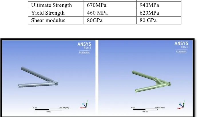
Table 4: Material properties for arm material and spring material
Figure 4:Design of upper and lower A-arm
VI. FINITE ELEMENT ANALYSIS
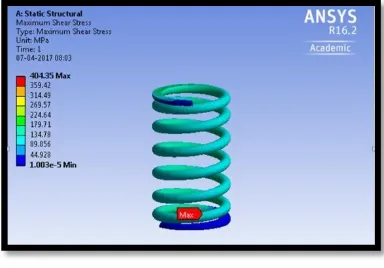
Springs:
Boundary conditions:
• One end is fixed.
• In other end required load is given.
Figure 6 :Deformation at maximum load and at pre-load condition.
Table 5:Summarized results from spring analysis
springs
Initial deformation (with driver weight) 13.219mm Deformation at maximum force 43.27mm
Actual deformation 43.27-13.219 = 30.051mm
Equivalent shear stress 404Mpa
Factor of safety 1.53
Control arms:
Boundary conditions:
• By assuming as cantilever beam the ends of a-arm which connects to frame is fixed.
• Required forces are given at knuckle point In x- axis:1200N(cornering force)
In y- axis: 600N(wheel loads) In z-axis:500N(braking force)
• In lower control arm addition to those forces, strut force (2024N inclined 47.3° to horizontal) is also acted.
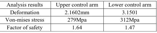
Table 6: Summarized results from control arm analysis Analysis results Upper control arm Lower control arm
Deformation 2.1602mm 3.1501 Von-mises stress 279Mpa 312Mpa
Factor of safety 1.64 1.47
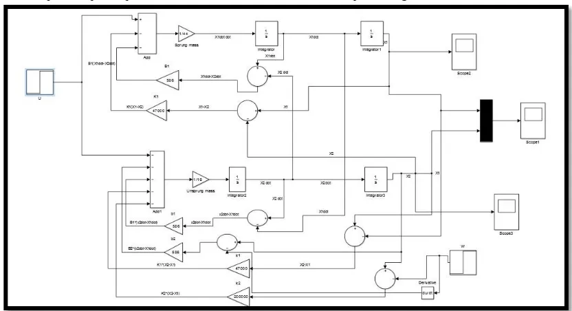
VII. MATLAB VIBRATION RESPONSE
The mass-spring-damper depicted in Figure 1 is modelled by the second-order differential equation
where is the force applied to the mass and is the horizontal position of
the mass.
Figure 9:Model of suspension system
With the help of scope, step and PID controller in MATLAB the response is generated.
Figure 11:Response time curve
Thus the nominal response meets the response time requirement in the above graph.
VIII. RIDE AND ROLL ANALYSIS
For the purpose of Ride and Roll analysis in Multi Body Dynamics, we have used Hyper Works in our project The graphs are plotted and the results generated are found to be appropriate.
Figure 12:Ride analysis of our assembly Figure 13:Roll analysis of our assembly
Graphs regarding ride analysis are:
Figure 14:Wheel vertical displacement graph Figure 15:Caster angle vs Time
Figure 16: Roll centre height vs Displacement
Graphs regarding roll analysis are:
Figure 18 :Roll angle ,track width graph
IX.CONCLUSION
First the wheel base and track, camber and castor angles in the car is set and then the wheel and spring rates are calculated. Then with those values springs and control arms are designed and structural analysis is done in springs and control arms. Along with this modal analysis in the springs is performed. Then the response is generated in MATLAB and multi body dynamics is performed in hyper works and graphs are generated and are found to be smooth. Thus the design and analysis of suspension system is completed.
ACKNOWLEDGMENT
I would like to thank Professor Dr.N.Sangeetha and Assistant Professor Manikanda Prasath and HOD of our mechanical engineering department, Kumaraguru College Of Technology, Coimbatore for their valuable support to fine tune and develop this project.
REFERENCES
[1] Race Car Vehicle Dynamics byWilliam F. Milliken, Douglas L. Milliken
[2] Bos P.C.M., “Design of a Formula Student Race Car Spring-Damper System”, 0576519 CST2010.024 [3] Gillespie T.D., “Fundamentals of Vehicle Dynamics”, Society of Automotive Engineers.
[4] http://nptel.ac.in/courses/107106080/
[5] Bhandari. V. B., “Design of Machine Elements”, 2010, TATA Mcgraw Hills.
[6] Mr. Amit A.Hingane Prof. S. H. Sawant Prof.S.P.Chavan Prof. A.P.Shah, "Analysis of Semi active Suspension System with Bingham Model Subjected to Random Road Excitation Using MATLAB/Simulink", IOSR Journal of Mechanical and Civil Engineering (IOSRJMCE) [7] W. Jianyu, L. Yutao, and H. Xiangdong, “Optimization of double wishbone independent suspension for FSAE racing car”, Machinery Design &