ISSN(Online): 2320-9801
ISSN (Print): 2320-9798
I
nternational
J
ournal of
I
nnovative
R
esearch in
C
omputer
and
C
ommunication
E
ngineering
(An ISO 3297: 2007 Certified Organization)
Vol. 3, Issue 9, September 2015
A Comparative Study of Robust Blind Image
Watermarking Scheme for Image
Authentication Using DNA Encoding, Optimal
Wavelet Basis & Discrete Wavelet Transform
Pearl Antonette Mendez
1, Rithu James
2M. Tech Student, Dept. of Electronics & Communication, Rajagiri School of Engineering & Technology, Kakkanad,
Cochin, Kerala, India1
Assistant Professor, Dept. of Electronics & Communication, Rajagiri School of Engineering & Technology, Kakkanad,
Cochin, Kerala, India2
ABSTRACT: The huge success of the Internet allows for the transmission, wide distribution, and access of electronic
data in an effortless manner. Content providers are faced with the challenge of how to protect their electronic data. With rapid development of information techniques and network, more and more bugs of traditional encryption techniques have appeared in digital media copyright protection. An efficient approach for copyright protection is the digital watermarking technique. In this paper, an algorithm is for hiding the complement of a DNA-encoded watermark
data into the 3rd level resolution of the wavelet decomposition of a true colour image. It applies a quantization operation
on the sorted detail coefficients for an enhanced invisible embedding. The extraction process is carried out blindly without the need to refer to the original host image. Also OWB technique is being used for image decomposition and the same algorithm is being used for watermarking.
KEYWORDS: DNA encoding; DWT; Multi-resolution decomposition; OWB; Watermarking;WPD
I. INTRODUCTION
The success of the Internet introduces a new set of challenging problems regarding security. Conventional cryptographic systems permit only valid key holders access to encrypted data, but once such data is decrypted there is no way to track its reproduction or retransmission. Therefore, conventional cryptography provides little protection against data piracy, in which a publisher is confronted with unauthorized reproduction of information. A digital watermark is intended to complement cryptographic processes. It is a visible, or preferably invisible, identification code that is permanently embedded in the data and remains present within the data after any decryption process. [1] A digital watermark is a kind of marker covertly embedded in a noise-tolerant signal such as audio or image data. It is typically used to identify ownership of the copyright of such signal. "Watermarking" is the process of hiding digital information
in a carrier signal; the hidden information should,but does not need to, contain a relation to the carrier signal. Digital
watermarks may be used to verify the authenticity or integrity of the carrier signal or to show the identity of its owners. It is prominently used for tracing copyright infringements and for banknote authentication.
II. RELATEDWORK
ISSN(Online): 2320-9801
ISSN (Print): 2320-9798
I
nternational
J
ournal of
I
nnovative
R
esearch in
C
omputer
and
C
ommunication
E
ngineering
(An ISO 3297: 2007 Certified Organization)
Vol. 3, Issue 9, September 2015
techniques. In blind schemes the embedding process is carried out in such a way that allows the hidden data to be extracted directly from the watermarked image without knowledge of the original one. On the contrary, in non-blind schemes the original cover is needed to reveal the hidden information. Obviously, blind techniques are preferred over the non-blind ones since they are more practical and reliable. [4] DWT has excellent spatial localization and multi-resolution characteristics, which are similar to the theoretical models of the human visual system. The original image is decomposed into four sub-band images by DWT: three high frequency parts (HL, LH and HH, named detail sub images) and one low frequency part (LL, named approximate sub-image). The detail sub-images contain the fringe information while the approximate sub-image is the convergence of strength of original image. Relative to the detail sub-images, approximate sub image is much more stable, since the majority of image energy concentrates here.
Therefore, watermark is embedded into approximate sub-image to gain a better robustness[5].According to [6], the low
frequency part concentrates the most energy of image, the amplitude of coefficient is larger than the one of detail
sub-graph.The high frequency part of discrete wavelets represents the edge, outline and texture information and other detail
information. Embedding watermark is difficult to be detected in these parts, but it is easy to be destroyed and has a poor stability after image processing.
III. DNAENCODING&DISCRETEWAVELETTRANSFORM
The hiding process is based on a quantization operation on the detail coefficients of the discrete wavelet transforms. In
an earlier work [7] the robustness of the quantization approach was proved to be efficient at the 3rd resolution level of
Haar wavelets. Here, we present an additional step concerning the embedded data. In this step, the watermark data are encoded into DNA alphabets for an added security level[8]. In fact, this encoding step can be replaced by any recent DNA-based ciphering technique.
III. A DNA Encoding
DNA is a double stranded structure consisting of four types of building blocks or nucleotides: adenine (A), guanine (G), thymine (T) and cytosine (C). In nature, these bases pair up in a unique complementary way, where A pairs with T and G pairs with C. Hence, a sequence of DNA base pairs can be viewed as a string made of these four characters such
as AAGTCGATCGATCATCGA. This “genetic code” is read and eventually translated by the cellular machinery to
form proteins in a long and complex process called Central Dogma[9]. The code is read and transcribed from the DNA into messenger RNA (m-RNA) three bases at a time. Each three adjacent mRNA (C, A, U, G) bases form a single unit known as a codon. This triplet code allows for a total of 64 different codons that are mapped to 20 different amino acids (the building blocks of proteins).
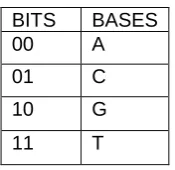
Fig 1: DNA coding of digital data
III.B. Watermarking algorithm using DWT
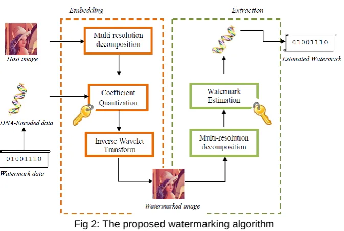
As shown in figure 2, the algorithm proceeds by first encoding the binary watermark into a DNA sequence. Next, the host image needs to be decomposed into multi-resolution levels using Wavelet (WLT) transform. The DNA encoded data are then embedded the Wavelet coefficients of the image using some quantization operation.
BITS BASES
00 A
01 C
10 G
ISSN(Online): 2320-9801
ISSN (Print): 2320-9798
I
nternational
J
ournal of
I
nnovative
R
esearch in
C
omputer
and
C
ommunication
E
ngineering
(An ISO 3297: 2007 Certified Organization)
Vol. 3, Issue 9, September 2015
Fig 2: The proposed watermarking algorithm
Finally, the embedded coefficients are inverse transformed resulting in the watermarked image. On the other side, the extraction process implements the same steps but in reverse order using the same secret key. Each one of these steps
are described in details through the following subsections. We refer to the original host image as I, the resultant
watermarked image as I’, the secret key as Key, and the watermark as W. The length of the watermark is denoted by Nw.
IV.EMBEDDING
Applying the Lth level discrete wavelet decomposition on an image results in 3L detail sub-bands and one
approximation image. Therefore, the kth detail coefficient of the image at the lth decomposition level will be denoted by
Ik,l (x, y) where k = h, v, d (corresponding to horizontal, vertical, and diagonal respectively) and the (x, y) coordinate
identifies the coefficient location in the specified sub-band. In addition, Ia,L (x, y) refers to the approximation
coefficients. Decomposing the host image at three levels using the Haar wavelet provides the optimal performance balancing between invisibility and robustness. The algorithm assumes that the order by which the coefficients will be selected for embedding depends on the value of a secret key. As long as the details of secret key are kept secret, an attacker will not be able to extract the watermark even if the details of the algorithm were exposed.
IV A. Embedding Process
1. Convert the watermark (W) from its binary form into a single-stranded chain of DNA nucleotides (WDNA) based on
some rule (such as the one shown in Fig. 3).
2. Initialize I’ to be I
3. Decompose I’ into the 3rd level of the Haar wavelet transform.
4. For each selected coefficient location (x, y); based on the randomness imposed by the key, do the following:
4.1. Sort the detail coefficients in ascending order such that: Ik1,3(x, y) ≤ Ik2,3(x, y) ≤ Ik3,3(x, y)
Where k1, k2, k3 are distinct and belong to the set { h, v, d}
4.2. If the range between Ik1,3(x, y) and Ik3,3(x, y) is below a given threshold value, skip the following steps and get
another coefficient location.
4.3. Embed the next base in WDNA as follows:
ISSN(Online): 2320-9801
ISSN (Print): 2320-9798
I
nternational
J
ournal of
I
nnovative
R
esearch in
C
omputer
and
C
ommunication
E
ngineering
(An ISO 3297: 2007 Certified Organization)
Vol. 3, Issue 9, September 2015
4.3.2 Let b’ be the complement of the base to be embedded.
4.3.3 Quantize the middle coefficient I’k2,3(x, y) as follows:
if (b’ equals A ) then I’k2,3(x, y) = I’k1,3(x, y)
else if (b’ equals C ) then I’k2,3(x, y) = I’k1,3(x, y) + Δ
else if (b’ equals G ) then I’k2,3(x, y) = I’k1,3(x, y) + 2Δ
else I’k2,3(x, y) = I’k1,3(x, y) + 3Δ
5. Apply the 3rd level inverse wavelet transform to get the watermarked image (I’).
The embedding procedure is done using the complement of the nucleotide base (b’) not the base itself (b). This step adds more security on the embedding process since the complementary rule can take many forms other the biological base pairing rule. Furthermore, this coding step can also be replaced by any suitable DNA-encryption algorithm.
V. EXTRACTION PROCESS
The steps of extraction process are exactly the inverse of those followed during the embedding phase. The objective is to reliably obtain an estimate (W’) of the original watermark (W) from a possibly distorted version of the watermarked image. In order to correctly extract the watermark data, the key is required to visit the exact locations of the coefficients
in the same order used for embedding. So, the extraction process starts by computing the 3rd level of the Haar wavelet
decomposition of watermarked image (I’). At each visited location, the inverse of the quantization process is carried out and the complement of the estimated nucleotide is appended to the watermark.
V.A The Extraction process- Algorithm
1. Decompose I’ into the 3rd level of the Haar wavelet transform.
2. Initialize WDNA to be an empty string
3. For each selected coefficient location (x, y); based on the randomness imposed by the key, do the following:
3.1. Sort the detail coefficients in ascending order such that: Ik1,3(x, y) ≤ Ik2,3(x, y) ≤ Ik3,3(x, y)
Where k1, k2, k3 are distinct and belong to the set {h, v, d}
3.2. If the range between Ik1,3(x, y) and Ik3,3(x, y) is below a given threshold value, skip the following steps and get
another coefficient location.
3.3. Extract the next base in WDNA as follows:
3.3.1. Find the value of Δ which is the difference between the largest coefficient and smallest coefficient divided by 3.
3.3.2 Estimate the embedded base (b) as follows:
if I’k2,3(x, y) lies near from I’k1,3(x, y) then b A
else if I’k2,3(x, y) lies Δ apart from I’k1,3(x, y) then b C
else if I’k2,3(x, y) lies 2Δ apart from I’k1,3(x, y) then b G
else b T 3.3.2 find b’, the complement of b
3.3.3 Append b’ WDNA
4. Convert (WDNA) into binary to get estimated the watermark (W’).
VI. WAVELET PACKET TRANSFORM & OPTIMAL WAVELET BASIS
Wavelet Packet Decomposition (WPD) (sometimes known as just Wavelet Packets or Subband Tree) is a wavelet transform where the discrete-time (sampled) signal is passed through more filters than the discrete wavelet transform (DWT). In the DWT, each level is calculated by passing only the previous wavelet approximation coefficients through discrete-time low and high pass quadrature mirror filters. However, in the WPD, both the detail and approximation
coefficients are decomposed to create the full binary tree. In DWT, only the approximated detail of the image is being
ISSN(Online): 2320-9801
ISSN (Print): 2320-9798
I
nternational
J
ournal of
I
nnovative
R
esearch in
C
omputer
and
C
ommunication
E
ngineering
(An ISO 3297: 2007 Certified Organization)
Vol. 3, Issue 9, September 2015
employed[10]. The reason behind selecting the OWB packet is its dynamic decomposition nature in forming the
subbands. Shannon entropy cost function is chosen and implemented for obtaining the OWB.
VI.A Extracting Optimal wavelet basis
Step 1: Decompose the parent node into four subbands (children node) and compute their shannon entropy.
Step 2: If sum of entropies of the children node is greater than that of the subband entropy (cost function), then retain the parent node and eliminate the children node. Otherwise retain both parent and children nodes.
Step 3: If there are no nodes to split, the process of extracting the OWB reaches the end
VII.SIMULATION RESULTS
The simulation studies involves decomposing the host image using two techniques, ie discrete wavelet transform and optimal wavelet basis and watermarking process is being carried out by first DNA encoding the complement of the watermark and embedding it into the decomposed form of the source image. Watermark is being retrieved in both cases using the extraction process. Both the algorithms were being implemented using MATLAB.
The DNA encoding is being done by coding the binary values as shown in Fig1. The embedding and extraction process is being done as shown in Fig 2. The host image is being decomposed, and two different watermarks are being embedded, they are then retrieved and the PSNR value is being calculated using inbuilt function. The baboon image is being used as the host image for watermarking using the DWT procedure.
The third level decomposition of the host image is being used for watermarking. Embedding of the watermark is being done in horizontal, vertical and diagonal detail coefficients. The OWB is being extracted by using the Shannon entropy as the cost function. The entropy values are different for each image and hence the location of coefficients in which the watermark will be embedded will also be different. Here Shannon entropy was being calculated for three test images, Lena, Baboon and Pepper. For the Lena image, the parent and children nodes are retained for the Diagonal detail (Fig 5(b)). The parent & children node for the vertical detail are being retained in the baboon image (Fig 6(b)). As shown in fig 7(b), for the pepper image, parent and children node are being retained for the horizontal detail.
Entropy of parent node
Sum of entropies of children node
conclusion Lena image
-1.8153e+010 -2.0594e+010 Retain the parent node and children Whole image
-2.0568e+010 -2.2926e+010 Retain parent node and children Approximated
-6.9908e+006 -6.4889e+006 Retain parent node, eliminate children Horizontal detail
-1.7673e+007 -1.6936e+007 Retain parent, eliminate children Vertical detail
-1.4703e+006 -1.5470e+006 Retain parent node and children Diagonal detail
Tab1: Entropy distribution for Lena image
ISSN(Online): 2320-9801
ISSN (Print): 2320-9798
I
nternational
J
ournal of
I
nnovative
R
esearch in
C
omputer
and
C
ommunication
E
ngineering
(An ISO 3297: 2007 Certified Organization)
Vol. 3, Issue 9, September 2015
(a) (b) Fig 3: (a) Lena image (Host 1), (b) Extracted OWB of Lena image
Similarly, entropy distribution was being found out for the Baboon image & the Pepper image and the OWB was being extracted.
(a) (b)
ISSN(Online): 2320-9801
ISSN (Print): 2320-9798
I
nternational
J
ournal of
I
nnovative
R
esearch in
C
omputer
and
C
ommunication
E
ngineering
(An ISO 3297: 2007 Certified Organization)
Vol. 3, Issue 9, September 2015
(a) (b)
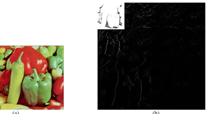
Fig 5: (a) Pepper image (Host 3), (b) Extracted OWB of Pepper image
Fig 5 (a) and 5(b) shows the Pepper image and its extracted OWB based on the entropy distribution respectively. Figures 6 and 7 shows a comparison of the original watermark image and the retrieved ones. Figures 6(b) and 7(b) shows the retrieved watermarks when the host image was decomposed using DWT.
(a) (b) (c)
Fig6: (a) Watermark image (b) Watermark retrieved after image decomposition using DWT (c) Watermark retrieved using OWB decomposition
Figures 6(c) and 7(c) describes the retrieved watermarks after image decomposition using OWB. Clearly, from the figures, OWB image decomposition gives a better copy of the embedded watermark after retrieval when compared to DWT.
(a) (b) (c)
ISSN(Online): 2320-9801
ISSN (Print): 2320-9798
I
nternational
J
ournal of
I
nnovative
R
esearch in
C
omputer
and
C
ommunication
E
ngineering
(An ISO 3297: 2007 Certified Organization)
Vol. 3, Issue 9, September 2015
TECHNIQUE BABOON LENA
DWT 10.7897 7.4342
OWB 28.3421 24.8203
Tab 2: PSNR comparison for two host images using both the image decomposition techniques
Table 2 shows the PSNR comparison for two test images, Baboon & Lena which were decomposed using DWT and OWB respectively. PSNR was almost thrice for OWB image decomposition when compared to DWT decomposition.
VIII.CONCLUSION
The simulation results showed that the OWB extraction resulted in a better PSNR when compared to the DWT decomposition since in OWB, all the detail coefficients are also decomposed and they are retained according to the cost function which is Shannon entropy in this case. The advantage of OWB is that the image information will be distributed to fewer coefficients and they will have a higher value than the noise coefficients. So by using a threshold value, the information coefficients can be extracted easily. The entropy distribution will not be the same for all images and hence the subbands which are to be retained will be different for different images.
REFERENCES
[1] Ingemar J. Cox,Joe Kilian, F. Thomson Leighton, and Talal Shamoon, “Secure Spread Spectrum Watermarking for Multimedia”, IEEE transactions on image processing, vol. 6, no. 12, DECEMBER 1997, pp 1673-1687
[2] Teruya Minamoto , Kentaro Aoki, "A blind digital image watermarking method using interval wavelet decomposition," International Journal of Signal Processing, Image Processing and Pattern Recognition, vol. 3, no. 2, pp. 59-72, 2010.
[3] R. G. van Schyndel, A. Z. Tirkel, and C. F. Osborne, “A digital watermark,” Proc. IEEE Int. Conf. Image Processing, vol. 2, pp. 86–90, 1994.
[4] Safwat Hamad & Amal Khalifa, “Robust Blind Image Watermarking using DNA encoding and Discrete Wavelet Transforms”, 8th
International conference on computer engineering and systems (ICCES), pp221-227, 2013
[5] Mayank Awasthi1 and 2Himanshi Lodhi, “Robust Image Watermarking based on Discrete Wavelet Transform, Discrete Cosine Transform & Singular Value Decomposition”, Advance in Electronic and Electric Engineering, Vol 3, No 8, pp. 971-976, 2013.
[6] Gursharanjeet Singh Kalra, Dr. Rajneesh Talwar & Dr. Harsh Sadawarti, “Robust Blind Digital Image Watermarking Using DWT and Dual Encryption Technique”, Third International Conference on Computational Intelligence, Communication Systems and Networks, pp 225-230, 2011.
[7] Safwat Hamad, Amal Khalifa, "Quantization-based Image Watermarking using multi-resolution wavelet decomposition," The Egyptian Computer Science Journal (ECS), vol. 37, no. 3, pp. 26-36, 2013.
[8] Safwat Hamad & Amal Khalifa, “Robust Blind Image Watermarking using DNA encoding and Discrete Wavelet Transforms”, 8th
International conference on computer engineering and systems (ICCES), pp221-227, 2013
[9] A. Ghosh, M. Bansal, "A glossary of DNA structures from A to Z," Acta Crystallographica Section D: Biological Crystallography Vol.59, no. 4, pp. 620-626, 2003.
[10] Abdolhossein Fathi and Ahmad Reza Naghsh-Nilchi, “Efficient Image Denoising Method Based on a New Adaptive Wavelet Packet Thresholding Function”, IEEE Trans on image processing, VOL. 21, NO. 9, Sep 2012
BIOGRAPHY
Pearl Antonette Mendez is a Post Graduate (MTech) student in the Department of Electronics & Communication