Development of Arduino Based Flow Control
System Implenting Fuzzy with PID controller
Godhini Prathyusha
1B.Ramamurthy
21 Research Scholar, Dept. Instrumentation & USIC, Sri Krishnadevaraya University, Anantapur , A.P, India 2 Professor, Dept. Instrumentation & USIC, Sri Krishnadevaraya University, Anantapur , A.P, India
ABSTRACT: The aim of the flow control is to control the flow rate and level of the tank in a system up to delimitated value, afterward hold this it at that level and flow rate of liquid of pipe in insured manner. Fuzzy with PID controller (FPID[1]) is the best way in which this type of control can be accomplished by controller. Here we have developed flow control system using FPID[2]. The desired response of the output can be guaranteed by the feedback controller.
KEYWORDS: Arduino Mega2560 microcontroller; Flow sensor; FPID
I. INTRODUCTION
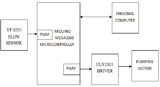
The total system can be developed by implementing software FPID, mainly it reduces the hardware complexity[3]. In this system, set point of the flow is given by the programmer using GUI.YF-S201 flow sensor sense the liquid flow rate of pipe which controls the total system using Arduino mega2560 microcontroller.
II. PROCEDURE
The flow measurement and control system is developed by using flow sensor,the output of sensor which is in the form of pulses is given to the Arduino Mega2560 microcontroller implementing FPID logic the PWM of the controller is given the signal for pumping motor through ULN2003 current driver.
A. YF-S201 HALL EFFECT WATER FLOW METER / SENSOR
Fig.2 Flow sensor
This sensor placed in line with the water line and contains a pinwheel sensor to measure how much liquid has pumped through it. There's an integrated magnetic hall effect sensor that outputs an electrical pulse with every revolution. The hall effect sensor is sealed from the water pipe and allows the sensor to stay safe and dry.The sensor consists of three wires.They are Red wire : +5V,Black wire : GND,Yellow wire : PWM.Hall-effect transistors also can be used. These transistors change their state when they are in the presence of a very low strength (on the order of 25 gauss) magnetic field. By counting the pulses from the output of the sensor, we can easily calculate water flow. Each pulse gives approximately in milliliters and the pulse rate does vary a bit depending on the flow rate, fluid pressure and sensor orientation. It will need careful calibration if better than 10% precision is required.YF-S201 Water Flow Sensor can be used to measure the liquid flow in both industrial and domestic applications. This sensor basically consists of a plastic valve body, a rotor , a hall effect sensor, inlet and outlet . The pinwheel rotor rotates when water or liquid flows through the valve and the speed of sensor will be directly proportional to the flow rate. The hall effect sensor will provide an electrical pulse with every revolution of the pinwheel rotor. This water flow sensor module can be easily interfaced with Arduino Mega2560 microcontroller Connect the PWM output of this module to interrupt pin of microcontroller unit and count the number of pulses or interrupt per unit time. The rate of water flow will be directly proportional to the number of pulses counted. The pulse signal is a simple square wave so its quite easy to log and convert into liters per minute using the following formula.
Pulse frequency (Hz) / 7.5 = flow rate in L/min eq. (1)
B. Implementing the FPID
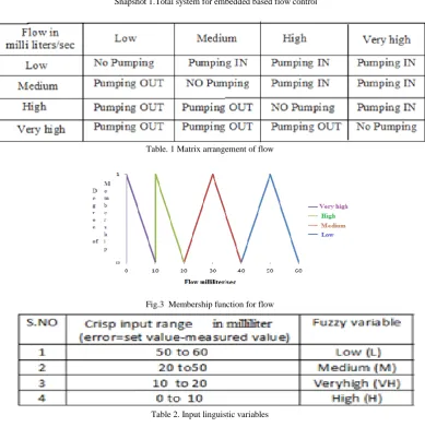
Depending on the size of pumping pipe line which is placed inline with the flow sensor , the number of electric pulses given by the sensor is vary.In this work,we use the pipe line pumps the water or liquid 500ml of unit second.It means approximately 10ml of liquid which moved through the sensor gives a single pulse as a output.By using software [4] Fuzzy with PID controller (FPID) the flow and level can be controlled at a time.Fuzzification process, ruleset of the variables and defuzzification[5],[6] of flow control is same as which is applied to the level control but the different units are used for individual specification.The PWM of controller can be drive the pumping motor through ULN2003 driver.
C. FUZZY RULESET
If flow range is 40 to 60 ml/sec, the FPID 1 is applied .i.e., the proportional constants Kp,Ki ,Kd of set 1 will be
executed in the program.
If flow range is 20 to 40ml/sec, the FPID 2 is applied .i.e., the proportional constants Kp,Ki ,Kd of set 2 will be
executed in the program.
If flow range is 10 to 20 ml/sec, the FPID 3 is applied .i.e., the proportional constants Kp,Ki ,Kd of set 3 will be
If flow range is 0 to 10 ml/sec, the FPID 4 is applied .i.e., the proportional constants Kp,Ki ,Kd of set 4 will be
executed in the program.
Snapshot 1.Total system for embedded based flow control
Table. 1 Matrix arrangement of flow
Fig.3 Membership function for flow
Table.3(a) Deffuzification
Table.3(b) Output linguistic Variables
III. RESULTS
The results can be represented in the GUI window application using processing software .Fig.1 shows the continuous maintenance of the flow rate up to fixed level is reached.Fig.2 shows the time response of flow rate implanting FPID from 80ml t0 10ml of flow rate.
Fig.5 GUI for time versuss flow rate
Table.4 Comparison different algorithms
IV. CONCLUSIONANDFUTUREWORK
The design of Fuzzy with PID flow controller with active rule selection mechanism. The proposed system is tested in real time environment and the output performances are evaluated. In this system which is key point to reduce the cost by implementing software algorithm. We have successfully experiment this system in lab and therefore proposed a web based flow monitoring and controlling network with flexibility, further extension of this system is to control from any place via internet even with different type of devices. This could have a substantial benefit from this research work for efficient management of liquid flow.
REFERENCES
1. R.Arulmozhiyal and K.Baskaran, “Implementation of Fuzzy PI Controller for Speed Control of Induction Motor Using FPGA”, Journal of Power Electronics, Vol.10, No.1, Jan 2010, pp.65-71
2. Seema Chopra, R Mitra and Vijay Kumar, “A robust International IEEE Conference Intelligent Systems, 2006, pp. 300-305. 3. K J Astrom and T Hagglund,,” Control“ThefutureEngineeringofPID - Practcontr1175.
4. William H. Woodall, October 2000 "Controversies and Contradictions in Statistical Process Control", Journal of Quality Technology, Vol.32, No.4, pp.341-350.
5. Douglas C, Montgomery and Bert Keats J, George C. Runger and William S. Messina, April 1994 "Integrating Statistical Process Control and Engineering Process Control", Journal of Quality Technology, Vol.26, No.2.
BIOGRAPHY
Godhini Prathyusha is doing P.hd in the Department of Instrumentation and USIC, Sri Krishna Devaraya university ,Anantapur. She also working as a Teaching assistant in the Department of Instrumentation and USIC, Sri Krishna Devaraya university , anantapur, AndhraPradesh, India. She having six years of teaching experience. Her area of interest are Network and Mobile Communications, network security systems, industrial automation,Instrumentation and embedded systems.