Implementation of Domain Integral Approach for J Integral Evaluations
Carlos Cueto-FelguerosoTecnatom S.A., San Sebastifin de los Reyes (Madrid), Spain A B S T R A C T
This paper presents an implementation of the Domain Integral Approach for calculation of the J integral. The method has been programmed by way of a series of sub-routines of the ANSYS Finite Element program, using its internal APDL programming language. This allows the J integral to be calculated by post-processing the results of a stress calculation from the program itself. Also analyzed are the results of application to specific cases, including comparisons with the results obtained by applying other methods to these same cases.
I N T R O D U C T I O N
In a two-dimensional field, the J integral is defined by means of a line integral. In the context of calculations using the Finite Element Method, it is preferable to perform integration with respect to an area, which is simply a natural extension of the integrations performed on each finite element during generation of the matrix of the element. D E F I N I T I O N OF J I N T E G R A L
In the case of a two-dimensional, non-linear elastic solid, and under the hypothesis of small strains and with body forces being neglected, the J integral is defined as follows [ 1 ]:
(1)
where: F
n i a U
uj ds W
is any contour surrounding the tip of the crack, moving in an counter-clockwise direction from the lower edge of the crack to the upper edge (Figure 1).
is the outward normal to F. is the stress tensor. is the displacements vector.
is the increment of arc length along F. is strain energy density, defined as:
W(eij ) = f~'J %de O. (2)
,,10
x a
£
!
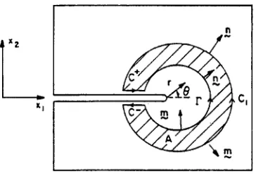
Fig. 1. Coordinates at crack tip.
E X P R E S S I O N OF D O M A I N I N T E G R A L IN T W O D I M E N S I O N S I N C L U D I N G T H E R M A L STRAINS AND BODY FORCES
Let us consider an annular region A around the tip of a crack (Figure 2). Let C = C~ + C + - F + C- be the closed contour surrounding region A and m be normal towards the outside of C. Consequently, m - -n at F and m - n at C~.
SMiRT 16, Washington DC, August 2001 Paper # 1355
e
If thermal strains act on the structure, the total strains may be expressed as the sum of an elastic part eU, a plastic part eP and a thermal part. In this case, the mechanical strain energy is defined as follows [2]"
~0 g'n
W(13~/, 0) = 'J crude/j m (3)
where the mechanical strains are given by:
m e P - c~0~5/j (4)
~U = ~/J + ~o
where c~ is the coefficient of thermal expansion and 0 is the temperature above the reference temperature. The expression of J integral is as follows [2]:
I t~U j
J = I A CO" cgx 1
L[ °
J&:J
f J-~l ql d A - Ic++c-tjUj'l ql dS
(5)
where q~ is a sufficiently smooth function in A, which is equal to the unit in F and vanishes in C~.
rl
x 2
Fig. 2. Annular region A and associated contours.
In the absence of thermal strains, body forces and/or tractions at the faces of the crack, Eq. (5) reduces to the expression given by de Lorenzi [4].
Function q~ may be interpreted as the imposition of a unit translation in direction x~ with respect to the points on line F, while the points on line Cl to remain fixed. Consequently, this calculation approach to J integral is similar to a virtual crack extension technique.
Eq. (5) allows J integral to be evaluated as an area integral in region A that may be performed using the same integration procedures as applied in obtaining the stiffness matrix in the Finite Element Method. Analogously, the contribution made by the tractions at the faces of the crack may be evaluated by applying the normal integration procedures for pressures in this method. In short, this formulation is a natural extension to the Finite Element Method.
In the context of finite element calculations, F is normally the arc formed by the tip and the faces of the crack. In the presence of body forces, thermal strains and/or tractions on the crack faces, domain A should contain the tip of the crack (r ~ 0 +, Figure 2) [3]. By making C1 coincide with the contour of different regions surrounding the tip of the crack, J integral may be calculated in different domains, and just as the J integral defined by Eq. (1) is independent of the integration path, that calculated by Eq. (5) is independent of the integration domain.
For the axisymmetric case, the J integral is as follows:
j = l..~. IA {(cYDUv'r-WSrf~)q'f~ +(cxtr(~)O'r- fvUv'r)q}rdA
ra
1
c** ~ - W
q dA + m
++c- tvUv'rq r dC
r a
r
r a
(6)where:
is the radial distance to the point of integration. is the radial distance to the tip of the crack.
Indices 13 and ~, take the values of the coordinates r and z.
FORMULATION OF DOMAIN INTEGRAL APPROACH
Coordinates and Functions
Inside isoparametric finite elements, coordinates Xl, X2 and displacements Ul, U2 are expressed as follows [5-
6]:
X i = £ N I (~, 1]) Xii (7a)
I=1
U i "- £ N I (~, 1"1) UiI (7b)
1=1
where
n the number of element nodes. Xi~ the xi coordinates of the nodes.
U~ the u~ displacements of the nodes. Ni(~,rl) the shape functions of the element. ~, 1] the parametric coordinates of the element.
The derivatives of the displacements ui in an element are calculated by applying the chain derivation rule:
aui 0N..__..L
-" L UiI (8)
&J
Z=l a~k &J
where
O~k/aXj
is the inverse Jacobian matrix of coordinates transformation (7a). Analogously, function q~ may be expressed as followsn
ql = Z NI(~"q) Qll
(9)I=1
where Ql~ are the values of ql at the nodes.
The gradient of ql in an element is calculated by applying the same derivation method as is applied to displacements.
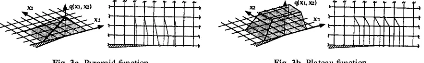
Function q~ should be specified at all the nodes within the integration domain. The shape of this function is arbitrary, although it should have correct values at the boundaries (in this case, on curves C~, F and the faces of the crack). Figures 3a and 3b represent two examples of ql functions commonly used for two-dimensional problems [2]. As will be seen in the following section, the calculated values of J integral are relatively insensitive to the shape of function q~.
Fig. 3a. Pyramid function. Fig. 3b. Plateau function.
Shape Functions
The shape functions for an isoparametric quadrilateral of the second order (8 nodes) are as follows:
comer nodes
midside nodes
1 2
N I
= ~-(1-~ )(1 +~lqi)
NI = 1 ( 1 - ~
I)(l
+ ~12)Z
~i = 0 (lOb)
q I = 0
(lOc)
Triangular elements of the second order (6 nodes) are used to model the first row of elements around the crack tip, their shape functions being as follows:
- corner nodes
N I = (2L I - 1)L I
(11 a)midside nodes
N I = 4LjL K
where I ~J, K (1 lb)The area coordinates are not independent one from another, since at any point of the element their sum must be equal to the unit. In order to overcome this difficulty, two independent variables are defined, as follows:
=LI 11 = L2
1 - r l - ~ = L 3
(12)
The replacement of variables having been performed, the following operations are analogous to those of the quadrilateral element.
Numerical Integration
Eq. (5) may be evaluated numerically as the sum extended to all the finite elements in region A of the individual contributions of each element, in accordance with the following expression:
J=Z~pl
o'Uj ,l-W~li)ql,i]det(Oxk];
j
Io~kjjpWp
+ Z Z
~iiO fjuj ,I
,1- )ql ]de t 0x~Wp
A = A p=l p
C + + C -
(13)
The quantities shown inside square brackets { }p are evaluated at the
ng
points of integration or the Gaussian points, and Wp are the corresponding weighting factors. The term due to traction at the crack faces may be evaluated using the equivalent nodal forces and the values ofOu~/Ox~
at the nodes, or an integration process for pressures at the boundary.For the axisymmetric case, the discretized expression of Eq. (6) is as follows:
J = ~ ' - Z Z a A p=l [(~13vuv,-14zS,'f~)q,f r
~]det(axk l
~, O~k ) r pWp- 1 Z
ra A = [(13{, tr(a)O r, - fvUv,r) q]det(Oxk ~
~,O~k ) r.,pWp_ 2 o¢¢ - W det
q W p - - - Z{tvUv,rq
r a =
r
~,O~k, )
P r a C++C_D E M O N S T R A T I O N CASES
The calculation process described has been implemented in a series of post-processing sub-routines of the ANSYS program and written in its internal programming language APDL (ANSYS Parametric Design Language).
In this way, calculation of the integral is carried out as a post-process of the stress calculation within the ANSYS program itself.
Cases in the Elastic Range
/ / / / 1 / / ~ / /
. . . 0 0 0 0 ~1
= w )
Ix, l
2 _
4-0--~ x,
a/W= 0.5
L/W= 2.0
.~.-..--W ...-..~
) o o o £x
1 / 7 f l • / / I /
Fig. 5. Plate with edge crack subjected to a temperature distribution.
The first case analyzed consists of a plate under plane strain conditions, with an edge crack subjected to a linear temperature distribution and whose longitudinal displacements are constrained at the ends [2], (Figure 5).
The stress in the plate in the absence of a crack is as follows: Eo~0
~o = e (15)
( l - v )
where E = 210000 MPa and (x = 12.10 "6 ° c ' l .
: :~
T - .... -
- 4 - . . . !
+ ~ . + ... ! -.~+ . . . .
.+ ... : ...
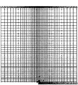
Fig. 6. Finite element mesh.
The finite element mesh has been developed making use of the condition of symmetry with respect to the plane of the crack (Figure 6). It is made up of 1618 isoparametric elements of the second order and 5003 nodes. Triangular elements (one every 15 °) have been used in the first row of elements around the tip of the crack. The size of these elements is equivalent to
a/40,
being a the depth of the crack.The J integral has been calculated in the regions represented in Figure 7, which have been denominated in increasing order of size, making use of the plateau and pyramid type q~ arbitraryfunctions.
Given that the load applied is low, and with a view to achieving a better comparison with the solutions available in the literature, the stress intensity factor has been calculated on the basis of the values of J integral using the relationship"
!
J EKj = 1[ (16)
l _ v 2
V
Finally, the stress intensity factor has also been calculated by means of the ANSYS KCALC command, which is based on an algorithm that uses the displacements around the tip of the crack. For this purpose, the elements of the first row around the tip of the crack have been modified by displacing the midside nodes at ¼ from the tip.
i i
l
J
I !
Fig. 7. Regions of integration on the finite element mesh.
The results are summarized in Table 1. This shows that with the exception of Region 1, formed by the first row of elements around the crack tip (in which logically only pyramid type distribution is applicable), the values calculated for J integral do not show significant differences from one region to the next, nor as a result of using a plateau or a pyramid type distribution. For example, the result in Region 3, with a pyramid distribution, is almost identical to that found in Region 4 and subsequent regions, with plateau distributions. Naturally, the values of Kj follow the same pattern as those of J.
T a b l e 1. Calculated values of J integral for the case of a plate subjected to a linear temperature distribution.
Region P M
1
2 3
4 5 6 7 8 9 KCALC
o g a / E
Kj
0,213726 0,273422 0,199033 0,263856 0,198631 0,263590 0,198634 0,263592 0,198628 0,263588 0,198626 0,263586 0,198624 0,263585 0,198622 0,263583 0,198622 0,263583 0,263120
The second example of application is the same plate but subjected to a remote uniform tension. This case is well known and different engineering calculation methods exist for it.
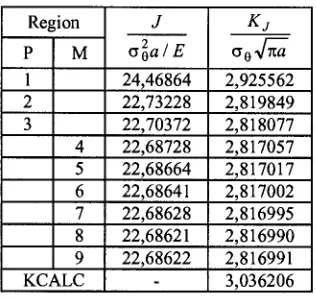
The results obtained are summarized in Table 2.
T a b l e 2. Calculated values of J integral for the case of the plate subjected to uniform remote stress.
Region P M
1
2 3
4 5 6 7 8 9 KCALC
o ~ a l E
K j
24,46864 2,925562 22,73228 2,819849 22,70372 2,818077 22,68728 2,817057 22,68664 2,817017 22,68641 2,817002 22,68628 2,816995 22,68621 2,816990 22,68622 2,816991 3,036206
C a s e s in the E l a s t i c - P l a s t i c R a n g e
For the analysis of these cases, consideration has been given to the possibility of approximating the uniaxial stress-strain curve of the material by a Ramberg-Osgood law.
¢ / n
s o o m = ~ + 7
So o0 t o 0 / (17)
where o0 = 420 MPa, So = o0/E = 0,002, n = 10 y 7 = 1. The yield criterion used has been that of von Mises, and isotropic hardening has been assumed. The stress-strain curve was approximated by various linear sections.
The temperature gradient applied to the plate was increased until the thermal strain s0 reached values of g0 and 260 respectively.
The values obtained are summarized in Table 3, where it may be seen that the normalized values of J integral maintain the same pattem as in the case of low load, although they are somewhat more sensitive to the size of the integration region. It should also be pointed out that in those regions whose boundaries are further from the tip of the crack, the value of J integral increases with respect to that of the midside regions, which might be due to the boundaries of the former being relatively close to the edges of the plate.
T a b l e 3. Calculated values of J integral for the case of the plate subjected to a high temperature gradient.
Region
P M
1
2 3
, 4
5 6 7 8 9
o ~ a / E e 0 ~ 0 = 1 s 0 ~ 0 = 2
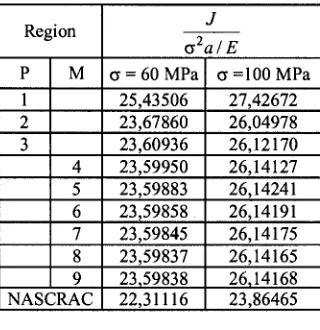
Finally, with a view to contrasting the methodology described here to others existing in the literature, the case of the plate subjected to the action of a relatively high uniform stress has been analyzed, and the results have been compared to those obtained by the NASCRAC program [7].
Table 4 shows that the agreement is fairly satisfactory.
Table 4. Calculated values of J integral for the case of the plate subjected to a high remote uniform tension.
Region
P M
1
2 3
4 5 6 7 8 9 NASCRAC
o2a/E
c = 6 0 M P a c = 1 0 0 M P a 25,43506 27,42672 23,67860 26,04978 23,60936 26,12170 23,59950 26,14127 23,59883 26,14241 23,59858 26,14191 23,59845 26,14175 23,59837 26,14165 23,59838
22,31116
26,14168 23,86465
CONCLUSIONS
The sub-routines of the domain integral approach for J integral allow for fairly efficient post-processing of the results of a calculation using the Finite Element Method.
The values obtained for the J integral show a fair amount of independence from the integration regions and weighting functions q~, and also compare favourably to those obtained using other methodologies.
R E F E R E N C E S
[1] F.Z. Li, C.F. Shih and A. Needleman, "A comparison of methods for calculating energy release rates",
Engineering Fracture Mechanics 21, 1985, pp 405-421.
[2] C.F. Shih, B. Moran and T. Nakamura, "Energy release rate along a three-dimensional crack front in a thermally stressed body", International Journal of Fracture 30, 1986, pp 79-102.
[3] T. Nakamura, C.F. Shih and L.B. Freund, "Computational methods based on an energy integral in dynamic fracture", International Journal of Fracture 27, 1985, pp 229-243.
[4] H.G. deLorenzi, "Energy release rate calculations by the finite element method", Engineering Fracture
Mechanics 21, 1985, pp 129-143.
[5] ANSYS Theory Manual, Version 5.6.