Server and M anagem ent S y stem
D esign for
a D istrib u ted VoD Service
A thesis subm itted for the degree of D octor of Philosophy
in Electronic and Electrical Engineering
January 2000
A ikaterini Papanikolaou
UCL
ProQuest Number: U643534
All rights reserved
INFORMATION TO ALL USERS
The quality of this reproduction is dependent upon the quality of the copy submitted.
In the unlikely event that the author did not send a complete manuscript and there are missing pages, these will be noted. Also, if material had to be removed,
a note will indicate the deletion.
uest.
ProQuest U643534
Published by ProQuest LLC(2016). Copyright of the Dissertation is held by the Author.
All rights reserved.
This work is protected against unauthorized copying under Title 17, United States Code. Microform Edition © ProQuest LLC.
ProQuest LLC
789 East Eisenhower Parkway P.O. Box 1346
S tatem ent o f originality
The work presented in this thesis was carried out by the candidate. It has not
been presented previously for any degree, nor is it at present under consideration
by any other degree awarding body.
Candidate:
Aikaterini Papanikolaou
Diredtor of studies:
Statem ent o f A vailability
1. I authorise th at the thesis presented by me in 2000 for examination for
the M Phil./PhD degree of the University of London, shall, if a degree is
awarded, be deposited in the University of London Library and in the
library of the appropriate College and th at, subject to the conditions set
out in paragraph 9.2 (d) below, my thesis be made available for public
reference, inter-library loan and copying.
2. I authorise the University of London to supply a copy of the abstract of my
thesis for inclusion in any published list of theses offered for higher degrees
in British universities or in any supplement thereto, or for consultation in
any central file of abstracts of such theses.
3. I authorise the University of London to make a microfilm copy of my thesis
for the purposes of inter-library loan and the supply of copies.
4. I understand th at before my thesis is made available for public reference,
inter-library loan and copying, the following statem ent will have been
included at the beginning of my thesis: The copyright of this thesis rests
with the author and no quotation from it or information derived from it
may be published without the prior written consent of the author.
5. I authorise the University of London to make a microfilm copy of my thesis
in due course as the archival copy for permanent retention in substitution
for the original copy. I warrant th a t this authorisation does not, to the
best of my belief, infringe the rights of any third party.
6. I understand th a t in the event of my thesis being not approved by the
Candidate:
A bstract
In this thesis a study on the design and performance of a distributed VoD
service is presented.
In the first chapter a general introduction to the thesis is provided.
In the second chapter we provide a review to the enabling technologies for
multimedia services and specifically for VoD. We review netwotk, transport and
delivery standards.
In the third chapter we present an overview of the most im portant VoD
trials and an analysis on the composing components of the VoD service.
In the fourth chapter we present VoD service designs from the bibliography,
th at support and promotethe idea a distributed service provision system.
In the fifth chapter we present our design for a VoD server, supporting mass
and interactive user connections, based on a two-tier control system. The first
tier is based on staggered multicast at very short time intervals and processes
normal connection flow and the second tier, provides the control for the user
defined actions.
In the sixth chapter we present our design for the VoD server management
system. Our system is a heuristics based one, it uses as little network status
information as possible and makes decisions based on the current popularity
rates it is receiving from the network. The movies are separated into classes
depending on popularity and treated accordingly.
In the seventh chapter we present the simulation network we used in our
study. The servers are placed in a regular square grid network, the movie
library size is standard and the server capacity is varied.
In the eighth chapter we present the results we obtained using our simulation
framework and applying different system and control parameters.
centralised system and to a system of non-networked independent servers.
A cknow ledgem ents
I would like to express my gratitide to Dr Phil Lane for his guidance and support
throughout the course of this study and the preparation of this thesis. I would
also like to thank him for his friendship and moral support, for which I am
deeply indebted.
I would also like to thank Professor John J. O ’Reilly for his helpful remarks.
I wish to thank my first supervisor Dr Mark Wilby for his encourangement
and support.
I would also like to thank a number of people for their controbutions, dis
cussions and encouragement. A special “thanks” goes to Chris Matrakidis for
his help.
I would also like to thank my friends in UCL Telecoms Group, for making
these last years so enjoyable.
Last, but not least, I would like to thank my family, especially my mother
and my husband for their support throughout all these years.
Financial support for this research has been provided by BT Laboratories
C on ten ts
1 Introduction 18
1.1 Organisation of th e s is ... 19
1.2 Summary of main c o n trib u tio n s ... 22
1.3 Summary ... 23
2 Supporting Technologies 24 2.1 In tro d u c tio n ... 24
2.2 Compression S ta n d a rd s ... 25
2.2.1 J P E G ... 25
2.2.2 M P E G ... 27
2.3 Delivery transport network/Access tra n s m is s io n ... 45
2.3.1 Copper pair a c c e s s ... 45
2.3.2 A D S L ... 46
2.3.3 Cable television (CATV) network. F ib re /C o a x ... 50
2.3.4 F ib r e ... 51
2.3.5 W ire le s s ... 53
2.4 Network technology... 53
2.4.1 ISDN (Integrated Services Digital Network) ... 53
2.4.2 Asynchronous Transfer Mode A T M ... 55
2.4.3 I P v 6 ... 59
C O N T E N T S 9
2.5 Summary ... 62
3 VoD Trials 64 3.1 In tro d u c tio n ... 64
3.1.1 The legal issue ... 64
3.1.2 B T ... 67
3.1.3 Bell A tla n tic ... 69
3.1.4 Conclusions from VoD t r i a l s ... 70
3.2 VoD Service Elements ... 71
3.2.1 The s e r v e r ... 71
3.2.2 The transfer network... 72
3.2.3 The customer premises equipment ( C P E ) ... 73
3.3 S u m m a r y ... 74
4 VoD and M ultim edia Server D esign 76 4.1 In tro d u c tio n ... 76
4.2 Centralised versus distributed im p le m e n ta tio n ... 77
4.3 Cache Server ... 77
4.4 The VoD server d e s i g n ... 79
4.4.1 D ata S t r i p i n g ... 80
4.4.2 The provision of VCR functionality using the proposed d e s i g n ... 84
4.4.3 Space switch lim i t a ti o n s ... 86
4.4.4 M ultistage S w itc h ... 87
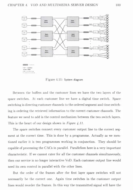
4.5 Digital Im p lem en tatio n ... 96
4.5.1 Pricing memory and controller-sw itches... 102
4.5.2 The controller f u n c t i o n s ... 103
C O N TEN TS 10
4.6 Summary ... 105
5 R eview of bibliography on VoD system s 106 5.1 In tro d u c tio n ...106
5.2 Centralised and distributed m a n a g e m e n t... 107
5.2.1 Problems of D is trib u tio n ... 108
5.2.2 Optimisation and Automation of distributed control . . . 110
5.2.3 Distributed method o p tim is a tio n ... I l l 5.3 Review of b ib lio g ra p h y ...115
5.3.1 A store-and-forward architecture for video-on-demand ser vice [1] ... 115
5.3.2 Content Hosting in Full Service Broadband Delivery in frastructures: Efficiencies, Architecture and Policy [2] . 118 5.3.3 A cost comparison of Distributed and Centralised Ap proaches to Video-on-Demand [3 ]... 123
5.3.4 An Architecture for interactive applications [ 4 ] ... 125
5.3.5 Summary of reviewed m e th o d s...127
5.4 S u m m a r y ... 128
6 M anagement Scheme for distributed IMS 130 6.1 In tro d u c tio n ... 130
6.2 Distributed VoD and management system ...130
6.3 Management s y s t e m ... 133
6.3.1 P r in c ip le s ... 134
6.4 S u m m a r y ... 137
C O NTEN TS 11
7.1 In tro d u c tio n ... 138
7.2 Algorithm D e s c r ip tio n ... 139
7.2.1 Simulation framework ... 139
7.2.2 Network s e a r c h ...142
7.2.3 R elo ca tio n ... 143
7.2.4 Movie rem oval... 143
7.2.5 Forced movie term ination ... 144
7.3 P s e u d o c o d e ... 144
7.4 QoS f a c t o r ... 147
7.4.1 Comparison criterion-Cost f u n c tio n ...148
7.5 S u m m a r y ... 151
8 Perform ance o f th e proposed algorithm 152 8.1 In tro d u c tio n ... 152
8.2 S im u la tio n ... 153
8.2.1 Probability g e n e ra to r... 153
8.2.2 Simulation p a r a m e te r s ...154
8.3 R e s u lts... 155
8.4 C o n c lu sio n s... 194
8.5 S u m m a r y ... 194
9 Comparison to non-distributed system s 196 9.1 In tro d u c tio n ... 196
9.2 Distributed servers without control algorithm ...196
9.3 Centralised s y s t e m ... 197
9.4 R e s u lts... 198
9.5 C onclusion... 210
CO N T EN T S 12
10 Conclusions 212
10.1 In tro d u c tio n ... 212
10.2 Contributions of this th e s is ...213
10.3 Suggestions for further w o r k ...214
List o f F igures
2.1 26
2.2 29
2.3 32
2.4 34
2.5 36
2.6 36
2.7 42
2.8 46
3.1 74
4.1 82
4.2 83
4.3 87
4.4 88
4.5 89
4.6 91
4.7 92
4.8 95
4.9 97
4.10 ... 99
4.11 ... 100
5.1 113
5.2 114
L IS T OF FIGURES 14
5.3 116
5.4 118
5.5 119
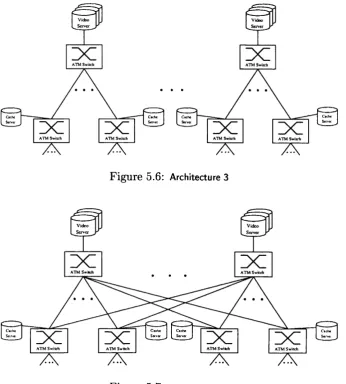
5.6 120
5.7 120
5.8 123
5.9 125
5.1 0 ... 126
6.1 131 6.2 134 6.3 135 7.1 140 7.2 145 8.1 154 8.2 157 8.3 158 8.4 159 8.5 159 8.6 160 8.7 161 8.8 162 8.9 162 8.1 0 ... 163
8.11 ... 163
8.1 2 ... 164
8.1 3 ... 165
8.1 4 ... 165
L IS T OF FIGURES 15
8.1 6 ... 167
8.1 7 ... 168
L IS T OF FIGURES 16
8 . 4 6 ...194
9.1 199 9.2 200 9.3 201 9.4 201 9.5 202 9.6 203 9.7 204 9.8 205 9.9 205 9.1 0 ... 206
9.11 ... 207
9.1 2 ... 208
9.1 3 ...209
9.1 4 ... 209
List o f Tables
2.1 35
2.2 49
5.1 124
C hapter 1
In trod u ction
M ultimedia service design and implementation has only recently been a topic
of research as new technologies made their realisation feasible. VoD (Video-
on-Demand) is only one of a range of interactive services; others include NoD
(News-on-Demand), audio on demand, interactive shopping etc.
By definition VoD is the on demand delivery of films to the end user, with
interactive functionality provided.
The main characteristics of the VoD service are:
1. support of multiple non-synchronous connections to one film
2. support of interactive functions on the delivered material
3. independent viewing for each user
These characteristics apply to VoD, and to interactive multimedia services
in general, and they impose new requirements on the service provider in order
to realise them.
This thesis presents a generic service design for VoD th at will make it avail
able to a large customer base. We have chosen a distributed VoD server model.
The distributed model was chosen because it can oflfer scalability to cover future
service demand trends, disperse m aterial where is needed in the user network
and can tolerate and adapt to partial server failure.
T
^ 4a \
C H AP T E R 1. INTRO D U CTIO N 19
We identify the most im portant components of the service as being the
following:
• the VoD server and
• the service management system
We propose a generic design for a scalable, interactive VoD server and a simple
service management system.
The most im portant VoD server design requirements are:
• support of multiple connections to one film
• support of non-synchronised user connections to a number of films
• provision of real-time interactive actions such as pause and forward and
backward scanning at any speed, or at random.
• scalable design to accommodate growing user demand
For the servers to operate successfully, a service control protocol is needed.
The control protocol will manage movie and connection placement. The most
im portant system resources have been identified as server space and network
bandwidth. The control system is constructed in order to manage these two
resources in the best possible way, while offering high film availability to the
end user. We propose a simple management system based on the incoming
user requests. Movies are classified according to these requests and treated
accordingly. Furthermore, two system procedures are performed to improve
film availability.
1.1
O rganisation o f th esis
The thesis is organised in ten chapters. The first is this introductory chapter.
In the second chapter we provide a review of the enabling technologies for
CH A P T E R 1. IN TRO D U CTIO N 20
to the user of video m aterial, such as movies, documentaries, video clips, etc.
The provision of analogue video interactively to the end user is not profitable
due to the large bandwidth required for the provision of one analogue channel
(8MHz). Progress though on digital compressed video has led to the transm is
sion of acceptable image quality at a rate as low as 1.5M bit/s. This bit rate
though far exceeds the rate th a t can be supported by twisted copper pair tele
phony connections th at reach almost each home in this country and the EU.
The appearance and progress in xDSL (Digital Subscriber Line) technology has
brought the realisation of multimedia technology closer. xDSL technology is
the easy alternative to a complete last loop upgrade to fibre, and is preferred
by network providers because of its reduced installation cost. Additionally,
CaTV coax cable networks provide extra bandwidth for this purpose. SDH and
ATM and the upgrade of backbone networks to T b its/s d a ta rates provide the
framework for a large scale implementation of distributed services. The next IP
version, the IPng will provide extra functionality and support for time sensitive
applications, will bring even closer the wide scale im plementation of multimedia
services.
In the third chapter we present an overview on the most im portant VoD trials
performed by telecommunications operators, and introduce the most im portant
VoD service elements.
In the forth chapter we compare the VoD service designs presented in the
literature. These designs vary in concept and degree of interactive service pro
vision. They either provide evidence to illustrate the benefits of a distributed
solution compared to a centralised, or study a distributed VoD service network.
In the fifth chapter we present our design for a VoD server, supporting mass
and interactive user connections. As the server is one of the most im portant
elements of the VoD service, its performance will be reflected in overall service
performance. Our server is based on a two tier architecture. On the first tier,
staggered multicast at very short time intervals are used to provide the movie
C H A P T E R 1. INTRO D U CTIO N 21
control for the interactive service is provided.
In the sixth chapter we present our design for the VoD server management
system. As our VoD service design is a distributed one, the management system
will be responsible for service operation. Our system is based on heuristics, it
uses as little network information as possible and makes decisions based on the
current popularity of movies received from the network. The movies are divided
into three groups depending on popularity. The distance to the remote connec
tions allowed for these movies is based on their popularity group. The servers
cooperate in order to start a new movie and a search procedure is developed.
Further, a relocation process is developed, which relocates less popular movies
in order to make space available for more popular ones.
In the seventh chapter we present the simulation network we used in our
study. The servers are placed in a regular square grid network, the movie
library holds 100 movies and the server capacity is varied from 1 to 15 movies
simultaneously available. The management scheme connects the users to their
local server firstly, then if this is not possible an attem pt is made to find the
movie in a small cluster of neighbouring servers. If this fails the movie is started
locally or remotely depending on network conditions. Relocation is allowed
when connection is not possible and if relocation fails, a movie is discontinued ; i jC
■
I
11
only when certain conditions apply in order to m aintain QoS.
In the eighth chapter we present the results we obtained using our simulation
framework and applying different system and control parameters. A changing
probability profile is used to simulate change in demand during the course of a
day. Finally, two different search ranges are studied for the relocation process,
one where relocation is allowed to the whole of the network and one where
relocation is limited to half the network.
In the ninth chapter we compare our results of the distributed system to a
centralised system and to a system of independent servers. Our system performs
better in all cases, and provides the best quality of service.
CH A P T E R 1. IN TRO D U CTIO N 22
1.2
Sum m ary o f m ain contributions
The study presented in this thesis offers the design guidelines for the implemen
tation of a real VoD service. The m ajor contributions into four areas and can
be summarised as follows:
• Design of an interactive, scalable multimedia server, where the design in
troduced is based on existing off the shelf components with added control.
• Design of a low complexity service control protocol which can be easily
implemented.
• Service system requirements and network dimensioning in order to suc
cessfully support a VoD service.
• Least system settings required to satisfy system cost and QoS require
ments.
The work carried out for this thesis has led to the following publications:
1. K. Papanikolaou and M. Wilby: “Design outline for Video-on-Demand
server” . Fifth lE E Conference on Telecommunications, Brighton UK 1995.
2. K. Papanikolaou and M. Wilby: “Administration System for Home Ser
vices offered by M etropolitan Area Networks” , Eighth IE E E Workshop on
Local and Metropolitan Area Networks, Berlin, Germany 1996.
3. K. Papanikolaou and M. Wilby: “Network and Control requirements for
a distributed VoD Service” , IE E E Symposium on planning and design of
broadband networks, Montebello, Quebec, Canada, Oct. 96.
4. K. Papanikolaou and M. Wilby: “Architecture for a Networked VoD Ser
vice in a Multimedia Environment” , IEE E R O C & C /IT S ’96, Mexico 1996.
5. K. Papanikolaou and M. Wilby: “Control Protocol for Distributed Multi-
media System Modelled on VoD” , IEEE Singapore International Confer
C H A P T E R 1. IN T R O D U C T IO N 23
6. K. Papanikolaou and M. Wilby: “Management Scheme for VoD Server
Network ” , Network and Optical Communications 1996: A T M Networks
and L A N ’s, N O C ’96, Heidelberg 1996.
1.3
Sum m ary
This chapter provides an introduction to the subject of the thesis; the design
of a distributed VoD service. The m ain characteristics of both server and m an
agement system design are presented. The organisation of the thesis follows.
Finally, the main contributions of the thesis are summarised along with a listing
of the published papers based on the research work presented in this thesis. In
the next chapter we present an overview of the multimedia enabling technolo
C hapter 2
S u p porting T echnologies
The implementation of interactive multimedia services in the residential market
has been brought closer due to a number of technological advancements th at
appeared at the beginning of the last decade [5]. These achievements cover a
broad spectrum of fields, including image compression and transmission, pro
cessing power, memory and backbone networks. Highly efficient digitised video
compression can considerably reduce the bandw idth requirements for accept
able video quality. Digital transmission and signal processing techniques can be
used to increase the capacity of the standard twisted pair wire. Advancements
in processing power and memory have also made possible the efficient handling
of moving image data. Finally, the introduction of ATM based backbone net
works, in conjunction with the other advancements in transport protocols such
as IPv6, further facilitate the introduction of new services.
2.1
Introduction
In this chapter we present the most im portant of the VoD supporting technolo
gies, which will play a significant role in the telecommunications and service net
works of the future. First we present the image compression standards. These
are the MPEG and JPE G digital image compression standards for moving and
still images respectively. MPEG compresses the analogue moving picture signal
C H A P T E R 2. SUPPORTING TECHNOLOGIES 25
from 150M bit/s down to 1.5-40Mbit/s depending on quality. This has made
video delivery to the home much more feasible than ever before.
Next we present an overview of the Access Networks of the future. Fibre is
the only future proof medium, but the civil engineering costs make the network
operators rather reluctant to implement it at this time. Copper pair is not yet
obsolete thanks to ADSL, an xDSL digital transmission technology which can
m ultiply copper pair bandwidth so th at 2 to 3 M bit/s are feasible for the home
user. Coax networks mainly installed by CaTV operators can be used especially
when upgraded for two-way communications. Wireless transmission can provide
access with minimum costs of installation and maintenance to densely populated
areas.
In the section on network technology we present ATM and IPv6 as two trans
port protocols th at could carry the interactive multimedia services. Although
ISDN as a digital services network has been proposed for quite some time, its
im plementation has taken telecommunications companies too long. Installation
and usage costs are still considered high in most European countries, the UK
included.
2.2
C om pression Standards
Image compression has brought nearer the date of multimedia service imple
m entation. Using image compression, the existing infrastructure can be used to
deliver video to the residential user. The quality of the delivered image will be
comparable to th at now broadcast or delivered on cable. Additionally, image
quality can be tailored to specific network capabilities.
2.2.1 JP E G
JP E G is a standardised image compression mechanism. JPE G stands for Joint
Photographic Experts Group, the original name of the committee th a t devel
C H A P T E R 2. SUPPORTING TECHNOLOGIES 26
grey-scale digital images of natural (real-world) scenes. It is not very efficient
in handling black and white (one bit/pixel) images, nor does it handle motion
picture compression. Nevertheless, it could be used for still image compression
when this is needed, for example in menus etc. JPE G uses the same compression
techniques as MPEG apart from those especially used for temporal redundancy.
Again the low frequency information is preserved as much as possible whereas
the high frequency details are sacrificed for compression.
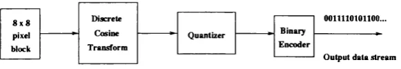
BLOCK DIAGRAM OF JP E G COMPRESSION
OOllllOIOllOO...
O utput data stream Binary
Encoder 8 x 8
pixel block
Q uantizer Cosine
Transform Discrete
Figure 2 .1 : JPEG compression process
Figure 2.1 describes the JPE G process. JPE G divides the image into 8 x 8
pixel blocks, and then calculates the discrete cosine transform (DCT) of each
block. A quantizer rounds off the DCT coefficients according to the quantization
m atrix. This step produces the “lossy” nature of JPE G , but allows for large
compression ratios. JP E G ’s compression technique uses a variable length code
on these coefficients. For decompression, JPE G recovers the quantized DCT
coefficients from the compressed d ata stream, takes the inverse transforms and
displays the image.
JPE G is lossy, in th a t the reconstructed image after decompression is not
identical to the originally coded image. The algorithm achieves much of its
compression by exploiting a known lim itation of the human eye-it is less sensi
tive to high frequency details. Small colour details are not perceived as well as
small details of light-aud-dark. Thus, JPE G is intended for compressing images
th a t are to be looked at by humans. When using JPE G compressed images
in digital image processing we must be aware th at they are different (detail is
lost) to the original picture, due to the encoding process. A useful property
CH A P T E R 2. SUPPORTING TECHNOLOGIES 27
parameters. This allows the image maker to trade off file size against output
image quality. Extremely small files can be made if high image quality is not
required; this is useful for indexing image archives, making thumbnail views
of icons etc. Conversely, high image quality can be achieved by relaxing the
compression ratio.
Although it handles colour files well, it is limited in handling black-and-
white and files with sharp edges (the compression ratio is rather small). The
processing especially the compression cost, even on up-to-date computers, is
also high. Further information is available from [6].
2.2.2
M PE G
Moving Pictures Expert Group (MPEG) is the name of the standard which has
been produced by the ISO committee on digital colour video and audio compres
sion. MPEG was initially developed for storage purposes. Provisions were there
fore made in the algorithm to enable random access and fast-forward/ reverse
searches, when decoding from any digital storage media. However, the cod
ing standard is fiexible enough to be suitable for a much wider range of video
applications. Appropriate modifications may be introduced in order to reduce
the end-to-end delay due to the transmission process and further adapt the
standard to network applications [7, 8].
MPEG is a highly efficient algorithm and can produce up to a 200:1 compres
sion ratio for fairly unchanging video sequences. The compression rate depends
on the video being coded, fast changing scenes dictate a lower compression ra
tio. In MPEG both spatial and temporal information redundancy is removed.
The MPEG standard has three parts: the video encoding, the audio encoding,
and the systems part. In the video encoding part, spatial and temporal redun
dancies are removed; only the frames without any such redundancy are coded to
full extent. Audio is also coded to reduce bandwidth requirements. The system
part includes synchronisation information of the audio and video streams which
C H APTE R 2. SUPPORTING TECHNOLOGIES 28
Two features of the algorithm are the most im portant from the video view
point. These are the coding layers and the coding modes. The video frame
is hierarchically segmented into coding layers. By segmenting the frame the
particular features of the algorithm can be used to its full extent to improve
compression efficiency. Highly detailed areas are coded using more data, thus
keeping image quality at acceptable levels, whereas simpler areas can be coded
more efficiently.
The coding modes are determined by the information in each frame. Frames
which designate a scene change are unique and therefore coded to a full extent
without any reference to previous or next frames. The frames between two
scene changes are coded according to their resemblance. Some frames are only
dependent on previous frames, but others are dependent on previous as well as
following frames. Accordingly, the compressed frames may not be broadcast in
absolute time sequence.
L a y ers a n d m o d e s
The video sequence to be MPEG compressed is usually divided into four layers,
each with different use and functionality. The layers are arranged as follows.
• B lo ck A block is the smallest coding unit in the MPEG algorithm. It is
made up of 8 x 8 pixels and can be of three types: Luminance (Y), red
chrominance (Cr) and blue chrominance (Cb). The block is the basic unit
for intraframe DCT (Digital Cosine Transform) coded blocks.
• M a c ro b lo c k - A macroblock (MB) is the basic coding unit in the MPEG
algorithm. A macroblock is a 16 x 16 pixel segment of Luminance com
ponents and the corresponding 8 x 8 pixel section of the two chrominance
components. Because the human eye is not very sensitive to the chroma
region changes, as compared to the luminance region, the chroma m atri
ces are usually decimated or reduced in size by a factor of two in both
CHAPTER. 2. SUPPORTING TECHNOLOGIES 29
forth the number of chrominance pixels to process as there are luminance
pixels. This format, referred as 4:2:0 format, is employed in MPEG-1.
MPEG-2 additionally allows for either no decimation or only horizontal
decimation of the chroma component. These two formats are referred to
as 4:4:4 and 4:2:2 formats respectively. Pictures can be categorised into
three main types based on their compassion schemes. Since each verti
cal component has one-half the vertical and horizontal resolution of the
Luminance component, a macroblock consists of 4 Y, 1 Cr and 1 Gb block.
• S lice- A slice is a horizontal strip of macroblocks within a frame. Coding
operations on blocks and macroblocks can only be performed when all
pixels for a slice are available. A slice is an autonomous unit since coding
for a slice is done independently from its neighbours.
Slices are important in the handling of errors. If the bitstream contains
an error, the decoder can skip to the start of the next slice. Having more
slices in the bitstream allows better error concealment, but uses bits that
could otherwise be used to improve picture quality.
• P ic tu r e A picture in MPEG terminology is the basic unit of display and
corresponds to a single frame in a video sequence.
Figure shows the MPEG layer hierarchy, from blocks to the frame sequence.
|--- Video Sequence — -
-Group of Pictures ---- ,
P ic tu r e /
Block Slice M acroblock
8
p ix e ls
K *p ix e ls
C H APTE R 2. SUPPORTING TECHNOLOGIES 30
A picture consists of three rectangular matrices representing luminance (Y)
and two chrominance (Cb and Cr) values. The Y m atrix has an even number
of rows and columns. The Cb and Cr matrices are one-half the size of the Y
m atrix in each direction (horizontal and vertical).
The spatial dimensions of the frame are variable and determined by the
application requirements. A frame made up of 485 x 720 pixels corresponds to
the NTSC standard or 576 x 720 to PAL, a similar resolution in M PEG would
be sufficient to replace the analogue standards. VHS requires an even lower
resolution of 352 x 240.
In the MPEG coding scheme, a choice of several coding modes is available
at the frame and macroblock level. For encoded frames three modes can be
utilised:
• I ( in tr a ) frames are coded as still images.
• P (fo rw a rd p r e d ic te d ) frames can be predicted from the most recent I
or P frame.
• B (b i-d ire c tio n a lly p r e d ic te d ) frames are interpolations between I and
P frames.
Each frame is encoded according to its properties. Typically, the I frames
are sent once every 10 or 12 frames. Reconstructing a B frame for display
requires the preceding and following I an d /o r P frames. The coded frames are
sent out of time-order, to compensate for the B-pictures which need the next
picture present for reconstruction. In a network environment, this would require
bigger buffers, so th at all the required frames could be stored on a buffer before
reconstruction. The system could be prone to delays and consequently loss
of image quality if no guarantees are given on transfer tim e by the transport
protocol.
In more detail, intra pictures, or I-pictures, are coded independently, us
C H APTE R 2. SUPPORTING TECHNOLOGIES 31
random access points into the compressed video data. The whole I frame under
goes 8 x 8 block-based Discrete Cosine Transform (DCT) for the luminance and
chrominance components, without referring to other frames. The DCT coeffi
cients are then quantized. The DCT coefficients of individual blocks are coded
diflFerently within a slice. I-pictures typically use about two bits per coded pixel.
Predicted pictures, are coded with respect to the nearest previous I or P
picture. This technique is called forward prediction. As for I pictures, P
pictures serve as a prediction reference for B pictures and future P pictures.
However, P pictures use motion compensation (MC) which is discussed in sec
tion 2.2.2 to provide more compression than is possible with I pictures. For
interframe-coded frames (P), temporal redundancy is first reduced by causal
MB (Macro-Block)-based motion compensation, a temporal redundancy elim
inating technique, with respect to the preceding I or P frames stored in the
Frame Storage. If the motion estim ation (ME) error is less than a threshold
(i.e. there is enough redundancy the interframe-coding is worthwhile), then the
motion vector (MV) will be differentially coded using variable length coding
(VLC), while the ME error will undergo DCT, coarse quantization, and then
VLC. Otherwise, th at MB will undergo intraframe-coding. Differential coding
is used because it reduces the total bit requirement by transm itting the differ
ence of the motion vectors of consecutive frames. The compression efficiency
and the quality of the reconstructed video depend on the accuracy of the motion
estimation. Unlike I pictures, P pictures can propagate coding errors because
P pictures are predicted from previous reference (I or P) pictures.
Bidirectional pictures, or B pictures, are pictures th a t use both a past and
future picture as a reference for motion compensation. This technique is called
bidirectional prediction. Figure 2.3 illustrates the relation of the three picture
types. Prediction is non-causal since both past and future frames are used.
B pictures provide the most compression and do not propagate errors because
they are never used as a reference, but display already propagated errors. Bidi
CHAPTER 2. SUPPORTING TECHNOLOGIES 32
Forw ard P red iction
k
1
B id irectio n a l P red ictio n
Figure 2 .3 : MPEG standard coding example
Bidirectioiially predicted (B) frames are coded in a way similar to coding P
frames; however, the motion compensation is bidirectional with respect to both
preceding and following P (or I) frames [9].
An MPEG coded sequence is characterised by three parameters: q, N and
M. The quantization factor q controls the degree of fitness of quantization.
— 1 is the number of frames coded between successive I frames, while M — I
is the number of B frames coded between successive P frames. A group of
frames (GOF) with N = 10, M = 3 is as follows:
IBBPBBPBBP
D ata in an MPEG coded video stream are of unequal importance. When
d ata in I or P frames are lost during transmission, the frame contents in the
Frame Storage at the coder and decoder become different. Even if no further
d ata is lost, for the following P or B frames, the ME at the coder and decoder
will refer to different frame contents at the “baseline” of estimation. Gonse-
quently errors due to d ata loss of one I or P frame will propagate along the
following P and B frames, and this is often referred to as error propagation.
The accumulated errors can be cleared by sending an I frame.
M P E G C o d in g
C H APTE R 2. SUPPORTING TECHNOLOGIES 33
• Discrete cosine transform (DCT)
• Quantization
• Run-length encoding
Both image blocks and prediction-error blocks have high spatial redundancy.
To reduce this redundancy, the MPEG algorithm transforms 8 x 8 blocks of
pixels or 8 X 8 blocks of error terms from the spatial domain to the frequency
domain with the Discrete Cosine Transform (DCT). DCT is a time to frequency
transform, which exploits the spatial correlation of the pixels by converting them
to a set of independent coefficients. The low frequency coefficients contain more
energy than the high frequency ones. This process allows the high energy, low
frequency coefficients to be coded with greater number of bits, while using
fewer or zero bits for the high frequency, low energy coefficients. Equation
2.1 represents the two-dimensional DCT transform operation th a t should be
applied on a 8 x 8 pixel block. This is done separately for the luminance and
chrominance components. The two-dimensional DCT can be separated in a
number of sequential one-dimensional DCTs, for the 8 x 8 case, eight 8 x 1
DCTs followed by eight 1 x 8 DCTs. DCT is quite a complex computation and
a number of algorithms have been developed to reduce its complexity [10], for
example:
1 7 7
F{u, u) = - C{u)C{v) ^ ^ cos(7t(22; H- l)u/16)cos(7r(2?/ -t- l)u /1 6 ) (2.1)
x = 0 y = 0
where.
Next, the algorithm quantizes the frequency coefficients. Quantization is the
process of approximating each frequency coefficient as one of a limited number
of allowed values. The encoder chooses a quantization m atrix th a t determines
C H A P T E R 2. SUPPORTING TECHNOLOGIES 34
of quantization error is lower for high spatial frequencies, so high frequencies
are typically quantized more coarsely (i.e., with fewer allowed values) than low
frequencies.
Discrete Cosine Transform
Large coefficients
Quantization, Zigzag Scan, Run-length Coding
y
I
z
z
z
z
zz
zz
z:
Image Samples Frequency Small
Coefficients
8x8 P ixel B lock 8x8 D C T B lock
Figure 2 .4 : Transform Coding Operations
Run-Amplitude Symbols
Some blocks of pixels need to be coded more accurately than others. For ex
ample, blocks with smooth intensity gradients need accurate coding to avoid vis
ible block boundaries. To deal with this inequality between blocks, the MPEG
algorithm allows the amount of quantization to be modified for each macroblock
of pixels. This mechanism can also be used to provide smooth adaptation to a
particular bit rate.
The transform exploits the spatial correlation of the pixels by converting
them to a set of independent coefficients. The low frequency coefficients con
tain more energy than the high frequency ones. These coefficients are quantized
employing a quantization m atrix. This process allows the high energy, low fre
quency coefficients to be coded with a greater number of bits, while using fewer
or zero bits for the high frequency, low energy coefficients. The high frequency
coefficients can afford to be dropped because the eye lacks the ability to detect
high frequency changes. Retaining only a subset of the coefficients reduces the
total number of param eters needed for representation by a substantial amount.
C H APTE R 2. SUPPORTING TECHNOLOGIES 35
MPEG TOOLS RE D U N D AN C Y EX PLO ITED
DCT Spatial
MC Prediction/Interpolation Temporal
Run Length/ Huffman Coding
Differential Coding Temporal
T a b le 2 .1 : MPEG Tools
However, since the human visual sensitivity to the luminance and chroma varies,
the quantization matrices for the two differ. The quantization process also helps
in rate control, i.e. allowing the encoder to output bitstream s at a specified bi-
trate. The DCT are coded employing a combination of two lossless coding
schemes-Run Length and Huffman. The coefficients are scanned in a zigzag
pattern to create 1-D sequence (see Figure 2.4)- MPEG-2 can additionally
provide a different scan pattern as an alternative. The resulting 1-D sequence
usually contains a large number of zeros due to the lowpass nature of the DCT
spectrum and the quantization process. Each non-zero coefficient is associated
with a pair of pointers. First, its position in the block which is indicated by
the number of zeros between itself and the previous non-zero coefficient. Sec
ond, its coefficient value. Based on these two pointers, it is allotted a variable
length code from a lookup table. This is done in a manner so th a t a highly
probable combination gets a code with fewer bits, while the unlikely ones get
longer codes. Adopting this lossless coding technique the total number of bits
is kept down. However, since spatial redundancy is limited, the I pictures pro
vide only moderate compression. These pictures provide im portant hooks for
random access into the digital bitstream for editing and viewing purposes.
MPEG is a clever combination of a number of diverse tools th at exploit
temporal and spatial redundancy. It is efficient and can offer a variety of quali
ties according to the application. Advancements in coding and processing have
made the realisation of real-time video services possible. Table 2.1 summarises
C H APTE R 2. SUPPORTING TECHNOLOGIES 36
V ideo Stream Com position
The MPEG algorithm allows the encoder to choose the frequency and location of
I pictures. This choice is based on the application’s need for random accessibility
and the location of scene cuts in the video sequence. In applications where
random access is im portant, I pictures are typically used two times a second.
2 B -p iclu r« between reference (P)pictures
one 1-picture every 15th fttime (1/2 secondât 30Hz)
Picture Type. I B B P B B P B B P B B P B B I B B P B B P B B P B B P B B
Display Older: 1 2 3 4 5 6 7 8 9 10 11 12 13 14 15 16 17 18 19 20 21 22 23 24 25 26 27 28 29 30
Figure 2 .5 : Typical display order of picture types
The encoder also chooses the number of B-pictures between any pair of
reference (I or P) pictures. This choice is based on factors such as the amount
of memory in the encoder and the characteristics of the m aterial being coded.
For example, a large class of scenes have two bidirectional pictures separating
successive reference pictures. A typical arrangement of I, P, and B pictures is
shown in Figure 2.5 in the order in which they are displayed.
Display Order
I
B
B
P
B
B
P
1 2 3 4 5 6 7
Video Stream Order
I
P
B
B
P
B
B
4 2 3 7 5
Figure 2.6: Typical display order of picture frames
The MPEG encoder reorders pictures in the video stream to present the
pictures to the decoder in the most efficient sequence. In particular, the ref
C H A P T E R 2. SUPPORTING TECHNOLOGIES 37
B pictures. Figure 2.6 demonstrates this ordering for the first section of the
example shown above.
M otion Com pensation
Motion compensation is a technique for enhancing the compression of P and B
pictures by eliminating tem poral redundancy. Motion compensation typically
improves compression by about a factor of three compared to intra-picture cod
ing. Motion compensation algorithms work at the macroblock level.
When a macroblock is compressed by motion compensation, the compressed
file contains the following information:
• The spatial vector between the reference macroblock(s) and the mac
roblock being coded (motion vectors)
• The content differences between the reference macroblock (s) and the mac
roblock being coded (error terms)
Not all information in a picture can be predicted from a previous picture.
Consider a scene in which a door opens: The visual details of the room behind
the door cannot be predicted from a previous frame in which the door was
closed. When a case such as this arises-i.e., a macroblock in a P picture cannot
be efficiently represented by motion com pensation-it is coded in the same way
as a macroblock in an I picture using transform coding techniques.
The difference between B and P picture motion compensation is th a t mac
roblocks in a P picture use the previous reference (I or P picture) only, while
macroblocks in a B picture are coded using any combination of a previous or
future reference picture.
Four codings are therefore possible for each macroblock in a B picture:
• Intra coding: no motion compensation
• Forward prediction: the previous reference picture is used as a reference
C H A P T E R 2. SUPPORTING TECHNOLOGIES 38
• Bidirectional prediction: two reference pictures are used, the previous
reference picture and the next reference picture
Backward prediction can be used to predict uncovered areas th at do not appear
in previous pictures.
A udio Stream D ata Hierarchy
The M PEG standard defines a hierarchy of d a ta structures th at accept, decode
and produce digital audio output. The MPEG audio stream, like the MPEG
video stream, consists of a series of packets. Each audio packet contains an
audio packet header and one or more audio frames.
Each audio packet header contains the following information:
• Packet start code - Identifies the packet as being an audio packet.
• Packet length - Indicates the number of bytes in the audio packet.
An audio frame contains the following information:
• Audio frame header - Contains synchronisation, ID, bit rate, and sampling
frequency information
• Error-checking code - Contains error-checking information
• Audio data - Contains information used to reconstruct the sampled audio
data.
• Ancillary data - Contains user-defined data.
A udio and video m ixing
When audio is digitally stored, like on a conventional audio CD, a m ethod called
Pulse Code Modulation (PCM), is usually used. Despite the fact th a t audio
stored in this manner takes up a lot less space than regular image information, it
still is not sufficiently compact compared to MPEG-Video. For this reason, the
C H APTE R 2. SUPPORTING TECHNOLOGIES 39
to the compressed image information. This audio compression technique used is
MPEG-Audio compression according to ISO 11172-2. This method makes use
of Huffman-encoding and the psycho-acoustic model. The Huffman-encoding
exploits repetitive patterns and redundancy, while the psycho-acoustic model
exploits the shortcomings of the human brain, which is incapable of simul
taneously “hearing” different sound frequencies th a t are close together in the
spectrum. The brain will only (or mainly) detect the loudest or most promi
nent frequency, and ignore almost all frequencies close around this prominent
frequency th at aren’t loud enough. For this reason, it is not necessary to store
all sound information, but only the “remarkable” parts. This m ethod does
not effect stereo or Dolby surround pro-logic information. The result is very
compactly stored sound information, with near CD-perceived audio quality.
MPEG-2 audio is a compatible extension to MPEG-1 audio encoding, which
enables the transmission of mono, stereo, or multichannel audio in a single
bitstream . It can operate at a wide range of bit rates (8 k b it/s up to more than
1 M bit/s) and supports sampling rates of 16, 22.05, 24, 32, 44.1 and 48 kHz.
For stereo, a typical application would operate at an average bit rate of 128-256
kbit/s. A multichannel movie soundtrack requires an average bit rate of 320-640
k b it/s, depending on the number of channels and the complexity of the audio to
be encoded. MPEG-2 defines an extension for five full bandwidth channels plus
a low frequency enhancement (LEE) channel, termed 5.1 multichannel. W ith an
additional compatible extension, seven channels are possible (7.1 multichannel).
In devising an encoding method, the basis had to be the human ear. Al
though not a perfect device for acoustic reception, advantage was taken of one of
its characteristics: a non-linear and adaptive threshold of hearing. The thresh
old of hearing is the level below which a sound is not heard. It varies with
frequency and, of course, between individuals. Most people’s hearing is most
sensitive between 2 and 5 kHz. W hether a person hears a sound or not depends
on the frequency of the sound and whether the am plitude is above or below
C H APTE R 2. SUPPORTING TECHNOLOGIES 40
The threshold of hearing is adaptive, and is constantly changed by the
sounds heard. For example, an ordinary conversation in a room is perfectly
audible under normal conditions. However, the same conversation in the vicin
ity of a loud noise, such as an aircraft passing low overhead, is impossible to
hear due to the distortions introduced to the hearing thresholds of the individ
uals concerned. When the aircraft has gone the hearing thresholds return to
normal. Sounds th at are inaudible due to dynamic adaptation of the hearing
threshold are said to be “masked” .
This effect is universal but is of particular relevance in music. An orchestra
instrum ent playing fortissimo will, to a greater or lesser extent, make the sound
of some other instruments inaudible to the human ear. When the music is
recorded, however, all the frequencies go on the medium because the response
of the recording device is flat, i.e. it is not dynamically adaptive. When the
recording is played the masked instrum ents will not be audible to the listener. A
linear recording, as used on CD, is inefficient in this respect. To make the best
use of a recording medium the parts of the medium th at contain inaudible data
can better be used to store audible data. In this way a fixed capacity recording
medium can contain a considerably increased amount of audio without any
loss of quality, as is perceived by the human ear. Also, the demands on a
transmission link carrying the information are reduced.
The MPEG-2 standard was designed with compatibility being a m ajor con
sideration. W ith the ever growing number of applications of MPEG-1 audio,
especially in the entertainment, satellite broadcasting and multi-media fields,
this compatibility will provide the consumer a cross-platform format to enjoy
high quality audio reproduction. The core of the MPEG-2 bitstream is an
MPEG-1 bitstream which enables fully compatible decoding by an MPEG-1
audio decoder. In addition, the need to transfer two separate bit stream s (one
for stereo and another one for the multichannel audio program) is avoided. In
other words, a future upgrade of e.g. DSS (Digital Subscriber System) with
C H APTE R 2. SUPPORTING TECHNOLOGIES 41
ones will reproduce stereo, the new ones high quality multichannel sound.
An MPEG-1 decoder will be supplied in the MPEG-1 p art of the bitstream
with an appropriate (stereo) “downmix” of all channels in the multichannel
frame. The left and right channel of the stereo signal contain components of
all the channels, according to the equations in the compatibility m atrix. The
MPEG-1 (stereo) decoder decodes the stereo part of the MPEG-2 frame, and
ignores the multichannel extensions. MPEG-2 defines four m atrix sets, one of
which is selected in the decoder from information in the MC (multichannel)
frame header.
Synchronisation
The MPEG standard provides a timing mechanism, using time stam ps th a t
ensures synchronisation of audio and video. This method allows the provision of
flexibility in decoder design, packet length, audio sample rates, coded data rates
and network performance. The decoder can use the time stam p information to
display frames accordingly, frames with expired time stam ps can be discarded,
whereas frames th at have arrived early can be saved in a buffer. The standard
includes two parameters: the system clock reference (SCR) and the presentation
tim estam p (PTS).
The MPEG-specified “system clock” runs at 90 kHz. System clock reference
and presentation tim estam p values are coded in MPEG bitstream s using 33 bits,
which can represent ciny clock cycle in a 24-hour period.
For example C-Cube Microsystems uses a System Clock Reference (SCR)
called CL480 to help synchronise picture and sound during reproduction.
An SCR is a snapshot of the encoder system clock which is placed into the
system layer of the bitstream , as shown in Figure 2.7. During decoding, these
C H A P T E R 2. SUPPORTING TECHNOLOGIES 42
MPEG system stream
with SCRs and PTSs
SCRs
CL480
Video Decoder
Encoder System
Clock
Audio Decoder MPEG
Encoder
System D ecoder
Figure 2 .7 : SCR Flow in MPEG System
P r e s e n ta tio n T im e s ta m p s
Presentation timestamps (PTS) are samples of the encoder system clock th a t
are associated with video or audio presentation units. A presentation unit is a
decoded video picture or a decoded audio time sequence. The PTS represents
the time at which the video picture is to be displayed or the starting playback
time for the audio time sequence.
The decoder either skips or repeats picture displays to ensure th a t the PTS
is within one picture’s worth of 90 kHz clock ticks of the SCR when a picture
is displayed. If the PTS is earlier (has a smaller value) than the current SCR,
the decoder discards the picture. If the PTS is later (has a larger value) than
the current SCR, the decoder repeats the display of the picture.
M P E G v ersio n s
There are four MPEG (two of these still developing) standards varying in bit-
rate and in the quality of the moving picture offered. MPEG-1 was originally
designed for delivery of video to consumer devices when single speed CD-ROM
d ata rates were 1.5M bit/s, supporting super VHS quality video.
MPEG-2 is a standard for digital television and offers b etter resolution
CH APTE R 2, SUPPORTING TECHNOLOGIES 43
HDTV quality video. MPEG-2 is already being used for Direct Satellite Broad
cast and HDTV quality video.
MPEG-2 is designed to offer higher quality at a bandw idth of between 4 and
10 M bit/s. This is achievable using today’s CD-ROM technology. MPEG-2 will
compress, for example a 720 x 480 full-notion video in broadcast television and
video-on-demand applications. It has several advantages comparing to MPEG-
1:
• compression ratio of interleaved picture
• transmission stream is suitable for packet switched computer networks
• supporting wide range of formats including the normal TV picture size
and HDTV
• d ata streams of wide bandwidth can be accommodated
MPEG-2 over ATM has several problems. For example, the transmission
delay, delay jitte r and error correction are areas of intensive work today. The
ATM forum SAA/AMS groups phase 1 specification for MPEG-2 over ATM
for VoD service is evolving rapidly. It aims to use ATM equipment which is
available today. The user should have to buy only a M PEG card, leaving it
up to the equipment manufacturers to solve interoperability problems. First,
the networked services are assumed to restrict the m agnitude of proprietary
solutions, and secondly what remains in the implementation side of the problem
can be solved in the MPEG application.
An interoperability problem can rise when more than one incompatible ver
sions of the same algorithm are applied in order to create proprietary systems
which will not allow the customer to move freely from service provider to service
provider. These types of solutions will restrict rather than promote the wider
implementation of the proposed technology.
Furthermore, there are MPEG-4 and MPEG-7. MPEG-4 became an In
CH APTE R 2. SUPPORTING TECHNOLOGIES 44
television, interactive graphics applications (synthetic content) and the World
Wide Web (distribution and access to content) and will provide standardised
technological elements enabling the integration of production, distribution and
content access paradigms in the three fields. It could also be used in videophones
etc. Bit rates targeted for the MPEG-4 video standard are between 5 - 64kbit/s
for mobile video applications and up to 2 M bit/s for TV /film applications.
MPEG-7 is called M ultimedia Content Descriptor Interface and its objec
tive is to extend the incorporation of more d ata types and provide fast access to
m aterial via indexing and easy seairch capabilities. MPEG-7 will specify a stan
dard set of descriptors th a t can be used to describe various types of multimedia
information. For example when searching for a tune someone could whistle the
tune. Material th at has MPEG-7 d ata associated with it, can be indexed and
searched for.
Substantial computing power is required to encode MPEG d ata varying
with the required version and specified compression parameters, perhaps several
hundred MIPS to encode 25 fram es/s, though for non real-time compression as
in VoD, this requirement can be relaxed. Decoding though, is not so demanding.
A number of companies are active in producing MPEG encoding and decoding
chips. As decoding requires less processing power this will make it quickly
available to the end user STB (set-top-box). By the time the service is widely
available, costs will drop to an acceptable level.
Real time MPEG-1 and -2 decoding already exists for the Personal Com
puter market, in the form of chips as well as software. Agreement on a common
standard will facilitate further the spread of the new technology. MPEG decod
ing cards could be mass produced for the residential market and incorporated
in the Customer Premises Equipment (CPE). Interoperability problems could
arise-different proprietary versions of MPEG could require different home equip
ment and thus limit user choice. A global standard would further facilitate the
C H A P T E R 2. SUPPORTING TECHNOLOGIES 45
2.3
D elivery transport n etw o rk /A ccess trans
m ission
The provision of the new services will demand at least a partial network up
grade. The core as well as the access network have to be upgraded in order to
accommodate the new services. Fibre is known for its high bandw idth potential.
It is already installed in many parts of the backbone network in Europe as well
as in the US. Extending the use of fibre into the community network as well as
to the local loop though, will demand considerable investment. Most telecom
munications network providers are seeking an intermediate, cheaper solution
which will enable the provision of multimedia services and thereafter finance
further network upgrade.
2.3.1 C opper pair access
The great advantage of using the existing copper pair for VoD services is th at
copper pairs are already installed for telephony, and the provision of VoD can
therefore be considered as a marginal technical and fiscal cost especially for
the incumbent operator. Telecommunications regulators should allow the other
telecommunications providers to use the existing infrastructure at a reasonable
cost under the fair trading and competition principle. The unbundling of the
local loop to new providers will be beneficial for the end user primarily since it
will promote competition and give the end user a wider choice of services and
providers.
The technique used for the transmission of 1.5M bit/s to 6M bit/s over copper
pair is known as Asymmetrical Digital Subscriber Loop (ADSL) [11, 12] and
has been recently standardised by a number of international standardisation
committees such as ETSl, ANSI etc. ADSL belongs to a family of standards
known as x-DSL, which will be used to provide symmetric, asymmetric high and