Aspire
Networking Manual
This manual has been developed by NEC America. It is intended for the use of its customers and service personnel, and should be read in its entirety before attempting to install or program the system. Any comments or suggestions for improving this manual would be appreciated. Forward your remarks to:
NEC America, Inc., Corporate Networks Group 4 Forest Parkway, Shelton, CT 06484
cng.nec.com
Nothing contained in this manual shall be deemed to be, and this manual does not constitute, a warranty of, or representation with respect to, any of the Equipment covered. This manual is subject to change without notice and NEC America has no obligation to provide any updates or corrections to this manual. Further, NEC America also reserves the right, without prior notice, to make changes in equipment design or components as it deems appropriate. No representation is made that this manual is complete or accurate in all respects and NEC America shall not be liable for any errors or omissions. In no event shall NEC America be liable for any incidental or consequential damages in connection with the use of this manual. This document contains proprietary information that is protected by copyright. All rights are reserved. No part of this document may be photocopied or reproduced without prior written consent of NEC America.
Table of Contents
Introduction . . . 1
About Networking . . . 1
What is Networking? . . . 1
Aspire PCBs. . . 2
Available Features . . . 3
About This Manual . . . 5
Using This Manual. . . 5
Unique Considerations. . . 6
Setting Up The Networking Feature . . . 7
Required System Programming . . . 7
Basic System Programming. . . 7
ISDN Networking . . . 7
Voice Over IP Networking . . . 9
Numbering Plan . . . 12
Features . . . 17
Network Settings and Operation . . . 19
ARS/F-Route . . . 19
Barge In . . . 20
Call Forwarding . . . 21
Call Forwarding / Do Not Disturb Override . . . 22
Call Forward, Off-Premise. . . 23
Call Forwarding with Follow Me . . . 24
Call Waiting / Camp On . . . 25
Caller ID Display . . . 26
Central Office Calls, Placing: Seizing a trunk in a networked system . . . 27
Conference . . . 28
Department Calling . . . 29
Department Step Call. . . 30
Direct Inward Dialing (DID) . . . 31
Direct Inward Line (DIL). . . 31
Direct Inward System Access (DISA) . . . 32
Hold . . . 33
Hotline / Direct Station Selection (DSS) . . . 34
Intercom . . . 35
Last Number Redial . . . 36
Message Waiting . . . 37
Paging . . . 38
Park . . . 39
Ringdown Extension, Internal/External. . . 40
Selectable Display Messaging . . . 41
Toll Restriction . . . 42
Transfer . . . 43
Programming . . . 51
Programming Basics . . . 53
Before Reading This Section . . . 53
How to Use This Section . . . 53
How to Enter the Programming Mode. . . 54
How to Exit the Programming Mode. . . 55
Using Keys to Move Around in the Programs. . . 56
Programming Names and Text Messages . . . 57
Using Soft Keys For Programming . . . 58
What the Soft Key Display Prompts Mean . . . 58
10-03 : PCB Setup . . . 59
Description. . . 59
Feature Cross Reference . . . 65
Telephone Programming Instructions . . . 66
10-12 : NTCPU Network Setup . . . 67
Description. . . 67
Feature Cross Reference . . . 67
Telephone Programming Instructions . . . 68
10-20 : LAN Setup for External Equipment . . . 69
Description. . . 69
Feature Cross Reference . . . 69
Telephone Programming Instructions . . . 70
10-27 : IP System ID . . . 71
Description. . . 71
Feature Cross Reference . . . 71
Telephone Programming Instructions . . . 72
11-01 : System Numbering . . . 73
Description. . . 73
Description (Cont d) . . . 74
Feature Cross Reference . . . 81
Telephone Programming Instructions . . . 81
11-02 : Extension Numbering . . . 82
Description. . . 82
Feature Cross Reference . . . 82
Telephone Programming Instructions . . . 83
11-07 : Department Group Pilot Numbers . . . 84
Description. . . 84
Feature Cross Reference . . . 84
Telephone Programming Instructions . . . 85
11-10 : Service Code Setup (for System Administrator) . . . 86
Description. . . 86
Feature Cross Reference . . . 87
Table of Contents
11-11 : Service Code Setup (for Setup/Entry Operation) . . . 89
Description. . . 89
Feature Cross Reference . . . 91
Telephone Programming Instructions . . . 91
11-12 : Service Code Setup (for Service Access) . . . 92
Description. . . 92
Feature Cross Reference . . . 94
Telephone Programming Instructions . . . 95
11-16 : Single Digit Service Code Setup . . . 96
Description. . . 96
Feature Cross Reference . . . 96
Telephone Programming Instructions . . . 97
14-01 : Basic Trunk Data Setup . . . 98
Description. . . 98
Feature Cross Reference . . . 101
Telephone Programming Instructions . . . 101
16-01 : Department Group Basic Data Setup . . . 102
Description. . . 102
Feature Cross Reference . . . 103
Telephone Programming Instructions . . . 104
16-02 : Department Group Assignment for Extensions . . . 105
Description. . . 105
Feature Cross Reference . . . 105
Telephone Programming Instructions . . . 106
22-05 : Incoming Trunk Ring Group Assignment . . . 107
Description. . . 107
Feature Cross Reference . . . 107
Telephone Programming Instructions . . . 108
22-08 : DIL/IRG No Answer Destination . . . 109
Description. . . 109
Feature Cross Reference . . . 109
Telephone Programming Instructions . . . 110
22-10 : DID Translation Table Setup . . . 111
Description. . . 111
Feature Cross Reference . . . 111
Telephone Programming Instructions . . . 112
22-11 : DID Translation Number Conversion . . . 113
Description. . . 113
Feature Cross Reference . . . 115
Telephone Programming Instructions . . . 115
22-12 : DID Intercept Ring Group . . . 116
Description. . . 116
Feature Cross Reference . . . 116
25-03 : DID/DISA Transfer Ring Group With Incorrect Dialing . . . 118
Description. . . 118
Feature Cross Reference . . . 118
Telephone Programming Instructions . . . 119
25-04 : DID/DISA Transfer Ring Group With No Answer/Busy . . . 120
Description. . . 120
Feature Cross Reference . . . 120
Telephone Programming Instructions . . . 121
44-01 : System Options for ARS/F-Route . . . 122
Description. . . 122
Feature Cross Reference . . . 122
Telephone Programming Instructions . . . 122
44-02 : Dial Analysis Table for ARS/F-Route Access . . . 123
Description. . . 123
Feature Cross Reference . . . 124
Telephone Programming Instructions . . . 125
44-03 : Dial Analysis Extension Table . . . 126
Description. . . 126
Feature Cross Reference . . . 127
Telephone Programming Instructions . . . 127
44-04 : ARS/F-Route Selection for Time Schedule . . . 128
Description. . . 128
Feature Cross Reference . . . 128
Telephone Programming Instructions . . . 128
44-05 : ARS/F-Route Table . . . 129
Description. . . 129
Feature Cross Reference . . . 130
Telephone Programming Instructions . . . 130
44-06 : Additional Dial Table . . . 131
Description. . . 131
Feature Cross Reference . . . 131
Telephone Programming Instructions . . . 131
44-07 : Gain Table for ARS/F-Route Access . . . 132
Description. . . 132
Feature Cross Reference . . . 132
Telephone Programming Instructions . . . 133
44-08 : Time Schedule for ARS/F-Route . . . 134
Description. . . 134
Feature Cross Reference . . . 134
Telephone Programming Instructions . . . 135
44-09 : Weekly Schedule for ARS/F-Route . . . 136
Description. . . 136
Table of Contents
44-10 : Holiday Schedule for ARS/F-Route . . . 138
Description. . . 138
Feature Cross Reference . . . 138
Telephone Programming Instructions . . . 138
45-01 : Voice Mail Integration Options . . . 139
Description. . . 139
Feature Cross Reference . . . 140
Telephone Programming Instructions . . . 140
84-02 : H.225, H.245 Information Basic Setup . . . 141
Description. . . 141
Feature Cross Reference . . . 142
Telephone Programming Instructions . . . 143
84-05 : VOIPU IP Address Setup . . . 144
Description. . . 144
Feature Cross Reference . . . 144
About Networking
Introduction About Networking
Introduction
What is Networking?
The Networking package provides a seamless connection of multiple systems into a single “virtual” communications system using ISDN (PRI/BRI) and VoIP lines with a unified numbering plan. Net-working will allow many companies to connect their telephone systems so they appear as one. An extension user in the network can easily dial another extension or transfer a call within the Net-working System. Calls are passed from network node to network node using a protocol that con-tains information about the source of the call, the type of call and the destination of the call.
● Centralized Attendant Service (CAS)
Centralized Attendant Service allows multiple networked systems to share a single centralized attendant. This centralized attendant can receive calls from and transfer calls to any destina-tion in any network node. Unanswered calls recall and route as if they were part of a single, much larger system.
Optionally, up to four Voice Mail systems can share the voice messaging requirements of an entire network. Each of the Voice Mail systems is dedicated to a portion of the total network
and is responsible only for supporting that portion. Currently, only the use of an external
voice mail is supported for centralized voice mail.
● Flexible Network Routing
Use network routes to set up “single channel” networking between many separate systems - or use multiple networking channels per system for greater network performance. Data tables in the system program define the routing for each extension in each network node. These tables are easily customized to meet the requirements of each networking configuration.
Aspire PCBs
Kind of available connection is show in following table.
When connecting a network using ISDN PCB, the PCBs must have the following firmware version or higher.
Using ISDN trunks provides up to 256 B-channel ports which can be used for Networking.
Interface Description Note
ISDN Using Q.931 protocol, Basic rate interface
and Primary rate interfaces are available.
A PRIU or BRIU PCB is required for connection.
A minimum version of firm-ware is required. Refer to the table below.
VoIP Using H.323 protocol for voice transmit
protocol.
A VOIPU PCB is required.
No specific firmware version required.
PCB Version
PRIU 2.0
About Networking
Available Features
Feature Name
ARS/F-Route
Barge In
BLF Indication
Call Forwarding Override
Caller ID Display
Call Forwarding: Immediately Busy No Answer Both Ring
Call Forwarding, Follow Me
Call Forwarding, Off-Premise
Call Waiting / Camp On
Callback
Central Office Calls, Placing: Seizing a trunk in networked system
Conference
Department Step Calling
Direct Inward Dialing (DID)
Direct Inward Line (DIL)
Direct Inward System Access (DISA)
Department Calling
Hold
Hotline
Intercom: Change Voice/Signal Ring
Last Number Redial
Message Waiting
Paging
Park
Ringdown Extension, Internal/External
Selectable Display Messaging
Toll Restriction
Transfer
About This Manual
About This Manual
Using This Manual
This manual is in three sections:
● Section 1: Setting Up the Networking Feature
This section guides you step by step in setting up a basic Networking system. You'll learn how to:
● Program the Aspire system for Networking
● Program the Aspire system for Networking with Voice Mail
● Set Up the Voice Mail for Networking
● Section 2: Features
This section provides details on system features and how they work with a networked system.
● Section 3: Programming Basics
This section describes the programming basics for the Aspire phone system.
Telephone Programming Instructions shows you how to enter the program’s data into sys-tem memory. For example:
1. Enter the programming mode.
2. 15-07-01
tells you to enter the programming mode, dial 150701 from the telephone dial pad. After you do, you’ll see the message “15-07-01 TEL301” on the first line of the telephone display. This indicates the program number (15-07), item number (01), and that the options are being set for extension 301. The second row of the display “KY01 = *01” indicates that Key 01 is being programmed with the entry of *01. The third row allows you to move the cursor to the left or right, depending on which arrow is pressed. To learn how to enter the programming mode, see
How to Enter the Programming Mode (page 54). 15-07-01 TEL301
KY01 = *01
Unique Considerations
Simplifying Keyset Operation with One-Touch Keys...
A keyset user can access many features through Service Codes (e.g., Service Code *0 answers a Message Waiting from a co-worker). To streamline the operation of their phone, a keyset user can store these codes under One-Touch Keys. This provides one-button operation for almost any fea-ture. To find out more, read the One-Touch Calling feature in your Software Manual.
Programmable Keys...
When reading an instruction using programmable keys, you will see a notation similar to (PGM 15-07 or SC 851: 06). This means that the key requires function code 06, and you can program this code through Program 15-07 or by dialing Service Code 851. Refer to the Programmable Function Keys feature in your Software Manual if you need more information.
Using Handsfree...
The manual assumes each extension has Automatic Handsfree. This lets a user just press a line key or CALL key to answer or place a call. For extensions without Automatic Handsfree, the user must:
Lift the handset or press SPK for Intercom dial tone
Setting Up The Networking Feature Required System Programming
Section 1
Setting Up
The Networking Feature
Basic System
Programming
The selection of an ISDN PRI, BRI, or VoIP PCB determines the type of programming you must do on the Aspire. Refer to either the ISDN Networking or VoIP Networking section below.
ISDN Networking
➻
10-03-01 : PCB Setup - ISDN Line ModeDetermine the line mode of the ISDN. If Basic Rate Interface (BRI) is chosen, the setting must be done for each line. The settings must match in all networked systems. The following entries are acceptable for Networking.
ISDN Line Number 01-08
Item
No. Item Input Data Default
01 ISDN Line Mode 3 = Network Mode (Leased Line)
4 = Network Mode (Interconnected Line) 5 = Interconnection (Interconnected Line, Fixed Layer 1 Forced NT Mode)
➻
The connection type should be changed if Basic Rate Interface (BRI) is used. Only Point-to-Point connection (1) is available for system interconnection.
Example:
➻
10-03-10 : PCB Setup - Master/Slave SystemDetermine which system will be the master system and which one(s) will be the slave sys-tem(s). If one system is set as the Master, all the other systems must be set as the Slave. Make sure the switch on the ISDN PCB is set as follows: Master = S-Point, Slave = T-Point.
Example:
➻
10-03-11 : PCB Setup - Networking System NumberThe Networking ID is used to select the access route. You can choose any number 0 to 50 (0 equals no operation). This ID is used when setting the numbering plan for the networked sys-tems. The same ID number must be set in both 10-03-11 and 11-01. Refer to Numbering
Plan (page 12) for more on the numbering plan settings.
Example:
ISDN Line Number 01-08
Item
No. Item Input Data Default
03 Connection Type 0 = Point-to-Multipoint (not available for
Networking) 1 = Point-to-Point
0
System – A System – B
1: Point-to-Point 1: Point-to-Point
ISDN Line Number 01-08
Item
No. Item Input Data Default
10 Master/Slave System
(Network Mode Only)
0- Slave System 1- Master System
0
System – A System – B
1: Master 2: Slave
ISDN Line Number 01-08
Item
No. Item Input Data Default
10 Networking System Number
(Network Mode Only)
0-50 0
System – A System – B
Voice Over IP Networking
➻
10-12-01 : NTCPU Network Setup - IP AddressSelect the IP address of the NTCPU (default: 172.16.0.10). A static IP address is required by the NTCPU. The system must be reset in order for the change to take effect.
➻
10-12-02 : NTCPU Network Setup - Subnet MaskSelect the Subnet Mask to be used by the IP server (default: 255.255.0.0).
Example:
Item
No. Item Input Data Default Conditions
01 NTCPU
IP Address
1.0.0.1 - 126.255.255.254 128.1.0.1 -191.254.255.254 192.0.1.1 - 223.255.254.254
172.16.0.10 02 NTCPU Subnet Mask 128.0.0.0 240.0.0.0 254.0.0.0 255.192.0.0 255.252.0.0 255.255.128.0 255.255.248.0 255.255.255.0 255.255.255.224 255.255.255.252 192.0.0.0 248.0.0.0 255.0.0.0 255.224.0.0 255.254.0.0 255.255.192.0 255.255.252.0 255.255.255.128 255.255.255.240 255.255.255.254 224.0.0.0 252.0.0.0 255.128.0.0 255.248.0.0 255.255.0.0 255.255.224.0 255.255.254.0 255.255.255.192 255.255.255.248 255.255.255.255
255.255.0.0 The setting of
Subnet-Mask is mistaken when all Host Address are 0.
If the network section is: 0, 127 128.0 191.255 192.0.0 223.255.255
The setting of Subnet-Mask is mistaken.
System – A System – B
IP Address: 172.16.0.10 IP Address: 172.16.0.11
➻
For each VOIPU PCB, enter the IP address for the VOIPU PCB (default: slot 1=173.16.0.20, slot 2 = 172.16.0.21, etc). The IP address should be increased according to the number of VOIPU PCBs. This entry becomes invalid if Program 84-04 is set to "1" (DHCP enabled).
Example:
➻
10-27 : IP System ID - IP AddressSet the System ID, IP address, and Call Procedure Port of the networked IP systems.
Slot Number 01-16
Item Input Data Default Description Related Program
IP Address
1.0.0.1–126.255.255.254 128.1.0.1–191.254255.254 192.0.1.1–223.255.254.254
Slot 1: 173.16.0.20 Slot 2: 173.16.0.21 Slot 3: 173.16.0.22 Slot 4: 173.16.0.23 Slot 5: 173.16.0.24 Slot 6: 173.16.0.25 Slot 7: 173.16.0.26 Slot 8: 173.16.0.27
Set IP Address of VoIPU PCB. IP Address will be increased in accor-dance with number of slot.
84-04
This becomes invalid data if Program 84-04 is set to 0:Disable.
System – A System – B
IP Address: 172.16.0.20 IP Address: 172.16.0.21
Subnet Mask: 255.255.0.0 Subnet Mask: 255.255.0.0
System ID 01-50
Item
No. Item Input Data Default
Related Program
01 IP Address
System ID is related with the System ID in the Numbering Plan (Program 11-01-03). When the digits are analyzed and the sys-tem ID is determined from the system data set in the Numbering Plan, the Networking call will be sent to the IP Address set in this program.
Example:
➻
10-20-01 : LAN Setup for External Equipment - TCP PortDefine the TCP port number for communicating to external equipment. The port number defined should be the same in each networked system.
Example:
➻
84-02-35 : H.225, H.245 Information Basic Setup - Fast Start ModeIf VoIP is used for networking, the Fast Start option must be enabled. 02 Call Procedure Port
The Port Number should be set with the same value as the H.225 setup port in Program 84-02-33.
1-65535 1730 84-02-33
System – A System – B
System ID: 1 System ID: 1
IP Address: 172.16.0.20 IP Address: 172.16.0.21
Port: 1730 Port: 1730
Type of external equipment 1- CTI Server
2- ACD MIS 3 Reserve -4- Network Listener 5- SMDR
Item
No. Item Input Data Default
01 TCP Port 0-65535 External Device 1 = 7625
External Device 2 = 7625 External Device 3 = 0 External Device 4 = 0 External Device 5 = 0
System – A System – B
External Equipment: 4 External Equipment: 4
Port: 30000 Port: 30000
Item
No. Item Input Data Default
35 Fast Start 0: Disable
1: Enable
Numbering Plan
➻
11-01-01 : System NumberingSet the system’s internal (Intercom) numbering plan and system ID to route to networked sys-tems. The numbering plan assigns the first and second digits dialed and affects the digits an extension user must dial to access other extensions and features, such as service codes and trunk codes, within a networking node or to reach another node.
Consider using a "Unified Numbering Plan" for extensions. This gives every extension in the network a unique extension number. The extension number can then be used to route a call to the proper node. This also allows the same extension number to be dialed at any node to reach a given extension.
Changing the numbering plan consists of three steps:
Step 1: Enter the digit(s) you want to change
You can make either single or two digit entries. In the Dialed Number column in the System
Numbering (page 79) table, the nX rows (e.g., 1X) are for single digit codes. The remaining
rows (e.g., 11, 12, etc.) are for two digit codes.
● Entering a single digit affects all the Dialed Number entries beginning with that digit. For
example, entering 6 affects all number plan entries beginning with 6. The entries you make in step 2 and step 3 below affect the entire range of numbers beginning with 6. (For example, if you enter 3 in step 2 the entries affected would be 600-699. If you enter 4 in step 2 below, the entries affected would be 6000-6999.)
● Entering two digits lets you define codes based on the first two digits a user dials. For
example, entering 60 allows you to define the function of all codes beginning with 60. In the default program, only * and # use two-digit codes. All the other codes are single digit. If you enter a two digit code between 0 and 9, be sure to make separate entries for all the other two digit codes within the range as well. This is because in the default program all the two digit codes between 0 and 9 are undefined.
Step 2: Specify the length of the code you want to change
After you specify a single or two digit code, you must tell the system how many digits com-prise the code. This is the Number of Digits Required column in the System Numbering (page 75) table. In the default program, all codes from 100-999 are three digits long. Codes beginning with 0 are one digit long. Codes beginning with * are 3 digits long and codes begin-ning with # are 4 digits long.
CAUTION
Improperly programming this option can adversely affect system operation. Make sure you thoroughly understand the default numbering plan before proceeding. If you must change the standard numbering, use the chart for System Numbering (page 79) to keep careful and accurate records of your changes.
Before changing your numbering plan, use the PC Program or Web PC Program to make a backup copy of your system’s data.
1. Enter the digits you want to change.
2. Specify the length of the code you select to change.
Step 3: Assign a function to the code selected
After entering a code and specifying its length, you must assign its function. This is the Dial Type column in the System Numbering (page 79) table. The choices are:
● Changing the Dial Type for a range of codes can have a dramatic affect on how your
sys-tem operates. Assume, for example, the site is a hotel that has room numbers from 100-399. In order to make extension numbers correspond to room numbers, you should: - In Program 11-02, reassign extension numbers on each floor from 100 to 399. (Other applications might also require you to change entries in Program 11-10 through
11-16.)
Example:
This example shows two separate extension numbers assigned for the networked systems. System A dials 4xx to reach System B, while system B dials 3xx to reach System A.
Dial Types Dial Type Description Related Program
0 Not Used
-1 Service Code 11-10 : Service Code Setup (for System Administrator)
11-11 : Service Code Setup (for Registration) 11-12 : Service Code Setup (for Service Access) 11-13 : Service Code Setup (for ACD)
11-14 : Service Code Setup (for HOTEL) 11-15 : Service Code Setup (Special access)
2 Extension Number 11-02 : Extension Numbers
11-04 : Virtual Extension Numbers
11-06 : 2PGDAD (ACI) Extension Numbers 11-07 : Department Calling Group Numbers 11-08 : 2PGDAD (ACI) Group Pilot Numbers
3 Trunk Access Code 11-09 : Trunk Access Code.
4 Special Trunk Access 11-09 : Trunk Access Code.
5 Operator Access 20-17 : Operator’s Extension
6 ARS/F-Route Access 44-xx
8 Networking 10-03 : PCB Setup
10-12 : NTCPU Network Setup
10-20 : LAN Setup for External Equipment 10-27 : IP System IP
System – A System – B
Dial “3x”:
• Digit “3”
• Type 2 (Intercom)
Dial “3x”:
• Digit “3”
• Type 8 (Networking)
• System ID “1”
Dial “4x”:
• Digit “3”
• Type 8 (Networking)
• System ID “1”
Dial “4x”:
• Digit “3”
extension number (2xxx) to reach anyone within the network, regardless of which system they are connected. System A users have extension numbers 20xx, while system B users have extension numbers 23xx.
➻
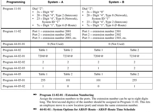
Program 11-02-01 : Extension NumberingAssign the extension numbers to the ports. The extension number can be up to eight digits long. The first/second digit(s) of the number should be assigned in Program 11-01. This lets an employee move to a new location (port) and retain the same extension number.
➻
44-01-01 : System Options for ARS/F-Route - ARS/F-Route Time ScheduleSet this option to ‘0’ so that the F-Route table selected is determined only by the digits dialed without any relation to the day or time of the call.
➻
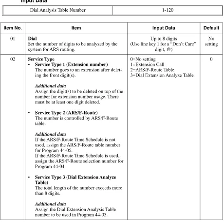
44-02-01 : Dial Analysis Table for ARS/F-Route Access - DialSet the number of digits to be analyzed by the system for ARS routing. Using the 4-digit extension number example in Program 11-01-01, the entry would be: Analysis Table 1: 720@@; Analysis Table 2: 723@@.
➻
44-02-02 : Dial Analysis Table for ARS/F-Route Access - Service TypeSelect the Service Type (0=no setting, 1=extension call, 2=ARS/F-Route table, 3=Dial extension analyze table). Using the 4-digit extension number example in Program 11-01-01, the entry would be: Analysis Table 1: 2 (ARS/F-Route table); Analysis Table 2: 2 (ARS/F-Route table).
➻
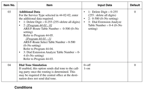
44-02-03 : Dial Analysis Table for ARS/F-Route Access - Additional DataEnter the additional data required for the service type selected in Program 44-02-02, either the number of digits to be deleted or the table number to be used. Using the 4-digit extension number example in Program 11-01-01, the entry would be: 1 (delete 1 digit).
Programming System – A System – B
Program 11-01 Dial “2”:
• 2x = Digit “0”
• 20 = Digit “4”, Type 2 (Intercom)
• 23 = Digit “4”, Type 8 (Network),
System ID “1”
• 7x = Digit “1”, Type 6 (F-Route)
Dial “2”:
• 2x = Digit “0”
• 20 = Digit “4”, Type 8 (Network),
System ID “1”
• 23 = Digit “4”, Type 2 (Intercom)
• 7x = Digit “1”, Type 6 (F-Route)
Program 11-02 Port 1 = extension number 2001
Port 2 = extension number 2002 Port 3 = extension number 2003, etc.
Port 1 = extension number 2301 Port 2 = extension number 2302 Port 3 = extension number 2303, etc.
Program 44-01-01 0 (Not Used) 0 (Not Used)
Program 44-02 Table 1 Table 2 Table 1 Table 2
Program 44-02-01 720@@ 723@@ 720@@ 723@@
Program 44-02-02 2 2 2 2
Program 44-02-03 1 2 1 2
Program 44-05 Table 1 Table 2 Table 1 Table 2
Program 44-05-01 255 101 101 255
➻
44-02-04 : Dial Analysis Table for ARS/F-Route Access - Dial Tone SimulationIf enabled (1), this option sends dial tone to the calling party once the routing is determined. This may be required if the central office at the destination does not send dial tone. Using the 4-digit extension number example in Program 11-01-01, the entry would be: 0 (disabled).
➻
44-05-01 : ARS/F-Route Table - Trunk Group NumberSelect the trunk group number to be used for the outgoing ARS call (0-100, 101-150, 255 [0 = No setting, 101-150 = Networking, 255 = Extension Call]). Using the 4-digit extension num-ber example in Program 11-01-01, the entry would be: ARS/F-Route Table Numnum-ber 1: Priority Number 1, Trunk Group = 255; ARS/F-Route Table Number 2: Priority Number 1, Trunk Group = 101.
➻
44-05-02 : ARS/F-Route Table - Delete DigitsEnter the number of digits to be deleted from the dialed number (0-255 [255 = Delete all]). Using the 4-digit extension number example in Program 11-01-01, the entry would be: ARS/ F-Route Table Number 1: Priority Number 1, Delete Digits = 1; ARS/F-Route Table Number 2: Priority Number 1, Delete Digits = 0.
➻
44-05-03 : ARS/F-Route Table - Additional Dial Number Table-Features
Section 2
-Network Settings and Operation
ARS/F-Route
When dialing the F-Route access code in an extension’s own system which is specified as Routing to Networked system (Group 101-150), calls will be routed to the target system. The call will then be analyzed by the F-Route table in the target system. As a result, the call will be analyzed for the following:
● Outgoing call from trunk
● Extension access call
● Access to the other system
● No defined dial
Compared With Single System Configuration
In a single system with F-Route used, the dialing is analyzed when the call is initially dialed.
Operation
With the sample programming shown below, dialing the F-Route access number, which is defined in the F-Route table (811300), the system calls extension number 300 within System 1 (System ID 1). The telephone’s display initially indicates the F-Route number in progress, then changes to appear as an normal intercom call.
(Sample Programming)
Refer to the Aspire Software Manual (P/N 0893200) for complete description and programming information for the following featues. The information detailed here
applies only to the feature when used in a Networked system.
Kind of setting System 1 System 2
PRG11-01-01
System Numbering
Dial “7”
Digit “1” (1 digit) Type “6” (F-Route)
Dial “7”
Digit “1” (1 digit) Type “6” (F-Route)
PRG44-02-Dial analysis table for F-Route access
01 “711300”
“711@@@” (using wildcard) is available.
“711300”
“711@@@” (using wildcard) is available.
02 “2” (F-Routing) “2” (F-Routing)
03 Add Code = “1” Add Code = “1”
PRG44-05-System Numbering
01 F-Route table-1
Trunk Group No. “101” (Route to System ID 1)
F-Route table-1 Trunk Group “255” (Route to Intercom)
Barge In
Barge In is available in the Networking feature with the following options:
● Barge into a conversation between an extension’s own system and a networked system
● Barge into a conversation between callers in a networked system
● Barge into a call between two networked systems
Barge In can be used in either Monitor Mode (Silent Monitor) or Speech Mode (determined in Program 20-13-10).
Barge In cannot barge into calls across the network in the following instances:
● Conference calls
● Off hook signaling a telephone in the other system
● Barge into an extension’s call without first calling the busy extension in the other system
Operation
To Barge In after calling a busy extension:
The call must be set up for about 10 seconds before you can Barge In. Listen for busy/ring or busy tone.
1. Call busy extension.
2. Press Barge In key (PGM 15-07 or SC 851: 34).
Program Number Title
11-01 Numbering Plan
44-01 System Options for F-Route Service
44-02 Dial Analysis Table for F-Route Access
44-04 F-Route Selection for time schedule
44-05 F-Route Table
44-06 Additional Dial Table
44-07 Gain Table for F-Route Access
44-08 Time Schedule for F-Route Service
44-09 Weekly Schedule for F-Route Service
Related Programs
Call Forwarding
Call Forwarding Immediate / Busy / No Answer / Busy-No Answer / Both Ring options are avail-able with the Networking feature.
With a networked system, when Call Forwarding enabled, there is a slight difference in the tele-phone’s display. With a single system, the extension name is displayed on the extension which has Call Forwarding. With a networked system, the extension number is displayed.
Operation
To activate or cancel Call Forwarding:
To activate or cancel Call Forwarding:
1. Press idle CALL key (or lift handset) + Dial *2 .
OR
Press Call Forwarding key (PGM 15-07 or SC 851: code 16).
2. Dial Call Forwarding condition:
1 = Personal Answering Machine Emulation (then skip to step 4 - refer also to “Voice Mail”). 2 = Busy or not answered
4 = Immediate 6 = Not answered
7 = Immediate with simultaneous ringing (not for Voice Mail) 0 = Cancel
3. Dial destination extension, Voice Mail master number or press Voice Mail key.
4. Dial Call Forwarding type:
2 = All calls
3 = Outside calls only 4 = Intercom calls only
When you enable Call Forwarding, your Call Forwarding key flashes slowly. If you don’t have a Call Forwarding key, DND flashes slowly.
Your DND or Call Forwarding (Station) Programmable Function Key flashes when Call Forwarding is activated.
OR
Program Number Title
11-12-08 Service Code Setup (for Service Access) - Barge In
11-16-02 One Digit Service Code Setup - Barge In
20-13-15 Class of Service Options (Supplementary Service) - Barge In, Initiate
20-13-16 Class of Service Options (Supplementary Service) - Barge In, Receive
20-13-17 Class of Service Options (Supplementary Service) - Barge In Tone/
PGM 15-07 or SC 851: code 10 for Forward All Calls Immediately PGM 15-07 or SC 851: code 11 for Forward when Busy
PGM 15-07 or SC 851: code 12 for Forward when Unanswered PGM 15-07 or SC 851: code 13 for Forward Busy/No Answer PGM 15-07 or SC 851: code 14 for Forward with Both Ringing PGM 15-07 or SC 851: code 15 for Follow Me
PGM 15-07 or SC 851: code 16 for Forward to Station (forward type is selected at the time the option is set by the user)
PGM 15-07 or SC 851: code 17 for Forward to Device
2. Dial 1 plus extension to enable; dial 0 to disable.
Once you activate Call Forwarding, only your Call Forwarding destination can place an Intercom call to you.
3. Dial destination extension, Voice Mail master number or press Voice Mail key.
You’ll hear stutter dial tone when placing a new call.
Your Call Forwarding Programmable Function Key flashes when Call Forwarding is activated.
Related Programs
Call Forwarding / Do Not Disturb Override
The extension user may be able to call an extension which has Call Forwarding or Do Not Disturb set.
Operation
To override an extension’s Call Forwarding or Do Not Disturb:
1. Call the forwarded or DND extension.
2. Press Override key (PGM 15-07 or SC 851: 37).
Program Number Title
11-11-01 Service Code: Call Forward – Immediate
11-11-02 Service Code: Call Forward – Busy
11-11-03 Service Code: Call Forward – No Answer
11-11-04 Service Code: Call Forward – Busy/No Answer
11-11-05 Service Code: Call Forward – Both Ring
11-11-06 Service Code: Call Forwarding (Select Option)
20-11-01 Call Forward – Immediate Class of Service
20-11-02 Call Forward – Busy Class of Service
20-11-03 Call Forward – No Answer Class of Service
Related Programs
Call Forward, Off-Premise
Off-Premise Call Forwarding allows an extension user to forward their calls to an off-site location. This feature works the same in a networked system as it ddoes a single system.
Operation
To activate Call Forwarding Off-Premise
1. At keyset, press idle CALL key + Dial *4 .
OR
Press Call Forward (Device) key (PGM 15-07 or SC 851: 17) OR
At SLT, lift handset Dial *4 .
2. Dial 6 + trunk access code.
Trunk access codes are 9 (ARS/Trunk Group Routing), 804 + Line Group (1-9, 01-99 or 001- 100) or #9 + Line number (e.g., 05 or 005 for line 5.
3. Dial the outside number to which your calls should be forwarded.
4. (Keyset only) Press HOLD.
5. Press SPK (or hang up at SLT) to hang up if you dialed *4 in step 1.
Your DND or Call Forwarding (Device) Programmable Function Key flashes.
To cancel Call Forwarding Off-Premise
1. At keyset, press idle CALL key + Dial *4 .
OR
Press Call Forward (Device) key (PGM 15-07 or SC 851: 17) OR
At SLT, lift handset and dial *4 .
2. Dial 6 + HOLD.
3. Press SPK (or hang up at SLT) to hang up if you dialed *4 in step 1.
Your DND or Call Forwarding (Device) Programmable Function Key stops flashing.
Program Number Title
11-12-01 Service Code Setup (for Service Access) : Call Forwarding / Do Not
Disturb Ovveride
11-16-06 Single Digit Service Code Setup : DND/Call Forward Override
15-07-01 Programming Function Keys
20-06-01 Class of Service for Extensions
20-13-04 Class of Service Options (Supplementary Service) - Call Forwarding/
Call Forwarding with Follow Me
The extension user can program Call Forward Follow-Me to extension in a networked system. When the extension with the Follow Me setting receives an incoming call, both the original exten-sion and the programmed destination extenexten-sion starts ringing.
With a networked system, when Call Forward Follow-Me is enabled, there is a slight difference in the telephone’s display. With a single system, the destination extension displays the extension name for the phone with Follow-Me enabled. With a networked system, the extension number is displayed.
Operation
To activate Call Forward Follow Me:
1. At a keyset other than your own, press idle CALL key and dial *2 .
OR
Press Call Forward (Station) key (PGM 15-07 or SC 851: 15). OR
At SLT other than your own, lift handset and dial *2 .
2. Dial 3 + Dial your own extension number (i.e., the source).
3. Dial Call Forwarding Type:
2 = All Calls
3 = Outside calls only 4 = Intercom calls only
4. SPK (or hang up at SLT) if you dialed *2 in step 1.
Your Call Forwarding (Station) Programmable Function Key flashes when Call For-warding is activated.
To cancel Call Forward Follow Me:
1. At keyset, press idle CALL key and dial *2 .
OR
Press Call Forward (Station) key (PGM 15-07 or SC 851: 15). OR
At SLT, lift handset and dial *2 .
2. Dial 0.
3. SPK (or hang up at SLT) if you dialed *2 in step 1.
Your Call Forwarding (Station) Programmable Function Key goes out.
Program Number Title
13-01 Abbreviated Dial Function Setup
14-05 Trunk Group
14-06 Trunk Group Routing
21-02 Trunk Group Routing for Extensions
Related Programs
Call Waiting / Camp On
With Call Waiting, an extension user may call a busy extension and wait in line (Camp-On) without hanging up. When the user Camps-On, the system signals the busy extension with two beeps indi-cating the waiting call. The call goes through when the busy extension becomes free. Call Waiting helps busy extension users know when they have additional waiting calls. It also lets callers wait in line for a busy extension without being forgotten.
With a networked system, camping on to an idle extension and Trunk Queuing/Camp On for a trunk port are not supported.
With a networked system, when Call Waiting/Camp On is enabled, there is a slight difference in the telephone’s display. With a single system, the target extension’s name is displayed on thephone which has enabled Call Waiting. With a networked system, the extension number is displayed.
Operation
To Camp-On to a busy extension:
1. Call busy extension.
2. Dial 2 or press Camp-On key (PGM 15-07 or SC 851: 35).
3. Do not hang up.
To Camp-On to a trunk, see Trunk Queuing.
To cancel a Camp-On request:
1. Hang up.
2. At keyset, press idle CALL key and dial 870.
OR
At keyset, press Camp-On key (PGM 15-07 or SC 851: 35). OR
At single line set, lift handset and dial 870.
Related Programs
Program Number Title
11-11-07 Service Code of Follow Me
11-11-06 Call Forwarding (Select Option)
Program Number Title
11-12-05 Service Code: Setting Camp On
11-12-06 Service Code: Cancelling Camp On
Caller ID Display
Caller ID information can be sent to incoming target extension in a networked system and show the Caller ID on the phone’s display. The ABB Name is also shown on LCD by searching ABB table.
Caller ID, however, cannot be shown in a networked system for incoming trunks defined as normal (0) in Program 22-02.
Operation
No change.
Related Programs
➻
20-09-02 : Class of Service Options (Incoming Call Service) - Caller ID DisplayDefine the option whether display Caller ID or not in each station port.
➻
20-09-02 : Class of Service Options (Incoming Call Service) - Sub-Address IdentificationDefine whether an extension displays the Caller Sub-Address.
Item
No. Item
Input data
Default
COS
01-14 COS 15
02 Caller ID Display
Enables/disables the Caller ID display at an extension.
0-Off 1-On
0 0
Item
No. Item
Input data
Default
COS
01-14 COS 15
03 Sub Address Identification
Define whether an extension displays the Caller Sub-Address.
0-Off 1-On
➻
13-04 : Abbreviated Dialing Number and NameDefine the abbreviated dialing number and name. The ABB name will be shown on a phone’s LCD when the ABB table has a matching number with the incoming Caller ID. The common abbreviated number table is used to search for a match.
Central Office Calls, Placing: Seizing a trunk in a networked system
The system allows a user to seize a trunk in a networked system using the following methods:Related Programs
The following example indicates the setting required to seize the trunk in a networked system (Extension in System A tries to make an external call using a trunk in System B).
Item
No. Item Input Data Default
01 Abbreviated Dialing
Data
1-9, 0, *, #,
Pause (Press line key 1),
Recall/Flash (Press line key 2),
@ for Additional Digit for ISDN
Functionality (Press line key 3)
(max. 24 digits)
No Setting
02 Name Max. 12 Characters No Setting
Method of Outgoing Available Note
Specified Trunk Access (#9 + the trunk number) N
Specified Trunk Group Access (804 + group number) N
Trunk Route Access (9) Y
ARS/F-Route See ARS/F-Route
Program System – A System – B
Program 14-06-01
Trunk Group Routing
Route 1
101 (Route to SystemID 1)
Route 1
1 (Route to Trunk Group 1)
Program 21-02-01
Trunk Group Routing for Extensions
Extension 301 (which make a call via networking)
1 (Route 1)
This setting is referenced in Program 14-06-01
Program 21-16-01
Trunk Group Routing for Networking
System ID 1 Route 1
Conference
The user can create a Conference call to include a user in a networked system.
Operation
To establish a Conference:
Keyset
1. Establish Intercom or trunk call.
2. Press CONF or Conference key (PGM 15-07 or SC 851: 07).
3. Dial extension you want to add.
OR
Access outside call OR
Retrieve call from Park orbit.
To get the outside call, you can either press a line key or dial a trunk/trunk group code. You can optionally go back to step 2 to add more parties to your Conference.
4. When called party answers, press CONF or Conference key twice.
If you cannot add additional parties to your Conference, you have exceeded the sys-tem’s Conference limit.
5. Repeat steps 2-4 to add more parties.
Single Line Set / 2-Button Telephone
1. Establish Intercom or trunk call.
2. Single Line Set Hookflash and dial #1. 2-Button Telephone Press HOLD and dial #1.
3. Dial extension you want to add.
OR
Access trunk call. OR
Retrieve call from Park orbit. 4. Single Line Set
Hookflash and repeat step 3 to add more parties. OR
Hookflash twice to set up the Conference. 2-Button Telephone
Press HOLD and repeat step 3 to add more parties. OR
Press HOLD twice to set up the Conference.
Related Programs
Department Calling
Department Group access is available via Networking. When the extension at System A tries to make a Department Call to System B, System A should have a numbering plan which defines the Department Access code at System-B (must be defined as dial type 8, Networking in Program 11-01 : System Numbering).
The following Department Calling options are supported with the Networking feature.
Operation
1. When dialing the Department access code for the networked system, the call is dialed in the
the same way as the networking access code dialing the networked system.
2. A Department Call from the outgoing system will be routed to an available extension in the
Department Group.
Program Number Title
15-07-01 Programming Function Keys - Conference (code 07)
20-06-01 Calls of Service for Extensions
20-13-08 Class of Service Options (Supplementary Service) - Conference
Program Number Mode Same as Single System
16-01-02 Department Calling Cycle Yes
16-01-03 Department Routing When Busy Yes
16-01-04 Hunting Mode No
16-01-05 All Ring Mode When a call is transferred to a
Department Group with All Ring, there is a difference in operation. In a single system, an extension within the same system can transfer a call to a Department Group and the call will ring an extension within the Depart-ment Group once the transferring user hangs up. In a networked sys-tem, the transfer will not go through and the call will recall the extension performing the transfer.
16-01-06 STG Withdraw Mode No
16-01-07 Call Recall Restriction for STG No
16-01-08 Maximum Queuing Number No
Department Step Call
After calling a busy Department Calling Group member in a networked system, an extension user can have Department Step Calling Quickly call another member in the group.
Operation
To make a Step Call:
You step through Extension Groups set in Program 16-02.
1. Place call to busy Department Group member.
OR
Place call to Department Group pilot number.
2. Dial #.
OR
Press Step Call key (PGM 15-07 or SC 851: 36).
3. Repeat step 2 to call other Department Group members.
Related Programs
Program Number Title
11-07-01 Department Group Pilot Numbers
16-01 Department Group Basic Data Setup
16-02-01 Department Group Assignment for Extensions
22-07-01 DIL Assignment
Program Number Title
11-12-07 Service Code Setup (for Service Access) - Step Call
11-16-01 Single Digit Service Code Setup - Step Call
20-06-01 Class of Service for Extensions
20-08-12 Class of Service Options (Outgoing Call Service) - Department Step
Direct Inward Dialing (DID)
An incoming DID call can be routed to an extension in a networked system.
Operation
For incoming DID calls, the system refers to Program 22-11 : DID Translation Number Conversion to determine how to route the call. If the number is determined to be in the networked system, the call will be routed to the proper system node.
The timer value is determined by the system data at the incoming trunk side if the incoming DID call is transferred to a ring group due to the no-answer timer expiring.
Related Programs
Direct Inward Line (DIL)
A Direct Inward Line (DIL) is a trunk that rings an extension, virtual extension or Department Group directly. Since DILs only ring one extension or group (i.e., the DIL destination), employees always know which calls are for them. For example, a company operator can have a Direct Inward Line for International Sales Information. When outside callers dial the DIL’s phone number, the call rings the operator on the International Sales line key. The DIL does not ring other extensions.
The outside party can call an extension at a networked system, if the DIL trunk is set to route to the other system.
Operation
1. An outside caller places a call to a DIL trunk.
2. The call will be routed to the networked system if the DIL target is defined as an extension in
the networked system in Program 22-07 : DIL Assignment.
Related Programs
Program Number Title
22-02 Incoming Service Type
22-09 DID Basic Data Setup
22-10 DID Conversion Area Setup
22-11 DID Conversion Table Data Setup
22-12 DID Transferred Destination Setup
Program Number Title
22-02 Incoming Service Type Setup
22-07 DIL Assignment
Direct Inward System Access (DISA)
Networking allows DISA callers to place a call to an extension in a networked system. Some sys-tem features can also be accessed from the networked syssys-tem. The Class of Service is determined by the password entered by the DISA caller. The password table is referred to by the system on the incoming trunk side.
The Networking feature allows the following DISA services as allowed in Program 20-14 : Class of Service Options for DISA/E&M.
Operation
To place a DISA call into the system (from any 2500 type telephone):
1. Dial the telephone number that rings the DISA trunk.
2. Wait for the DISA trunk to automatically answer with a unique dial tone.
3. Dial the 6-digit DISA password (access code).
4. Wait for a second unique dial tone.
5. Dial an extension (301-556).
OR
Dial 9 for Trunk Group Routing or ARS. OR
Dial Alternate Trunk Route Access Code (if enabled). OR
Dial #9 + a trunk number (1-200) for an outside call. OR
Dial 0 for the operator. OR
Dial 803 + an External Paging Zone number (1-8 or 0 for All Call).
If the received digits are analyzed as a networked extension number, the call is routed to the proper network node.
Program Number Service Name Available
20-14-02 Trunk Route Access Yes
20-14-03 Trunk Group Access No
20-14-04 Common Abbreviated dialing No
20-14-05 Operator access Yes
20-14-06 Internal Paging No
20-14-07 External Paging Yes
20-14-08 Specified trunk access No
20-14-09 Forced trunk disconnect No
20-14-10 Call Forward setting No
Related Programs
Hold
This feature is available with no changes in programming or operation.
Program Number Title
20-14 Class of Service Options for DISA/E&M
22-02 Incoming Service Type Setup
25-01 DID/DISA Line Basic Data Setup
25-02 DID/DISA VRS Error Message
25-03 DID/DISA Transfer Ring Group with Incorrect Dialing
25-04 DID/DISA Transfer Ring Group with No Answer/Busy
25-05 DID/DISA Error Message Setup
25-06 DID/DISA One-Digit Code Attendant Setup
25-07 System Timers for DID/DISA
25-08 System timer for DID/DISA Service
25-09 Class of Service for DISA User
25-10 Trunk Group Routing for DISA
25-11 Toll Restriction Class for DISA
25-12 Individual Trunk Group Routing for DISA
Hotline / Direct Station Selection (DSS)
An extension user can have a Hotline key to a networked extension. The Hotline or DSS console keys can display the status lamp indication of an extension in a networked system. The lamp status, however, is not displayed in real time and is updated at the interval defined in system programming.
Only shows the status of an extension at other system. Lamp status is not update in real time. Status will be updated in the time interval specified in Program 20-01-04.
Operation
To place a call to your Hotline partner:
1. Press Hotline key (PGM 15-07 or SC 851: 01 + partner’s extension number)
You can optionally lift handset after this step for privacy.
To transfer your outside call to your Hotline partner:
1. Press Hotline key.
2. Announce call and hang up.
OR
Hang up to have the call wait at your Hotline partner unannounced.
If unanswered, the call recalls like a regular transferred call.
To answer a call from your Hotline partner:
1. If you hear two beeps, speak toward phone.
OR
1. If your telephone rings, lift handset.
Calling an extension from your DSS Console:
1. (Optional for 110-Button Consoles) Press EXT.1 or EXT.2 to select the range.
2. Press DSS Console key.
If the call voice-announces, you can make it ring by dialing 1. If you don’t have Handsfree, you must lift handset to speak.
Related Programs
Program Number Title
20-01-04 System Options - Network BLF Indication
20-02-03 System Options for Multi-Line Telephones - BLF Control
20-13-06 Class of Service Options (Supplementary Service) - Automatic Off Hook
Signaling
20-06-01 Class of Service for Extensions
Intercom
An extension user can make an intercom call to a networked system if the networked extensions are defined with the Network Access Code (Program 11-01, Dial Type = 8)
A user can change the signaling type for the intercom call they place to either a voice announce or ringing call to extension in a networked system.
Operation
To place an Intercom call:
1. At keyset, press idle CALL key.
OR
At single line telephone, lift handset.
2. Dial extension number (or 0 for your operator).
Your call may voice-announce or ring the called extension. Dial 1 to change the way your call alerts the called extension.
If the extension you call is busy or doesn’t answer, you can dial another extension without hanging up.
Related Programs
Program Number Title
11-12-06 Service code of Voice/Signal Change
11-16-03 One digit service code of Voice/Signal Change
20-06-01 Class of Service for Extensions
Last Number Redial
Last Number Redial allows an extension user to quickly redial the last number dialed. When used with a networked system, the system can use the same trunk on which the call was originally placed, even if the trunk is a trunk in another system.
Operation
To redial your last call:
1. Without lifting the handset, press LND.
The last dialed number is displayed.
2. To redial the last number, press #.
OR
Search for the desired number from the Redial List by pressing the LND or VOLUME ▲ or
VOLUME ▼ keys.
3. Lift the handset or press SPK to place the call.
The system automatically selects a trunk from the same group as your original call and dials the last number dialed.
OR
1. At keyset, press idle line key (optional).
The system automatically selects a trunk from the same group as your original call.
2. Press LND.
OR
1. At keyset, press idle CALL key.
OR
At single line telephone, lift handset.
2. Dial #5.
The system automatically selects a trunk from the same group as your original call and dials the last number dialed.
Related Programs
Program Number Title
11-12-12 Service Code Setup (for Service Access) - Last Number Dial
15-02-13 Multi-Line Telephone Basic Data Setup - Redial List Mode
Message Waiting
This feature can be used when placing an intercom call to a networked extension and receives either no answer or hears a busy tone.
With a networked system, when a Message Waiting has been left, there is a slight difference in the tele-phone’s display. With a single system, the extension’s name which left the message is displayed. With a networked system, the extension number is displayed.
Operation
To leave a Message Waiting:
1. Call busy or unanswered extension.
2. Dial 0 or press Message Waiting key (PGM 15-07 or SC 851: 38)
3. Hang up.
With keyset phones, the MW LED lights.
To answer a Message Waiting:
When you have a message, your MW LED flashes fast for keysets.
1. At a keyset, press idle CALL key and dial *0.
OR
Press Message Waiting key (PGM 15-07 or SC 851: 38). OR
At single line telephones, lift the handset and dial *0.
If the called extension doesn’t answer, dial 0 or press your Message Waiting key to automatically leave them a message.
Normally, your MW LED goes out. If it continues to flash, you have new messages in your “Voice Mail” mailbox or a new “General Message”. Go to “To check your messages” below.
Related Programs
Program Number Title
11-11-09 Service Code Setup (for Setup/Entry Operation) - Answer Message
Waiting
11-11-10 Service Code Setup (for Setup/Entry Operation) - Cancel All Messages
Waiting
11-11-11 Service Code Setup (for Setup/Entry Operation) - Cancel Message
Waiting
11-16-07 Single Digit Service Code Setup: Message Waiting
Paging
An extension user can make internal or external pages to a networked system. Paging to a net-worked system can only be activated by dialing a service code and the target network’s system ID.
Operation
To Make an Internal Page
1. Dial 801.
2. Dial # and the system ID.
The system ID must be dialed as 2 digits (ex: #02).
3. Dial the Paging Zone number (00-64).
Dialing 00 calls All Call External Paging.
4. Make announcement to the networked system.
5. Press SPK to hang up.
To Make an External Page
1. Dial 803.
2. Dial # and the system ID.
The system ID must be dialed as 2 digits (ex: #02).
3. Dial the Paging Zone number (0-9).
Dialing 0 calls All Call Internal Paging.
4. Make announcement to the networked system.
5. Press SPK to hang up.
To Make a Combined Page
1. Dial *1.
2. Dial # and the system ID.
The system ID must be dialed as 2 digits (ex: #02).
3. Dial the Paging Zone number (0-9).
Dialing 0 calls All Call Combined Paging.
4. Make announcement to the networked system.
Related Programs
Park
Park places a call in a waiting state (called a Park Orbit) so that an extension user may pick it up. Any extension user who is in the same Park Group as the extension which placed the call in Park can answer the call. This includes extension users in a networked system. For example, when an extension user in Park Group 3 within System A places a call in Park, the extension users in Park Group 3 at any connected system can retrieve the call by pressing the flashing park key or dialing a service code.
With a single system, when two users within the same Park Group try to place a call in the same page zone at the same time, one user will get the zone while the other user’s call will either ring back or it will remain an active call, depending on how the park zone was accessed. With Network-ing, if both users try to access the same zone, one user will get the zone, while the other will hear ringback, at which time they can park the call in a different zone.
Operation
To Park a call in a system orbit:
You can Park Intercom or trunk calls.
1. Press Park key (PGM 15-07 or SC 852: *04 + orbit).
The Park key LED lights.
If you hear busy tone, the orbit is busy. Try another orbit.
2. Use Paging to announce call.
3. Press SPK to hang up.
If not picked up, the call will recall to you.
OR
1. At keyset or 2-Button telephone, press HOLD.
OR
At a 500/2500 single line telephone, hookflash.
2. Dial #6 and the Park orbit (1-64).
If you hear busy tone, the orbit is busy. Try another orbit.
Program Number Title
11-12-19 Service Code Setup (for Service Access) - Internal Group Paging
11-12-20 Service Code Setup (for Service Access) - External Paging
11-12-24 Service Code Setup (for Service Access) - Combined Paging
31-01 System Options for Internal/External Paging
31-02 Internal Paging Group Assignment
31-03 Internal Paging Group Settings
31-04 External Paging Zone Group
4. Press SPK to hang up.
If not picked up, the call will recall to you.
Note: The parked call recalls after the Park Hold Time (Program 24-01-06). The call rings the extension to which it recalled for the Hold Recall Callback Time (Program 24-01-02). The call then goes on Hold for the Park Hold Time - then recalls again for the Hold Recall Callback Time. The call continues to cycle between Hold and recall until the extension user answers the call or the outside party hangs up.
To pick up a parked call:
1. Lift handset.
2. Press Park key (PGM 15-07 or SC 852: *04 + orbit).
OR
1. At keyset or 2-Button telephone, press idle CALL key.
OR
At single line telephone, lift handset.
2. Dial *6 and the Park orbit (1-64).
Related Programs
Ringdown Extension, Internal/External
A networked system can have a phone defined as a Ringdown Extension to dial either an internal or external number.
Operation
To place a call if your extension has ringdown programmed:
1. Lift handset.
If you want to place a trunk call, press a line key before lifting the handset.
Depending on the setting of your ringdown timer, you may be able to dial an Intercom call before your ringdown goes through.
If the destination has Handsfree Answerback enabled, your call will voice announce.
Program Number Title
11-12-31 Service Code Setup (for Service Access) - Placing a Call in Park
11-12-32 Service Code Setup (for Service Access) - Retrieving Call from Park
20-11-19 Class of Service Options (Hold/Transfer Service) – Normal/Extended Park
If enabled, the recall timer set in Program 24-01-07 is used. If this option is disabled, the timer in Program 24-01-06 is used.
24-01-06 System Options for Hold - Park Hold Recall Timer – Normal
24-01-07 System Options for Hold - Park Hold Recall Timer – Extended