YOUNG, ERIC STEPHEN. Ultrasound-Based Biomedical Implantable Device. (Under the direction of Dr. Ömer Oralkan and Dr. George Ligler).
A diverse set of stimulators, transducers and data transceivers can be integrated into
medically implantable devices using ultrasonic power. An application for such a device is
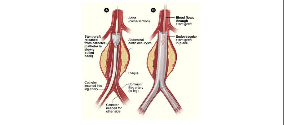
postoperative monitoring of abdominal aortic aneurysm repair. Endoleaks are a potentially
serious, but correctible, complication of aorta repair. A miniscule ultrasonic powered device
incorporated into the stent-graft for endovascular delivery could provide on demand diagnostic
information about the presence of endoleak by monitoring the dimensions of the aneurysm sack
and/or stent-graft in real time. In this work, a wireless ultrasonic power recovery scheme is
demonstrated in oil using a single-element capacitive micromachined ultrasonic transducer, and a
circuit made with commercially off-the-shelf discrete components. The 2-mm diameter CMUT
element, a diode rectifier bridge and inductor-based boost circuit form the power conversion
circuit delivering over 1 mW to the load. Other aspects of the implantable device that have been
demonstrated are a pulse echo measurement of the diameter of the endovascular aneurysm repair
device lumen, and a data transmission method that encodes clock, data and transmission framing
information in biphasic ultrasonic pulses and takes advantage of the wideband characteristics of
the CMUT. This proof of concept is guiding the design of an integrated circuit implementing the
key elements of the implantable device: wireless power, data uplink and clinical measurement.
For a compact solution and to facilitate translation, the integrated circuit version will accomplish
© Copyright 2020 by Eric Stephen Young
by
Eric Stephen Young
A thesis submitted to the Graduate Faculty of North Carolina State University
in partial fulfillment of the requirements for the degree of
Master of Science
Biomedical Engineering
Raleigh, North Carolina 2020
APPROVED BY:
_______________________________ _______________________________ Ömer Oralkan George Ligler
Committee Co-Chair Committee Co-Chair
ii
DEDICATION
I started the pursuit of this degree, and this research topic, to make an impact on
healthcare - leveraging 25 years of industry experience in electronics, integrated circuit design
and engineering. The combination of medicine with engineering is for me the fusion of my
upbringing among the medical community which dominated the first half of my life, and the
mature years of my life spent in a career applying electronics technology to provide solutions in
consumer, automotive and industrial applications. I hope the tiny contribution described in this
thesis will improve accessibility, cost and clinical outcomes in healthcare.
I would like to dedicate this work to my family: that is to my parents (Dr. Stephen
Young, and Dr. Margaret Young), wife (Melinda) and children (Zachary, Benjamin, Marie, Isaac
and Hannah). Thank you all for giving me the inspiration to leverage the present to fuse the
future (yours and mine) with the past; and hopefully my work will be relevant for years to come
in a rapidly changing world.
iii
BIOGRAPHY
Eric Young was born in Galveston, TX in 1968. His parents were medical doctors, so he
grew up around the medical college and around patient care in the days when children could tag
along with their parents on rounds or procedures. After earning a BS in Nuclear Engineering at
Purdue University he worked for the Department of Energy as a headquarters-based engineer for
the nuclear and accelerator facilities used to certify electronics for exposure to harsh radiation
environments. Motivated by the opportunities he saw in electronics, he returned to graduate
school at University of Maryland in electrical engineering in 1995. Eric married Melinda in
1996, finished the MS degree and saw the birth of their first child in 1997. In 20 years of
industry work at Atmel, Motorola, Maxim and Linear Technology he has contributed to the
heady early days of field programmable gate arrays, automotive airbag deployment systems,
cellphone power management circuits, general purpose switch-mode circuits for DC-DC power
conversion, and automotive/industrial LED drivers. During those years, Eric and Melinda have
had five more children, and have resided for the majority of that time in Apex, NC. In late 2017,
after the close of the purchase of the company he worked for, Linear Technology, by Analog
Devices, Eric decided it was a good opportunity to return to school to broaden his horizons
beyond switch-mode power to include many new technologies, with a focus on healthcare. He
was admitted to the UNC-NCSU Joint Department of Biomedical Engineering starting in August
2018. He accepted an engineering position in industry at Analog Devices, starting in December
iv
ACKNOWLEDGMENTS
I would like to acknowledge my research advisor, Dr. Ömer Oralkan, for supporting my
application to the graduate school in UNC-NCSU Joint Department of Biomedical Engineering,
and for taking on my unique case by sponsoring this research in his group as a Research
Assistant. The application idea he paired me with leveraged my experience with power
conversion and circuits, and allowed me to exercise my newly gained knowledge in ultrasonics
and biomedical electronics. I appreciate that my assignments in the IMIST group, and even
before joining the graduate program, as a student in his class on MEMS devices, have allowed
steady progress towards the goal of demonstrating this implantable device concept that uses
capacitive machined ultrasonic transducers. Thanks also to the graduate and postdocs in the
IMIST group who helped me with the lab software and setting up experiments, including Dr. F.
Yalcin Yamaner, Jeanne Sanders, Marzana Mahmud, Chunkyun Seok, and Ali Onder Biliroglu.
This work was supported by the National Science Foundation under Grant 1160483 as
part of a Center-to-Centre collaborative partnership with NUI Galway, Ireland and Queens
University, Belfast, Northern Ireland. I would like to recognize Sean Cummins from NUI
Galway for the advice he provided based on his role in mechanical design of the delivery system,
and translational studies. The project is administered by the ASSIST center, with Michael
Daniele as overall principal investigator. Dr. Daniele defined the second use of the wireless
implantable, for monitoring ingrafting of an engineered tissue patch for cardiac muscle
regeneration. Without the seed ideas motivating it, and collaboration of the team members, I feel
this work would have been relegated to novelty instead of enabling technology. Thanks to our
industry partner, Cook Medical for providing the EVAR samples used to investigate the
v I would also like to acknowledge the professors who have contributed to the
improvement of my knowledge base with their courses which I attended: Michael Gamcsik,
David Lalush, Greg Trahey, Elaine Bohorquez, Brian Floyd, David Ricketts, and Yaoyao Jia.
Without the encouragement and cameraderie of my fellow biomedical engineering PhD
students from the class of 2018, inside and outside of the classroom, this would have been a
much more difficult and lonely endeavor. I hope to continue working with them in the future;
regardless of the outcome with this work, I wish them the best in all their endeavors.
Finally, I could not have done this career re-tooling without the loving support of my
wife, Melinda. She kept the family running while I worked weekends and nights on the research
and coursework. This uncommon experiment involving breaking off mid-career to pursue
graduate studies, was conducted under the watchful eyes of my children, some of whom wish to
pursue a career in medicine or engineering. It was also observed by my colleagues in industry
through my “blog”. I hope these folks can take away some encouragement about biomedical
vi
TABLE OF CONTENTS
LIST OF FIGURES ... vii
Chapter 1: Introduction ... 1
1.1 Motivation ... 1
1.2 Challenge of a wireless implantable device for deep tissue applications ... 6
1.3 Contribution of this work ... 8
1.4 Thesis Organization ... 8
Chapter 2: Background Information ... 10
2.1 Key Ultrasound Concepts ... 10
2.2 Capacitive Micromachined Ultrasonic Transducer ... 15
Chapter 3: Ultrasonic Wireless Power ... 23
3.1 Power Converter Architecture ... 23
3.2 Experimental Setup ... 24
3.3 Key Results ... 26
Chapter 4: Ultrasonic Wireless Communications ... 28
4.1 Wireless Uplink Considerations ... 28
4.2 Approach ... 29
4.3 Experimental Results ... 30
Chapter 5: Clinical Applications of Wireless Implantable Device ... 33
5.1 Monitoring for Endoleak in EVAR Stent-Graft... 33
5.2 Other Applications ... 35
Chapter 6: Design and Fabrication of Integrated Circuit Implementation ... 37
6.1 Overall Design Objectives ... 37
6.2 Process Selection ... 38
6.3 Schematic Designs and Representative Waveforms ... 38
Chapter 7: Conclusions ... 44
7.1 Thesis Summary... 44
7.2 Future Work ... 46
References ... 50
vii
LIST OF FIGURES
Figure 1. "Neural Dust" uses piezoelectric based ultrasonic power harvesting for neural
recording. ...2
Figure 2. EVAR Procedure showing deployment of stent by catheter ...2
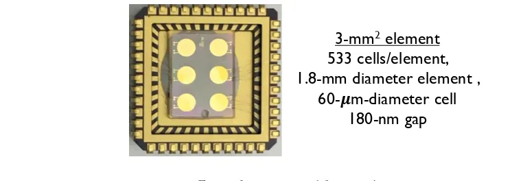
Figure 3. CMUT used for experiments. ...2
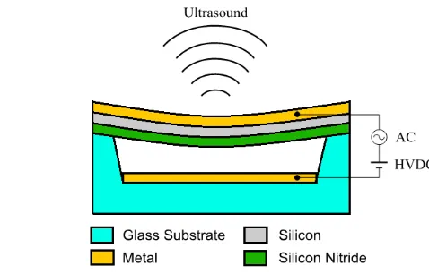
Figure 4. Cross section of CMUT showing key layers ...2
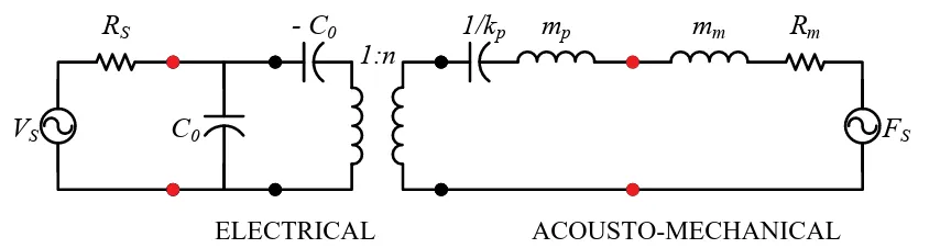
Figure 5. Electrical model of acoustic transducer replacing mechanical terms with electrical elements. ...2
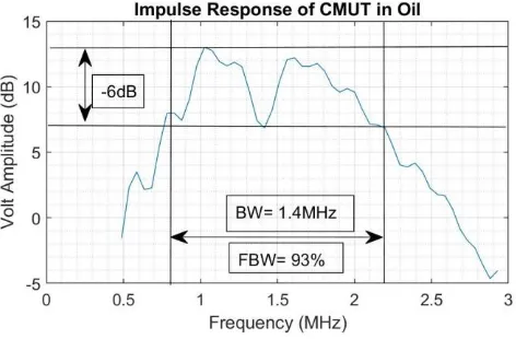
Figure 6. Wideband response (0.75 to 2.2 MHz) of CMUT in oil ...2
Figure 7. Frequency response in air for normal and collapse modes showing high frequency capability of collapse mode. ...2
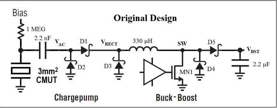
Figure 8. Power converter circuit schematic diagram.. ...2
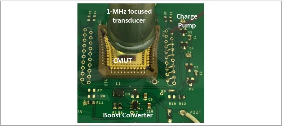
Figure 9. Photo of experimental setup for acoustic converter circuit and transducer. ...2
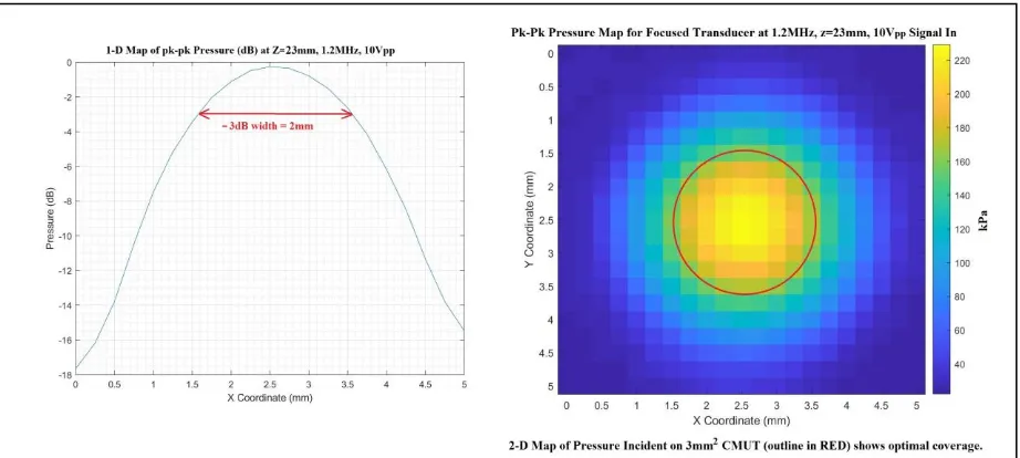
Figure 10. Cross section graph and colormap of pressure seen by CMUT laterally at an axial distance of 23mm ...2
Figure 11. New power recovery circuit schematic uses an active rectifier. Results show a 4x improvement. ...2
Figure 12. Signal flow diagram shows triangular shaped biphasic pulses to transmit side, and sinusoidal biphasic pulses at receiver. ...2
Figure 13. Experimental setup for biphasic pulsed communications, immersed in oil. Two CMUTs used, one each for transmit and receive. The acoustic signal is reflected from the oil-air interface. ...2
Figure 14. Oscilloscope recordings of transmit and receive signals in acoustic biphasic pulse communication ...2
Figure 15. Proposed routine monitoring for EVAR endoleak requires an external handheld unit to transmit power and receive data ...2
viii Figure 17. Application schematic for implantable EVAR monitoring device showing
integrated circuit and external components, noting approximate device sizes ...2
Figure 18. Chargepump rectifier for interface between buck-boost converter and CMUT. Bottom panel shows waveforms of AC signal from CMUT and rectified signal input to buck-boost power stage. ...2
Figure 19. Schematics of low drop active Vcc rectifier and GND clamp circuits. Vcc rectifier captures peak of Vin waveform and provides power for IC startup. Vin ground clamp provides current to inductor during free-wheeling phase of
buck-boost converter. ...2
Figure 20. Schematic of Cockroft-Walton chargepump which has functions to augment
the embedded CMUT bias charge to optimize power conversion ...2
Figure 21. Current and voltage waveforms for the buck-boost converter. ...2
1
CHAPTER 1. Introduction 1.1 Motivation
This work describes proof-of-concept studies for using ultrasound to implement the three
primary functions of a wireless biomedical implantable device: power, communication, and
measurement or therapy. These three functions were demonstrated in isolation from each other,
but with an integrated circuit electronic device they could be combined into a powerful platform
for biomedical monitoring. Using micromachining technology for the transducer and
industrial-scale silicon electronic device technology for the integrated circuit, it is possible to achieve a tiny
heterogeneously integrated device that can be delivered by catheter deep into the tissues to fulfill
some unmet needs in biomedical monitoring and/or therapy. Two potential use cases are
presented involving performance monitoring of tissue grafts, but this is by no means the limit.
Miniscule micropower electronic devices based on ultrasonic technology are ideal for
biomonitoring and bio-stimulation applications which require a very small form factor.
Ultrasound is a proven and a powerful tool to measure key parameters of interest, i.e., distances,
pressures and flows, in various challenging environments. This rich body of diagnostic
information is enabled by the unique characteristics of its coherent energy: the millimeter
wavelengths provide excellent spatial resolution; and the relatively slow propagation speeds
allow electronics and transducers to shape the waveform of the emitted ultrasonic energy and to
record the received energy (usually reflected from a target or tissue interface) in real time. This
ability to capture the phase, frequency and amplitude of the ultrasonic energy allows the use of
powerful signal processing tools to produce images or make distance vs. time measurements at a
2 Ultrasonic wireless power transfer can supply implants much deeper in biological tissue
compared to alternative sources using inductive coupling or radio frequency (RF). Ultrasound
enjoys a comparative advantage over RF in regards to miniaturization of the receiver and
focusing of the energy because ultrasound energy wavelength is five orders of magnitude smaller
at a given frequency. Inductive coupling is powerful but is practically limited to a couple
centimeters range in tissue due to limited size for the implantable receiver coils [1] [2] [3]. The
7.2 mW/mm2 safety limit for acoustic power exposure in diagnostic imaging, coupled with a reasonably efficient acoustic to electrical converter, is sufficient to supply various loads in either
pulsed or continuous modes, with the pulsed mode being of particular interest for monitoring
applications with data uplink. Miniscule motes, deliverable by catheter, having limited energy
storage capability and energizing transiently in response to absorption of ultrasonic energy, will
excel in applications where deeply embedded devices are polled or activated infrequently with
long intervals of dormancy.
Ultrasound applications stand to benefit from expansion of micromachined
electro-mechanical system (MEMS) technology that has continuously improved since its beginnings
almost 40 years ago [4]. The piezoelectric technology which has been the mainstay for
ultrasonic transducers for the past 100 years, is now supplemented within the past couple
decades by a MEMS technology called the capacitive micromachined ultrasonic transducer
(CMUT) [5]. The new CMUT device boasts advantages in manufacturability, integration and
performance. The technology to manufacture the CMUT is based on the silicon technology used
to make commercial electronics, which has experienced at least five decades of continuous
3 with supporting electronic circuits is critical for efficacy of the overall system, and it is possible
in large part because they share the same basic technology.
The primary limitations encountered with ultrasound systems for imaging and diagnostics
come from the electronics and how they interface to the transducers that transmit and receive the
ultrasound. As stated previously, the electronics are able to record the ultrasonic waveforms with
high fidelity, but this capability produces tremendous amounts of data to be manipulated. The
closer the electronics are placed to the transducer, the better quality is the data, and the more
compact is the solution. Fortunately, the ever present need to increase transistor density to pack
more functions into a smaller space has been satisfied by steady improvements in technology.
Moore’s law observes that the number of transistors has doubled every two years for the past 50
years [6]. As size decreases, power also decreases, especially for circuits using complementary
metal-oxide silicon (CMOS) transistor devices. An important companion technology to CMOS
are the bipolar transistors. These are very useful for low-offset low-noise circuits such as
amplifiers and reference generators, and for circuits that run from either very high or very low
voltages. Industry processes combining the two types of devices, bipolar and sub-micron CMOS
(i.e., BiCMOS), are available to the university community for designing biomedical applications
[7]. New opportunities for ultrasonic technology, such as the one described in this thesis,
emerge with improvements to electronics and transducer technology.
Wirelessly powered ultrasonic devices are already in use in critical biomedical
applications. A wireless cardiac stimulator (WiCS) device for cardiac resynchronization therapy,
powered by ultrasonic energy, has been in development by EBR Systems since 2011 [8]. This
device was recently approved by the FDA for patient use. The WiCS device solves a problem
4 septal wall to deliver the resynchronizing pulses to the correct location. EBR Systems WiCS
stimulator electrode is implanted in the left ventricle with no lead. It receives its ultrasonic
energy in a 9 mm by 2.5 mm piezoelectric transducer and delivers the resynchronization pulse to
heart muscle. The electronics of this implant are not sophisticated, but WiCS is a good example
of innovation in the implantable medical device application space.
A different miniaturized ultrasonic implantable device is developed by a team at UC
Berkeley for neural monitoring and stimulation. [9] [10]. This “neural dust” is powered
wirelessly by ultrasonic energy and communicates by modulating the acoustic properties of the
device. The transducer in this research uses piezoelectric technology, but it is not difficult to
imagine that CMUT technology would provide a thinner aspect ratio improving delivery and
biocompatibility.
The application for an ultrasonically powered implantable device presented in this thesis
work is postoperative monitoring of abdominal aortic aneurysm (AAA) repair. AAA is present in
as much as 7.6% of the male population ages 65 to 80 years old, and a lower percentage of the
female population. Approximately 1.7 million individuals in the United States (USA) alone are
afflicted. An epidemiology study in the USA suggests more than 40,000 AAA repair procedures
are performed every year, most elective/preventive but some due to acute rupture. The mortality
rate for ruptured AAA is greater than 50% [11]. Most of the repair procedures (75%) use
5 Endoleaks are a potentially serious, but correctible, long-term complication of the EVAR
procedure. The gold standard for detection of endoleak is contrast dye enhanced computed
tomography or magnetic resonance images of the abdominal aorta taken over several cardiac
cycles to detect the perfusion of the arterial flow into the aneurysm sac. This procedure as a
clinical screening is costly and is invasive with use of a catheter to inject the contrast medium
[12]. Most of the time there is no problem with the EVAR: the stent is well seated and the
endoleak condition does not exist. It is therefore desirable to have an effective screening method
for endoleak that can be conducted on demand in an outpatient setting with minimal use of time,
facility and personnel resources. This particular application has been titled the “Aortowatch” in
the NSF sponsored project through the ASSIST Center [13].
A second potential application of a wireless ultrasonic mote is to monitor progress of
incorporation of an engineered cardiac tissue graft into a damaged or infarcted region of native
heart tissue. The article describes “the design and fabrication of a vascularized cardiac stem cell
(CSC) patch combining stem cells with engineered biomimetic microvessels (BMV) [14] . The
6 infarcted left ventricle and release stem cell factors to the scarred myocardium after myocardial
infarction (MI), inducing cardiomyocyte proliferation and enhanced blood vessel formation in
the peri-infarct region as well as at the host–patch interface compared with conventional CSC
patch treatments.” What is missing (the unmet need) for further advancement of this novel
device for post-MI regeneration is the capability to monitor the regeneration of the cardiac tissue
in vivo without damaging the tissue with a biopsy or sacrificing the animal. The regeneration of
the tissue in the vicinity of the graft might be inferred in-vivo from improvement to cardiac
signal flow detected using three-lead electrocardiogram measurements made periodically. A
wireless implantable device that is powered by ultrasound and communicates by ultrasound
could make these measurements every few milliseconds for two to three cardiac cycles before
needing to replenish the energy storage. This particular application concept has been titled
“Cardiopatch” for the NSF funded project. The Aortowatch and Cardiopatch devices share much
of the same electronics, including a low power analog-to-digital converter. Only the analog
front-end connections at the patient are slightly different: connecting to an electrode instead of an
ultrasonic transducer. It is reasonable to assume that the same basic integrated circuit (IC)
design can be used for both applications with minor modifications.
1.2 Challenge of a Wireless Implantable Device for Deep Tissue Applications
The key functional elements the wireless implantable device must incorporate are
wireless power receiving and conversion, wireless data transfer (uplink) to an external unit, and a
clinically significant measurement or therapy. In the case of measurement, the quantity of
interest could be a distance across a vessel lumen, or it could be an electrostatic potential
reflecting cardiac electrical signal dynamics. In the case of therapy, the action could be an
7 The amount of energy needed by the device to accomplish its measurement or therapy
purposes will dictate the size of the energy reservoir and the time between charging events. A
practical implementation would provide a very low power state during the time between
measurement events in order to conserve power. The ability to run from low voltage is also
important. Reasonable voltages for pulse-echo ranging or data uplink are ± 3V. Depending upon
the CMUT device, a DC bias voltage up to 40V may be required for device operation. There is
work demonstrating voltage pre-bias of the CMUT [15] [16] [17] which is a key enabler of
“bias-free startup” of this device. If pre-biasing is available, some additional DC voltage biasing
(bootstrap) in the range of 10V - 20V could be provided by a charge pump after initial startup to
adjust power conversion ratio to optimal values and allow for transducer variation due to
manufacturing tolerances.
Another very important consideration is biocompatibility of the device. Silicon devices
such as the CMUT and the IC are already passivated with oxides or nitrides of silicon, which are
stable in the highly variable chemical environments found in biology. Interconnect and other
passive components, however, will not be so well protected – they will need to be coated with a
biocompatible - electrically insulating film such as parylene [18]. Use of this film is compatible
with the acoustic performance because it is very thin relative to the acoustic wavelength. The
additional loading from a thin film of biopassivating material, with similar viscoelastic properties
to tissue also should not affect the performance of the device because tissue and fluid already
loads the membrane.
The remaining challenge is to design a form factor that allows for transcutaneous delivery
8
1.3 Contribution of this Work
The objective of this research is to provide proof-of-concept using ultrasound for the
three primary functions of an implantable, wirelessly powered electronic microdevice for
recording and transmitting clinically relevant data, using CMUT technology. In meeting this
goal, it is acceptable to demonstrate each function in isolation from the others. The justification
for running this kind of experiment before committing to an integrated circuit (IC) design
implementation, is that IC development is expensive in time and resources. Exploring design
tradeoffs using discrete commercial off-the-shelf (COTS) components and surface mount printed
circuit boards saves time and research funding in the long run, at a minimal impact to schedule.
The unmet need motivating this work is to demonstrate each functional element for this design
individually in a simulated tissue environment (oil) using COTS components and the CMUT to
provide a benchmark for the IC performance. This thesis reports the strategies and results for
these proofs-of-concept demonstrations of ultrasonic power delivery, pulse-echo ranging with a
real EVAR kit, and biphasic pulse communications.
1.4 Thesis Organization
This thesis describes laboratory proofs-of-concept for a wireless implantable device that
uses ultrasound for three functions: power delivery, communication and measurement of a
clinical parameter. The second chapter provides the background information to understand the
motivations for use of ultrasound in this application and explain the selection of the capacitive
micromachined ultrasonic transducer (CMUT). It also contains some information about the
modeling of the CMUT in an electro-mechanical system, since this modeling capability is key to
the design of the supporting electronics hardware. The third chapter presents the design
9 reservoir capacitor, and the reasons for the selection of this particular architecture. It describes
the experimental setup for demonstrating power conversion using COTS components and some
of the improvements made in power conversion ratio during the process of discovery. The fourth
chapter describes the considerations for wireless communications uplink, and provides support
for the biphasic pulse approach selected. Experimental setup diagrams are explained and results
from the laboratory proofs-of-concept are discussed. The fifth chapter expands on the clinical
applications of the deep implantable device, namely endoleak monitoring in EVAR stent-grafts.
The sixth chapter provides a plan for the integrated circuit (IC) implementation, shows some key
circuit schematics with explanations of their operation, and discusses why a particular industry
process, the Taiwan Semiconductor Manufacturing Corporation (TSMC) BCD018 Gen 2, is the
preferred process technology for implementing this IC. The seventh and final chapter provides
concluding statements and points to future work needed to implement this technology. This
future work includes design, fabrication and testing of the IC for the implantable, integration of
the IC with a custom CMUT and other passives into a deliverable device, and design of the
external unit for power delivery and communication.
10
CHAPTER 2. Background Information
This chapter presents some background information to understand the motivations for use
of ultrasound in this application; and explain the selection of the capacitive micromachined
ultrasonic transducer (CMUT). It also contains some information about the modeling of the
CMUT in an electro-mechanical system, since this modeling capability is key to the design of the
supporting electronics hardware. This background includes analysis of how much ultrasonic
energy is available for charging the mote, and how that energy is expected to change as a
function of frequency and depth in tissue due to attenuation. The limits placed on biological
exposure to ultrasound will limit the energy transfer to the mote as a function of depth and
ultrasound frequency. The axial and lateral resolution and focal spot size determined by
ultrasound frequency have important implications for estimating resolution of pulse-echo
distance measurement – that is, how much relative movement in the implant or tissue can we
discern. These also have implications to the capability of an external device to focus ultrasonic
energy on a small embedded mote.
The CMUT is selected in this work as the device for converting electrical energy to
acoustic energy and vice-versa. The technology of this device is discussed, in particular what
reasons motivated its use instead of the more established piezoelectric technology. The
modeling of the CMUT in the electrical domain is discussed because this subject is key to
designing electrical circuits interfacing to this transducer.
2.1 Key Ultrasound Concepts
Ultrasound is acoustic energy that propagates in a medium with a frequency higher than
what is audible to humans, typically covering a range from 20kHz to ~1GHz. The frequencies of
11 implantable device application range from about 1MHz up to 10MHz. The reason for this
practical limitation in frequency range for deep tissue imaging, or implantables, is the attenuation
of ultrasound power increases more than tenfold over this limited range, from < 1 dB/cm at
1MHz to > 10 dB/cm at 10MHz [19]. More attenuation means less power reaching a deeply
embedded device, so use of a lower frequency will increase range for a given transmit power.
Higher frequency can also be a challenge for the power electronics accomplishing the conversion
from acoustic to electrical domain, because the parasitic capacitors and logic delays become
more significant with increased frequency. Higher frequencies do have an important role in
communication and pulse echo ranging. For communication, the bit rate can be increased so that
communication periods are short and power can be saved. Range measurements benefit because
the spatial resolution improves with frequency.
Acoustic energy reflects from and is refracted at interfaces between two materials or
different tissue types due to differences in their acoustic impedances. A good discussion of this
subject can be found in Cobbold [20] . This behavior of “sound” is similar to how light is
reflected or refracted at interfaces where the property (index of refraction) changes. Acoustic
impedance is calculated as “ZAC = ρc” where the term “ρ” is the density and “c” is the speed of
sound in the medium. The speed of sound in tissue is relatively constant, so tissue density would
seem to be the primary factor in the reflection and refraction that forms the basis for ultrasonic
medical imaging. If there is only one element that serves as both transmitter and receiver, the
analysis is simpler: the angle of reflection is the angle of incidence; so, provided the wavefront is
normal at the reflector it will return to the transmitter, now turned receiver. At the interface
between two acoustic materials, the ratio RP of reflected pressure “Pr” to incident pressure “Pi” at
12
𝑅P= 𝑃r 𝑃i =
𝑍2− 𝑍1 𝑍2+ 𝑍1
Some easy cases that proved useful in this study are: 1) propagating from tissue to metal (such as
stent) – the reflection is 100% and the return phase is identical to the transmit phase, and 2)
propagating from tissue to air (which has a very low impedance), the reflection is 100% but the
phase is inverted. The reflected energy in the first case provides the time signal used to measure
distances to and characteristics of the blood-tissue-implant interfaces. It is expected that the
metal stent providing support structure for a vascular implant device will be very echogenic.
Blood is not very echogenic, but the blood tissue interface is. So, it is likely that an ultrasonic
rangefinder will be able to discern both the implant and the opposing side of the artery at a range
of 30mm. The second case of tissue-to-air was used in what is called “pitch-catch” experiments
using two transducers, one operating as transmitter and the other as receiver, for ultrasonic
communications. It is important to make note of the phase inversion as it becomes important for
pulsed communications.
Next is the consideration of the spatial resolution of the range measurement application
and power delivery, which is closely related to the wavelength. The wavelength of ultrasound
energy “λ” as a function of frequency “f” and speed of propagation “c” is calculated as: λ = c/f.
As noted previously, the speed of sound is found to be relatively constant in biological media
(blood, tissue) over the frequency of interest, and can be approximated as 1.54 mm/µs.
Therefore, the wavelength of 1MHz ultrasound in tissue is 1.54 mm. The wavelength of the
ultrasound determines the ability to focus acoustic energy on a spot, like a small implantable
device. The depth of field of the focal area is 𝐷𝑂𝐹 = 8𝑍2
𝐷2 , and the lateral width of the main
lobe of the focused ultrasound is 𝑊 = 2𝑍
13 the volume of reasonable power reception for the implantable device for energy focused inside
the far field: at a range of 10 cm using a 4 cm wide 1 MHz linear probe, the size of the
ellipsoidal shaped focal volume should be about 8 mm laterally and 8 cm axially. This is a broad
area of illumination inside of which the implantable device can be powered, but the result shows
the capability to focus in the lateral and elevational planes is most important.
The wavelength of the ultrasound also determines the resolution for measuring distance
to features from reflected energy. The acoustic pulse from a single, small 3 mm2 transducer will radiate out in almost spherical wavefronts when the range is beyond the near-field to far-field
transition. This transition to far-field occurs at approximately 𝑍 = 4𝐷2 For D = 1.8 mm and
frequency of 3 MHz, this transition occurs about 2 mm from the CMUT. The location of this
transition is important because one can assume beyond it, the acoustic pressure incident on the
reflecting surface will be inversely proportional to range, and the reflected pressure received by
the CMUT will be further reduced, also proportional to range. Even without attenuation, the
pressure of the return signal would be expected to vary by the ratio of the furthest object over the
nearest object. If the opposite surface of the aneurysm sac (artery) is at a range 35 mm, and the
nearest surface of the EVAR is at 7 mm, then the return signal pressure varies five-fold due to
propagation alone. Add attenuation due to scattering of signal from the echogenic structures of
the EVAR and the return signal could vary at least an order of magnitude. A time-gain
compensation in the receiver amplifier will be needed to accommodate this signal variation.
The axial (distance) resolution is determined by half the pulse length of the emitted
pattern for pulse-echo ranging. Therefore, a 3 MHz biphasic single-pulse with a pulse length of
0.5 mm should provide a distance resolution approaching 0.25 mm. Arteries are compliant, that
14 In a 25 mm vessel such as the aorta, a few mm of change in arterial diameter would be within
expectation over the systolic-diastolic cycle. The resolution of ultrasound is more than sufficient
to detect this expansion and contraction in arteries or grafts during the cardiac cycle. That
measurement is the main objective of this implantable device.
The return time for a reflected ultrasound pulse from the nearest feature to be imaged sets
the time needed to change between transmit mode and receive mode for the electronics. For
example, to register an echogenic feature 7.5 mm from the transducer face will require the
electronics to make the mode change in less than 10 µs. The range of 35 mm to the opposite side
of the artery implies a return time of 45 µs. A record length of 51 µs, sampled every 100 ns
would generate about 512 or 29 samples with 8 bits resolution. We will have to revisit whether the device needs to uplink 4096 bits for every range measurement – as it will have implications
for power reservoir size.
The risk of biological effects from diagnostic ultrasound are inconsequential based on a
long history of use. The FDA stipulates limits with the aim of continuing to minimize these
effects. The limits impact the ability to deliver energy to an implant. Spatial-peak
temporal-average, ISPTA, is defined as the highest intensity measured at any point in the ultrasound beam
averaged over the pulse repetition period. This limit is closely related to the magnitude of
thermal bioeffects and it applies primarily to the continuous wave pattern that will energize the
implant. The ISPTA limit for diagnostic purposes is 7.2 mW/mm2. When we consider a 3 mm2
transducer, the available energy is more than 20 mW at the limit. This level is more than
sufficient to energize the power conversion electronics and have surplus to charge a battery.
When we compute the pressure amplitude at the ISPTA limit in tissue using an acoustic impedance
15 experiments with ultrasonic power delivery described in this work used a commercially obtained
focused transducer and achieved acceptable power at incident levels less than the ISPTA limit.
This fact was determined by pressure measurements using a calibrated hydrophone, and these
measurements did not exceed 140kPa amplitude. The other biological safety limit, mechanical
index (MI) helps to reduce likelihood of a nonthermal bioeffect, such as cavitation. It is defined
as the maximum value of the peak negative pressure (in MPa) divided by the square root of the
acoustic center frequency (in MHz), with a diagnostic limit of 1.90. It is primarily encountered
with single pulses of high amplitude. Based on lab measurements with the hydrophone, the
pressure output of a single CMUT element driven with a ± 4V pulse does not exceed a 100 kPa
within a few millimeters of the transducer, so there is ample margin to the MI limit in these
experiements.
2.2 Capacitive Micromachined Ultrasonic Transducer
The ultrasonic transducer is a key element, along with the electronics, in the
implementation of the ultrasonic mote. Two competing technologies exist for ultrasonic
transducers. The established and more widely available piezoelectric technology is based on the
property that certain materials change their dimensions in response to application of an electric
field. The newer CMUT technology is based on the electrostatic actuator, which is simply a
capacitor with one fixed and one movable plate. As a discrete device, it is only available in
research laboratories at this time. Four advantages of a CMUT in this biomedical implant
application are: 1) the biocompatibility of the materials used in its construction; 2) its wideband
16 to further reduce device footprint; and 4) cost and reliability of the manufacturing technology.
The biocompatibility is inherent in the use of mechanically and electrochemically stable silicon
oxide and silicon nitrides, and in metallization consisting of alloys of titanium and nickel which
are also used for biomedical stents [21]. An antifouling surface for the acoustic membrane (such
as PEG) is probably not needed since bio-fouling should not affect the acoustic loading. The
second advantage, wideband frequency response, is due to the principle of operation with a thin
membrane loaded with a viscous fluid. The benefits of wideband response are to device
communication with the outside world and function of the device transmitting and receiving
short pulses for distance measurements. The third advantage of low profile and vertical stacking
of the CMUT upon the electronics has obvious advantages in a space constrained application.
The fourth advantage of high yield and reliability at a low unit cost comes from use of silicon
manufacturing technology.
3-mm2 element 533 cells/element, 1.8-mm diameter element ,
60- m-diameter cell 180-nm gap
17 The CMUT is an electrostatic actuator with a vacuum gap. Each element consists of a
group of interconnected cells. The CMUT element we used in these studies consists of 533 (or
262, for the smaller) parallel cells spaced at a pitch of 70µm. The movable diaphragm of each
cell has been made of various materials: metal, nitride, crystalline and poly crystalline silicon to
name a few, but there is always a thin layer of insulating material like silicon nitride lining the
gap to prevent an electrical short. The diaphragm is suspended above the gap by posts placed
between the cells. The dimension of the gap (~180 nm) relative to the diameter of the freely
moving diaphragm (~60 µm) is between two and three orders of magnitude smaller. The
thickness of the silicon diaphragm (~1.5 µm) is an order of magnitude larger than the gap. The
deflection of the plate is very small relative to the freely moving area of the diaphragm between
the anchoring posts, and this allows some important simplifications in the analysis of the
mechanical behavior.
The mechanical behavior can be described mathematically by the second order
differential equations of motion for a damped spring, representing the acousto-mechanical
18 the electrostatic force that depends upon the distance between the plates. The equation follows
the analysis of Lohfink and Eccardt [22], where is the average displacement of the membrane;
The different mass terms, mps and mfl, represent the respective masses of the membrane and the
fluid loading the membrane. The bps and bfl terms represent the acoustic impedance or damping
terms of the membrane and the fluid. The kps term represents the net spring constant of the
membrane, following Hooke’s Law, which relates the displacement of the membrane (from its
relaxed state, hgap) to the sum of normal forces on the membrane from electrostatic and acoustic
sources (Fext). We take the displacement to be the average displacement over the membrane, and
this is known as the “piston” model. The perimeter of each cell is fixed and maximum
displacement is at the center, for the primary mode of vibration. The second order equation for
membrane displacement has a counterpart in the electrical domain, where the charge “Q” is the
variable. In that second order equation, inductors, resistors and capacitors occupy the same
positions as mass, viscous damping and spring constant, respectively. To facilitate simulation
and design, the mechanical and electrical portions of the circuit can be converted to all electrical
components, using a transformer to represent the coupling factor between the two domains. The
figure below is a schematic of the devices in the simplified linearized model of the CMUT,
adapted from [23].
ELECTRICAL ACOUSTO-MECHANICAL
kp x VDC + -Rm MASS (a) mp C0
- C0
1:n mm
FS
RS
VS
1/kp Rm
(b)
Figure 2.5: Simplified CMUT model. (a) Mass-spring-damper system. (b) Small
signal equivalent circuit model (in TX, Fs = 0, and in RX, Vs = 0).
ksof t =
n2 C0
. (2.29)
In (2.26), ω0 denot es t he short -circuit resonant frequency of t he CMUT, at which t he
react ive part of t he impedance for t he branch t o t he right of C0 in Fig. 2.5(b) is zero.
In (2.28), t he t erm ksof t account s for t he spring-soft ening effect , which is defined in
(2.29). Since t he elect romechanical t ransformer rat io, n, is t he product of t he elect ric
field in the gap and the active capacitance (C0), ksof t increases wit h t he DC bias.
19 It is important to appreciate the effect of fluid loading on the frequency behavior of the
CMUT. For the gas sensor devices used in this research, the frequency response measured in air
was a sharp, high Q-factor peak at 5 MHz. Air is a fluid, but it has minimal damping effects, so
it might as well be vacuum. When these devices are immersed in oil, the sharp peak disappears,
replaced by a broad peak at ~2 MHz. This peak value is less than half the resonance frequency,
and the fractional bandwidth is much greater at 93%, implying very low Q. The shift to a
substantially lower frequency and spreading of frequency response happens because the fluid
adds appreciable mass to the membrane, and the viscous non-elastic qualities of fluid cause
energy absorption. The lower Q may be a showstopper for a gas sensor application which
detects levels of volatile compounds by a shift in the resonant frequency. But low Q is desirable
for this application and for imaging and communications applications in general because of the
wide bandwidth. For example, even though the peak of the CMUT frequency response was 2
MHz, it is acceptable to use a piezoelectric transducer tuned to 1.3 MHz to deliver power to the
CMUT. The lower frequency fits nicely with the goal of delivering power to a larger spot-size
deep in tissue with minimal losses due to absorption. The same CMUT can also be used to
transmit biphasic pulses at 3MHz, which is on the high end of its response curve. For
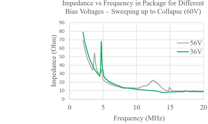
20 applications requiring a higher center frequency, the CMUT has additional bandwidth capability
from collapse mode if bias voltage is further increased. In collapse mode, the resonant frequency
increases more than 2x because the center of the membrane touches the bottom electrode and
becomes fixed, so that the vibration mode changes to a higher frequency. The figure shows the
frequency response in air at two bias voltages. Note the appearance in the 56 V data of a broad
peak at 12 MHz. This same frequency translation occurs with the fluid loaded membrane as the
peak frequency response moves from 2 MHz to 5 MHz. The collapse mode is very useful in this
work for proving the full biphasic communications concept using the commercially available
LTC6820 protocol device, which needs higher frequency and bandwidth than conventional mode
could provide. Collapse mode may not be optimal for wireless power because ultrasound
attenuation increases with frequency and transition losses in the power converter will increase.
The CMUT devices have a fundamental need for a voltage bias in order to operate as a
power receiver. Without further development of the device, the need for this voltage supply
could be in conflict with the idea of a remote device as being self-biased ready to generate 0 10 20 30 40 50 60 70 80 90
0 5 10 15 20
Impeda nc e (O hm) Frequency (MHz)
Impedance vs Frequency in Package for Different Bias Voltages – Sweeping up to Collapse (60V)
56V 36V
21 electric power upon receipt of ultrasonic energy. In this proof-of-concept, we used an external
power supply that varied from 30 V to 50 V to give conventional mode operation for the CMUT.
Future work can address this unmet need through the use of pre-charged CMUTs. The
conclusions contain a brief discussion of possible approaches for pre-charged CMUTs found in
the literature.
There are a number of ways to manufacture the CMUT using the MEMS toolkit of
surface and bulk micromachining. One of the simplest techniques is a low temperature, low step
count process employed by the IMIST group at NC State [24]. It uses a combination of bulk and
surface micromachining techniques. At the core of this fabrication process is anodic bonding of
a borosilicate glass wafer with a silicon on insulator (SOI) wafer. Anodic bonding uses elevated
temperature and voltage to cause mobile ions in the borosilicate glass to migrate into the SOI
wafer, first electrostatically bonding the two wafers, then chemically bonding them. The main
advantages of anodic bonding technology is that it employs lower temperatures that will not
destroy metallization, and it is somewhat less sensitive to the smoothness of the two wafer
surfaces when compared with fusion bonding. Prior to bonding, cavities and interconnect
channels are etched into borosilicate wafer, followed by patterning of the bottom electrode in a
metal deposition lift-off process. The resulting CMUT vacuum gap is determined by the depth
of the cavity in the glass minus the height or profile of the metal interconnect. The walls of the
cavities become insulating support posts after the next step. The completed bottom plate is then
anodically bonded to the device side of the SOI wafer, with a thin nitride layer deposited on the
silicon as a dielectric insulator and to prevent contamination of the membrane with impurities
that could outgas over time. The thin monocrystalline silicon device layer (~2 µm) on the silicon
22 handle, is mechanically polished then chemically etched back to expose the previously buried
oxide now covering the thin membrane. During the bonding, gases are released that become
trapped in the cavities and lead to their pressurization. These gases are purged by opening a vent
to the cavities in the next step, which also exposes the buried electrode and allows contact to it.
The following steps etch the (buried) oxide on the handle wafer and make electrical contact to
the membrane or top plate, finally adding a thin silicon nitride passivation layer after pulling a
vacuum on the cavity, to seal it off from atmospheric pressure and to electrically isolate the top
and bottom electrode metals. With a small increase in cost and complexity, the borosilicate glass
wafer can have predefined thru-vias allowing the CMUT to be bonded directly to its electronics
using “flip-chip” technology and saving area in small form factor applications [25]. The
possibility of heterogeneous integration is one of the key advantages of using the CMUT instead
of piezoelectric technology, besides the superior device performance. The biological
disadvantage from the rigidity of both piezoelectric and CMUT technology is partially offset by
the compactness of the CMUT technology when it is integrated with the supporting electronics.
In either implementation, off-chip passives can be connected to the electronics through schemes
metallizing (Platinum) a biocompatible flexible substrate (PDMS), followed by passivation of
23
CHAPTER 3. Ultrasonic Wireless Power 3.1 Power Converter Architecture
A key requirement of the implantable device is wireless power delivery. The stored
energy need only last as long as it takes to make the clinical measurements and transmit the data.
Multiple cycles of power delivery followed by a reasonably long measurement phase are
possible. A wireless ultrasonic power recovery scheme is demonstrated in oil using a single
element CMUT and a circuit made with commercially available devices: diodes, transistors, an
inductor and a comparator with open drain output for the boost regulator. The 2-mm diameter
CMUT element with area = 3mm2, a diode rectifier bridge and an inductor-based boost circuit form the power conversion circuit. In these experiments, the bias voltage for the CMUT is
supplied externally, but the plan is to develop a pre-charged device to eliminate the bias.
The inductor-based buck-boost circuit is selected over the capacitor-based charge-pump
voltage step-up because it does not require any mode changes (i.e., doubler, tripler, fractional) to
provide power over the wide range of output voltages encountered in charging a battery. This
buck-boost circuit typically operates in discontinuous conduction mode, which means the
inductor current starts from zero at the beginning of each cycle.
24 The operation, which is hysteretic based on the input voltage, can be briefly described as
follows. During the positive phase of the voltage at VAC, the switch MN1 turns on and the
inductor current increases, supplied to VRECT from the CMUT through the 2.2nF coupling
capacitor and diode D1. During the negative phase of VAC, the switch turns off and the inductor
discharges current to the output VBST through D5. The inductor current is supplied by D3 during
the negative phase of VAC. Also, during this phase of VAC, the charge on the CMUT and 2.2nF
coupling capacitor is replenished through diode D2. In this manner, the acoustic energy is
converted to current and this electrical energy is transferred to the output using an inductive
storage element.
3.2 Experimental Setup
On the power recovery circuit, we investigated two different sizes of CMUT elements,
variations in transducer excitation frequency, CMUT bias voltage, circuit component selection,
and active vs. passive rectifier design. During our experiments, the current supply for the boost
circuit (LMV7235, Texas Instruments, Dallas, TX, USA) was provided separately, but it could
be supplied from the boosted output or from a rectified input. The ultrasonic signal was
Boost Converter
Charge Pump 1-MHz focused
transducer
CMUT
25 provided by a 1MHz, 25mm focus, 12mm diameter, commercial piezoelectric transducer
(A303S, Olympus, Waltham, MA, USA) driven by a waveform generator (33500B, Keysight,
Santa Rosa, CA, USA) set to 10 V peak-to-peak and 50 Ohm load. The pressure field from this
transducer was measured in oil using a hydrophone + preamplifier (HGL-0200 & AH-2010,
Onda, Sunnyvale, CA, USA) to verify that the power did not exceed the 7.2 mW/mm2 ISPTA limit. The pressure was found to be relatively uniform over the 1.5 mm diameter of the CMUT at
the 23 mm range where the experiments were run. The peak-peak pressure and peak power at
the driving voltage of 10 Vp-p were measured to be 276 kPa and 6.2 mW/mm2 at a distance of
17mm from the transducer face. The main lobe width of the lateral/azimuthal pressure
distribution at 1.3MHz was consistent with the transducer geometry. Full-width half max is
computed as 2λz/D = 2*1mm*23mm/12mm = 4mm. The length of the focal area was also
consistent with theoretical depth of field. DOF= 8F2λ = 8*22*1mm. What these two results imply is the sensitivity of power recovery to mote placement (or external transmit focus) will be
much higher in the lateral dimensions than the axial (depth) dimension.
26
3.3 Key Results
The highest power achieved (1.1 mW) used the active rectifier at bias voltages
approaching CMUT collapse, and at excitation frequencies (1.2 MHz) where we find the center
frequencies of the transmitter and the CMUT match. These results were achieved using a 330 µH
inductor and “active” rectifier Q1 on the chargepump input. The initial experiments used a
Schottky diode at D1 between the VAC and VRECT nodes, but replacing this diode with a PNP
transistor improved power conversion by a factor of three, from 300 µW to 900 µW. An
additional 25% improvement to 1.1 mW was achieved by replacing the initial 470µH inductor
with a 330 µH value. A key takeaway for the future design is that minimizing voltage drops
0 300 600 900 1200
36 39 42 45 48
Out put P owe r ( m W )
CMUT Bias Voltage (V)
0 300 600 900 1200
0.8 1 1.2 1.4
O ut put P ow er (m W )
Transducer Input Frequency (MHz)
Results of ultrasonic power conversion with COT based circuit above
27 across the rectifying elements can yield large gains in power conversion. The integrated circuit
can implement active rectifiers replacing each of the diodes in this circuit as will be discussed in
28
CHAPTER 4. Ultrasonic Wireless Communications
One challenge for implementing microscale implantable ultrasonic telemetry is getting
data into and out of the remote device. To achieve robust data transmission, one needs to have
unambiguous interpretation of when data is being transmitted – that is the start and stop of the
data frame; and the bits, 1’s and 0’s should be transmitted in such a way that the data can be
sampled unambiguously in the presence of amplitude distortion and variable latency. There are
various methods for ultrasound that are compatible with continuous wave transmission, such as
frequency shift keying (switching frequency between 1’s and 0’s) and phase shift keying, which
is similar except with phase, and on/off shift keying [26]. To synchronize up, to determine which
data represents the start of the frame and how to interpret a long chain of 1’s or 0’s, there are
various digitally intensive techniques such as bit stuffing to ensure that the clock signal is
recoverable from the data stream. The technique investigated in this work eliminates the need for
all this complexity. It uses single ultrasonic pulses and inverts the phase to signal the data
polarity. To distinguish between control signals like start and stop of transmission, and the data,
two easily distinguished frequencies are employed. It also solves the problem of continuous
wave transmission which would quickly drain the device’s energy reservoir.
4.1 Wireless Uplink Considerations
Compared to the on-off shift keying techniques, the anticipated advantages of using this
single-pulse system with phase indicating polarity is 1) increased data rate, as high as 500 kHz
with data signal frequency of 3 MHz, and control signal frequency of 1 MHz, assuming the two
types of pulses can be spaced at 2 µs; 2) better immunity to multipath interference, which could
29 power efficiency because the communications can be concluded using a smaller number of
pulses, less time and thus less energy.
4.2 Approach
A key aspect of the implantable device is the transmission of data collected during
pulse-echo ranging to the external unit for diagnostic analysis and periodic monitoring. It is desirable
for translation into the clinical setting to use a common bus standard, such as serial peripheral
interface (SPI) and convert this standard to a “one-wire” differential protocol to drive the CMUT
and generate pressure waves. The pressure waves will then be received by a second CMUT,
converted to electrical signals and decoded to convert them back to the SPI signals.
Implant Data Out
Biphasic Encoding Biphasic Pressure Transduced
Data Read From Implant
30 The broadband characteristics of the CMUT are key to the use of an industry standard
“IsoSPI™” protocol we selected, which is implemented in the protocol device (LTC6820,
Analog Devices, Norwood, MA, USA) [27]. This “cable driver” communication concept uses
single biphasic pulses with phase indicating polarity; and two distinct frequencies, 10 MHz and 3
MHz are used to communicate data and frame information, respectively.
4.3 Experimental Results
The wireless communications concept is demonstrated in an oil tank with two CMUTs,
one for transmit and the other for receive. The frequency response of the CMUT (conventional
operation) was compatible only with the chip-select feature of the protocol chip. The circuit
demonstrated correct decoding of the biphasic pulse as shown in Figure 14. The experiments
revealed that for a correct decode on the receiver side, the waveform driving the transmitting
CMUT could not be a simple biphasic square pulse as generated by the commercial transceiver.
This realization is important to the future IC design. In these experiments, to get a sinusoidal
pulse at the appropriate frequency and shape on the receive CMUT, a sinusoidal pulse of a
31 transmit side, which will eventually be done by the integrated circuit, will require a pulse
shaping circuit that converts the square pulses into a triangular shape. In frequency domain, what
this pulse shaper will do is convert the input waveform from a sinc(x) to a sinc2(x) to match the more limited bandwidth of the ultrasonic device. This need is not surprising, the CMUT is much
narrower bandwidth compared with the pulse transformers used in the cable driver configuration
for which the commercial protocol chip was designed.
The frequency range of the CMUT used this experiment and operating in conventional
mode does not extend to 6 MHz, which is the minimum needed by the commercial transceiver
for data communications. Therefore, the demonstration of decoding by the commercial
transceiver was limited to the control signals at 2.5 MHz, which is within the bandwidth of the
CMUT. It is, however, possible to test both data and control signal communications in a future
demonstration using collapse mode of the CMUT. Collapse mode operation approximately
32 twice that of non-collapse mode. The adjustments to the receive conditioning hardware are easy
33
CHAPTER 5. Clinical Applications of Wireless Implantable Device 5.1 Monitoring for Endoleak in an EVAR Stent-Graft
A miniscule ultrasonically powered device integrated into the EVAR stent-graft, or
delivered transcutaneously into the aneurysm sac prior to EVAR deployment, could provide on
demand diagnostic information about the presence of endoleak. The diagnosis of endoleak
would be based on static and dynamic measurements of the aneurysm sack dimensions and of the
stent-graft inside the vessel lumen. Medical implantable devices can be incorporated into the
EVAR stent-graft as described in US Patent 6,840,956 and polled with an external unit to record
clinically useful data from ultrasonic measurements as described in US Patent 7,198,603. The
approach described in these patents, however, is one of static measurement of pressure in the
aneurysm sac, or blood oxidation level, or some other static parameter. This contribution of this
work is different in that it proposes a series of lumen diameter measurements during a cardiac
interval that can be used to infer the elastic response of the implant and/or the aneurysm sac to
pulse pressure variation. In the presence of endoleak blood pressure will be equalized on both
sides of the stent/graft and this condition should reduce the variation in distance over the cardiac
interval compared with the “no endoleak” case.
34 The primary goal of this experimental setup was to investigate the echogenicity of the
EVAR device and the likelihood of measuring a differential distance across it and potentially
across the aneurysm sac. The EVAR, immersed in oil to simulate blood, is exposed to single
biphasic ultrasound pulses of ~3 MHz emitted by a single larger CMUT element excited with
(±3V) at a range of 10 mm to 50 mm – the typical EVAR is between 20mm and 30mm in
diameter. The setup for this experiment was similar to the pitch-catch used for the data
communication, with one CMUT element serving in a transmit mode, and a second adjacent
element served as receiver for returning ultrasonic energy. Ultimately, the integrated circuit will
allow the use of a single CMUT by automatically changing mode from transmit to receive after
the biphasic pulse is generated. The received signal is passed through a single stage of
transimpedance amplifier to generate the voltage waveform portrayed in the figure.
The pulse-echo response to the EVAR stent-graft is shown in the figure. One notes that
the signal returned from the trailing side of the EVAR is appreciably smaller amplitude (1/4th )
compared with the signal from the leading edge. This is due partly to 1/R spreading of the
ultrasound since we are in the far field, but also to scattering of the signal returning from the far
EVAR edge proximal to CMUT
EVAR edge distal to CMUT
CMUT EVAR stent-graft
Oil
35 side of the graft when it encounters the proximal side. This “attenuation” can be handled with
suitable electronics in the IC – namely, a time gain amplifier. The metal stent structure is found
to be highly echogenic. Investigations into the best way to represent these data for encoding and
transmission are moving forward. Considering size, power and software/hardware flexibility, it
is desirable for an external ultrasonic unit to make the data analysis while the implanted
ultrasonic device merely measures and reports the clinical data.
5.2 Other Applications
A second possible application of a wireless ultrasonic mote is to monitor progress of
incorporation of an engineered cardiac tissue graft into a damaged or infarcted region of native
heart tissue. The device investigated by the Daniele group at NC State [14] for regeneration of
infarcted cardiac tissue is “a vascularized cardiac stem cell (CSC) patch combining stem cells
with engineered biomimetic microvessels (BMV)”. The unmet need for further advancement of
this novel device for post-MI regeneration is the capability to monitor the regeneration of the
cardiac tissue in vivo without damaging the tissue with a biopsy or sacrificing the animal. It is
proposed that regeneration of the tissue in the vicinity of the graft might be inferred in-vivo from
improvement to cardiac signal flow detected using three-lead electrocardiogram measurements
made periodically. Other measurements, such as impedance of the cardiac tissue – specifically
looking at the development of intercalated disks in the patch, could also be indicators of tissue
regeneration. A wireless implantable device that is powered by ultrasound and communicates by
ultrasound could make these measurements every few milliseconds for two to three cardiac
cycles before needing to replenish the energy storage. The Aortowatch device (project title for
implantable device monitoring development of endoleak in the EVAR) shares much of the same
36 Only the analog front-end connections are slightly different: connecting to an electrode instead
of an ultrasonic transducer. The flexible electrodes would be part of the patch itself; so, some
mechanism to connect to these would have to be devised. But it is reasonable to assume that the
same basic IC design can be used for this different application with minor modifications. These
modifications would also include the length of data to be transmitted, perhaps only 2 bytes of
10-bit data are needed. Also, it may be necessary to increase the frequency of measurement to
37
CHAPTER 6. Design and Fabrication of Integrated Circuit Implementation 6.1 Overall Design Objectives
The Wireless Ultrasonic Energy Converter, Data Logger and Transponder is intended for
micro scale implantable biomedical applications which need on-demand data logging. One
application is monitoring of endoluminal vascular aortic repair (EVAR) devices for development
of leak into the aneurysm sac. This device interfaces with a CMUT to convert ultrasonic energy
from an external unit to electrical power to charge a large value capacitor. When charging is
complete, the device uses this stored energy to drive the CMUT in transmit receive mode to
make dimensional measurements of the EVAR lumen and possibly the aneurysm sac to
determine the performance of the EVAR. It then encodes this data and transmits it to the
external unit after each measurement. To capture the dynamic element of sac dimensions in
response to the cardiac cycle, the device needs to capture up to 30 measurements per second with
each measurement taking less than 1 ms including the data uplink. For the long interval (30 ms)
in between measurements, it switches to micro-power mode to conserve power.