Transactions, SMiRT-25 Charlotte, NC, USA, August 4-9, 2019
Division III - Computation, Simulation, Visualization
USE OF THE HYBRID LAPLACE-TIME FEM-BEM COUPLING
METHOD IN NONLINEAR SSI STUDIES
Theodora Makrypidi1, Charisis T. Chatzigogos2, Nicolas Greffet3, Alex Nieto-Ferro3, Pierre-Alain Nazé4
1 Géodynamique & Structure, R&D Group, Paris, France ([email protected]) 2
Géodynamique & Structure, R&D Group, Paris, France
3 Électricité de France (EDF), Paris, France 4
CEO, Géodynamique & Structure, Paris, France
ABSTRACT
The main objective of this study is to explore the relevance and conservatism of the Hybrid Laplace-Time FEM-BEM coupling method in nonlinear soil-structure interaction (SSI) studies. This method can be used in the seismic design practice and allows for consideration of nonlinear behavior in the bounded domain with a particular emphasis on the nonlinearity that is developed along the soil-structure interface (foundation uplifting). The FEM-BEM coupling method is compared with the well-known “spring” method which is the most widely used method in the seismic design practice and entails a linear substructure approach with the earthquake loading typically introduced as a pseudo-static force field after an appropriate spectral combination of characteristic maximal modal responses. The validity range and pertinence of the FEM-BEM coupling method is examined with respect to some quantities of interest characterizing the response, such as the uplift ratio of the foundation and the floor spectra developed in representative points within the structure.
INTRODUCTION
A major challenge for the seismic design and dimensioning but also for the seismic re-evaluation (especially after the earthquake of Fukushima) of civil engineering structures, in particular industrial facilities and energy infrastructure in high seismicity regions, is to develop simple, yet accurate methods for evaluating their response, as well as their capacity to meet the performance objectives set out by the design norms.
In order to respond to this challenge, numerical simulations of increasing complexity are used for the studied physical phenomena; such methods are expected to lead to optimized seismic designs both in terms of safety and financial viability. Several recent studies (Pecker et al. 2014) have highlighted the major impact of nonlinear soil-structure interaction on the seismic response of structures. It is thus of primordial importance that novel numerical methods developed for seismic design and dimensioning are able to appropriately quantify such effects (i.e. soil plasticity, foundation uplift, sliding along foundation interfaces etc.)
In direct methods, a modelling based on conventional finite elements is used for both spatial domains exhibiting either linear or nonlinear behavior; the dynamic response is obtained through integration of dynamic equilibrium equations in time domain. The method can be implemented using finite element codes of general application provided that an appropriate method for introducing the seismic excitation and boundary conditions can be adopted.
In hybrid methods, the complete soil-structure system is decomposed into two subdomains which are independently modelled. The basic principle of hybrid methods is to consider that all nonlinear phenomena are developed in the bounded domain whilst the unbounded domain remains linear; thus, the linear unbounded domain is represented and solved using the Boundary Element Method (BEM) (different variants may be used: Thin Layer Method - Kausel 1994, Scaled Boundary Finite Element Method - Dasgupta 1982), which is more conveniently formulated in the frequency domain (real frequencies Fourier domain or complex frequencies Laplace domain), while the bounded nonlinear domain is discretized with the Finite Element Method (FEM), and solved in the time domain. As a result, a FEM-BEM coupling method subsequently arises, which in turn allows for adopting the most suitable numerical techniques for each subdomain. The implementation of hybrid methods, especially for the treatment of unbounded domains, requires the use of appropriate BEM software, such as SASSI2010 (Deng & Ostadan, 2012) and MISS3D (Clouteau, 2007).
Finally, substructure methods are used for solving the interaction problem for systems with linear or limited nonlinear behavior. The bounded domain (structure) is modelled with finite elements and the unbounded domain is discretized with boundary elements. The artificial boundary condition which is applied on the superstructure domain is usually expressed by a force-displacement relationship defined on the soil-structure interface by means of the so-called impedance operator. This motion relationship can be expressed in the frequency domain; combinations of time and frequency domain solution methods though can be also employed (Dasgupta 1982).
The present work aims at establishing a quantitative comparison between a novel hybrid FEM-BEM coupling method and the well-known linear “spring” method prescribed by the majority of existing seismic design norms (the latter belongs to the substructure methods). These two methods are used to study a simplified soil-structure configuration pertaining to a superficial industrial building with basemat, which is founded on a homogeneous soil profile; for simplicity, the only nonlinearity taken into account is foundation uplifting. The validity range of each method is examined with respect to some quantities of interest characterizing the overall dynamic response, such as the basemat uplift ratio and the floor spectra in representative points within the structure.
BASIC ASSUMPTIONS FOR THE STUDY
A study of a typical industrial building, simple enough to facilitate extrapolation of conclusions for a wider range of civil structures, is herein considered. The structure is a symmetric reinforced concrete building composed of continuous external and internal vertical walls, horizontal slabs and roof, and an interior substructure modelled as a single-degree-of-freedom oscillator, attached to the basemat. The building is founded on a mat shallow foundation, which is allowed to uplift, and lies over a homogenous soil, modelled as a linear viscoelastic half space.
building and characterized by curves for ratio / and corresponding damping ratio versus shear distortion .
Figure 1: Soil-structure configuration examined in the study
The seismic loading is represented in the horizontal direction by a design response spectrum for medium soils typically used in the nuclear industry (cf. document EUR), while the vertical component is defined as 2/3 of the horizontal one. In addition, a set of three spectrum-compatible acceleration time histories has been defined in order to establish the seismic input to be used in nonlinear analyses. For convenience, a planar seismic excitation is considered in parallel to symmetry plane (i.e. horizontal component parallel to axis is zero, cf. Figure 1).
The presented soil-structure configuration is studied for one seismic scenario, in which the horizontal spectrum is scaled at 0.25g. The calculations are performed using both the conventional “spring” method (denoted LP) and the nonlinear FEM-BEM coupling method (denoted NLT-HLT) allowing for a coupling of nonlinearities in the time domain with a BEM formulation of the soil impedance matrix in the Laplace domain.
CONVENTIONAL SPRING METHOD
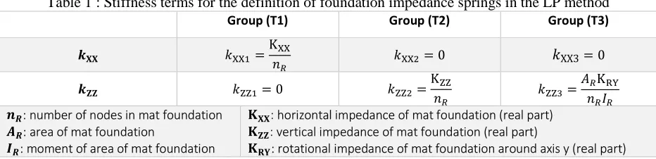
In what regards the implementation of the conventional spring method (LP method), linear behavior is postulated everywhere. Hence, following Kausel’s superposition theorem (Kausel et al. 1978), the problem is divided into the following three sub-problems: 1) the problem of kinematic interaction, 2) the calculation of dynamic impedance, and 3) the resolution of the structural problem considering the solution of the second sub-problem as boundary conditions and imposing the result of the first sub-problem as excitation. The unbounded soil domain is replaced by three groups of springs coupled with dashpots (denoted T1 to T3, cf. Figure 2) aiming at representing the dynamic impedance of the foundation. The values attributed to the vertical and horizontal stiffness of the springs in each group are given in Table 1. Similar expressions apply for the damping terms.
Table 1 : Stiffness terms for the definition of foundation impedance springs in the LP method Group (T1) Group (T2) Group (T3)
K
0 XX3 0
0 K K
!": number of nodes in mat foundation #": area of mat foundation
$": moment of area of mat foundation
% : horizontal impedance of mat foundation (real part) % : vertical impedance of mat foundation (real part)
Figure 2 : Modelling principle – linear spring method (LP)
FEM-BEM COUPLING
As an alternative to the conventional LP method, where the dependency of the foundation impedance on the frequency of excitation cannot be taken into account, hybrid method with frequency-time domain coupling (NLT-HLT) can allow for an exact determination of soil stiffness and radiation damping in the entire frequency range. For the numerical implementation, a FEM model for the bounded substructure is coupled with a BEM formulation of the soil impedance matrix that takes into consideration simultaneously both inertial and kinematic soil-structure interaction. For the applications herein presented, Code_Aster, an open-source finite element modelling code developed and maintained by EDF R&D, is used for the bounded domain. The soil impedance matrix and the equivalent seismic loading, (imposed along the soil-foundation interface under the assumption of flexible foundation) are computed with code MISS3D, a frequency-based boundary element code originally developed in Ecole Centrale Paris (Clouteau, 2007).
In this framework, the FEM-BEM coupling method is formulated via the introduction of a modal basis (a sub-structuring method of the eigen-modes with projection on a Ritz basis) where force and displacement fields are projected on. For the computation of soil-structure interaction, MISS3D needs a modal basis comprising a set of structural eigen-modes (that can be zero on the soil-structure interface) combined with non-zero modes on the same interface. For the first set of eigen-modes, we use the structural eigen-modes obtained by blocking displacements on the interface; for the second, we use the set of static eigen-modes (also known as “constrained” eigen-modes), recursively obtained by imposing a unit displacement at every degree of freedom (dof) of the nodes located on the interface (foundation).
It should be noted that the currently available computing resources (the possible number of interface nodes is restricted to 10,000 because of the direct MISS3D solver) render the modelling of the soil-structure interaction effects including the complete set of constrained static modes, extremely time consuming; this limitation raises the question of reducing the size of the discretized system (the total number of dofs) by replacing the complete set of constrained static modes with a small number of foundation eigen-modes, calculated through the use of spectral properties of the dynamic operator, condensed to the interface and selected on the basis of an appropriately established criterion, which is the so-called Balmes criterion (Balmes 1996). This purely algebraic method can be decomposed as follows:
• projection of mass and stiffness matrices on the basis of static interface modes, • calculation of the associated modes,
In the case of nonlinear behavior, the hybrid method (NLT-HLT) is employed. In this approach, all nonlinearities are confined in the bounded FEM domain that includes not only the superstructure but also a possibly nonlinear domain of surrounding soil (near-field soil domain). On the contrary, the far-field soil domain is assumed to be linear and hence, it can be resolved by means of a BEM formulation. The nonlinear problem must be formulated in the time domain, and for stability issues, it has been shown (Nieto Ferro et al. 2014, Nieto Ferro 2013) that the soil impedance matrix delivers more reliable results if it is initially computed in the Laplace domain and then it is converted into the time domain. The study of foundation uplift, a geometric nonlinearity that can be modelled in Code_Aster applying different strategies, is the only nonlinear mechanism considered in the present study.
The nonlinearity is represented in the model by joint elements with an elastoplastic behavior exhibiting Signorini-type contact conditions in the normal direction and obeying the elastoplastic Mohr Coulomb criterion in the tangential direction. This element type is characterized by four parameters: normal rigidity () 10+MPa/m, tangential rigidity (, 2 . 10+MPa/m, adhesion / 0.001MPa (which is related to the tensile strength 1, //23 and the coefficient of Coulomb friction 2 1. In addition, an isotropic parameter of work hardening ( 10+MPa/m, which regularizes the tangential slope in the phase of slip is introduced. It has to be noted that the considered joint elements are 8-noded finite elements with zero/negligible thickness (degenerate volume elements). The basemat-soil interface exhibits an infinite friction resistance (rough interface) and a negligible adhesion. All nonlinear seismic analyses are performed after gravity initialization, in which permanent and variable loads in the building are considered.
Figure 3 : Modelling principle - FEM-BEM Coupling (NLT-HLT)
RESULTS
The results of this work focus on two specific aspects of dynamic response, namely: a) maximum uplift ratio developed during loading, and b) floor response spectra in positions of interest within the building. Uplift ratio is calculated as the ratio of the area of uplifted zone over the total basemat area. In particular, for the linear method, uplift ratio is calculated based on the number of rigid links (defined along the soil-mat foundation interface) which are in tension, and for the nonlinear method, based on the joint elements that are “open” (i.e. they exhibit negligible tensile normal force and the development of a gap).
Floor response spectra are calculated in five positions in the horizontal and/or vertical direction. The positions selected for calculation of these quantities are presented on Figure 3b.
Maximal Uplift ratio
Figure 4 presents, for the LP method, the obtained cartography of the normal stresses developed on the underside of the mat foundation as well as the cartography of the anticipated uplifted zone for the most conservative seismic combination (G + EX + 0.4EZ: seismic vertical acceleration acting upwards).
Figure 4 - Pressure diagram and maximal uplift ratio – LP
Figure 5 presents, for the NLT-HLT method, the obtained cartography of the normal stresses exerted on the underside of the mat foundation as well as the cartography of the uplifted zone for the moment of the maximal uplift, which corresponds at the time of 10.955s.
Figure 5 - Pressure diagram and maximal uplift ratio – NLT-HLT
The difference between the two methods is important (maximal uplift ratio for LP 0.31 and maximal uplift ratio for NLT-HLT 0.46). In the LP method, the stress distribution below the raft is approximately linear and this is because of the introduction of soil springs with uniform stiffness. The method does not rigorously allow for an exact calculation of the uplifted zone but only for the zone in which the springs are in tension. As such, the estimation of the extent of the uplifted zone with the LP method can be considered acceptable only for slight seismic loads. In all cases, the overturning moment in the LP method is taken by a symmetric triangular diagram of tensional and compressive stresses in the springs, which implies that any uplift ratio calculated with the LP method cannot exceed 50%.
observed at the interior of the compressive zone correspond to the positions of internal walls. In the uplifted zone, normal stresses are rigorously equal to the introduced tensile strength (approximately zero). It is noticeable that within the NLT-HLT method, uplift ratios as high as 100% can be obtained (situation, which would correspond to overturning). In the current studied case, a maximal uplift ratio equal to 46% is obtained. The building starts to rock towards the end of shaking (after 10sec), with its characteristic frequency, which is around 1.5Hz (cf. Figure 6).
Floor response spectra
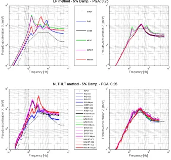
Figure 6 presents the obtained 5% damping floor response spectra for the LP method and the NLT-HLT method in both horizontal and vertical directions. It has to be noted that transferred response spectrum calculation in the LP method is performed using code FSG (Igusa and Der Kiureghian, 1995) directly based on modal characteristics of the structure.
Figure 6- Floor response spectra
As for the introduction of damping in the NLT-HLT method, the matrix of the global damping of the superstructure is calculated using the Rayleigh formulation. The definition of the parameters is based on the criterion that the critical damping between 1Hz and 10Hz is approximately equal to 7% (attributed value of damping in the superstructure). Soil damping is introduced by the macro-element which represents the exact impedance of the unbounded domain (rigidity but also radiation and hysteretic damping).
calibrated for this mode. However, for the mat foundation mode, the LP method is underdamped as radiation damping is not taken into consideration. For the mode of the internal structure, the NLT-HLT method gives a slight amplification which may be a consequence of Rayleigh damping (which is smaller than hysteretic damping within the calibration interval).
CONCLUSIONS
The paper has presented an implementation of the innovative hybrid Laplace-Time FEM-BEM coupling method for a nonlinear soil-structure interaction study. In order to assess the outcome of this implementation, a simplified method is considered and used as a reference. After discussing the basic theoretical principles for the two methods, a typical configuration of an industrial building was subjected to a moderate seismic excitation with a particular emphasis on the nonlinear mechanism of foundation uplift. Several aspects of the overall structural response have been studied, such as calculated uplift ratio and floor response spectra at several representative sections within the structural system. At this stage of the study, only the raw results have been presented so as to identify the subtleties and fully comprehend the implementation of the NLT-HLT method. To the best of our knowledge, this the first ever implementation of the NLT-HLT method for calculation of foundation uplifting in seismic studies.
Moreover, this study can be pursued by parameterizing different soil-structure configurations for varying seismic intensities and scenarios so that the outcome of the conclusions may cover a larger scope in the realm of seismic design of civil structures, as in Chatzigogos et al. (2014)
Finally, the ultimate perspective of the work consists in formulating guidelines for the design norms that identify the most adapted hierarchy of analysis methods for design cases with increasing levels of shaking and accordingly, more pronounced effects of nonlinear soil-structure interaction.
REFERENCES
Balmes E (1996). Use of generalized interfaces degrees of freedom in component mode synthesis IMAC. Chatzigogos CT, Nazé PA, Rambach JM, Billion P, Caudron M, Guisard S (2014). Uplift evaluation of
structures under seismic loading: Assessment of different calculation methods and design guidelines, Proceedings of the 2nd European Conference on Earthquake Engineering and Seismology, Istanbul, Turkey.
Code_Aster. Analyse des Structures et Thermomécanique pour les Études et les Recherches. EDF, version 12.6, http://www.code-aster.org
Dasgupta G (1982). A finite element formulation for unbounded homogenous continua, Journal of Applied Mechanics (ASME), 49(1):136-140.
Deng N, Ostadan F (2012). SASSI2010, A System for Analysis of Soil-Structure Interaction. Geotechnical Engineering Division, Civil Engineering Department, University of California at Berkeley, version 1.
EUR – European Utility Requirements for LWR nuclear power plants.
Igusa T, Der Kiureghian A (1995). FSG: Floor spectrum Generator, Last revision.
Kausel E (1994). Thin layer method: formulation in the time domain, International Journal for Numerical Methods in Engineering, 37:927-941.
Kausel E, Whitman A, Murray J, Elsabee P (1978). The Spring Method for Embedded Foundations, Nuclear Engineering and Design, Vol. No. 48.
Makrypidi T (2015). Présentation et comparaison quantitative des méthodes pour la prise en compte de l’interaction sol-structure sismique en régime linéaire et non-linéaire, Thesis, École Nationale des Ponts et Chaussées, France.
foundation uplift, Proceedings of the 16th World Conference on Earthquake Engineering, Santiago, Chile.
Clouteau D (2007). MISS3D - Manuel Scientifique & Manuel Utilisateur.
Nieto Ferro A, Clouteau D, Greffet N, Devesa G, Caudron M (2014). Nonlinear dynamic soil-structure interaction in earthquake engineering, Proceedings of the 2nd European Conference on Earthquake Engineering and Seismology, Istanbul, Turkey.
Nieto Ferro A (2013). Nonlinear dynamic soil-structure interaction in earthquake engineering, Ph.D. Thesis, Ecole Centrale de Paris, France.
Pecker A, Paolucci R, Chatzigogos CT, Correia AA, Figini R, The role of nonlinear dynamic soil-foundation interaction on the seismic response of structures, Bulletin of Earthquake Engineering, doi: 10.1007/s10518-013-9457-0.