18th International Conference on Structural Mechanics in Reactor Technology (SMiRT 18) Beijing, China, August 7-12, 2005 SMiRT18-C02-5
THREE-DIMENSIONAL MODELING OF CANDU NUCLEAR FUEL
ELEMENTS IN BOWING ANALYSIS
Shudong Yu
Department of Mechanical and Industrial Engineering
Ryerson University
350 Victoria Street, Toronto, Ontario, Canada M5B 2K3
Phone: 1 416 979 5000 ext. 7687, Fax: 416 979 5265
E-mail: [email protected]
ABSTRACT
In this paper, deformations of CANDU fuel elements under the influence of temperature gradients in pellets are investigated using the three-dimensional thermo-elastic theory and surface-surface contact theory. In obtaining a 3-D solution, all solid components are first modeled using the nine-node harmonic elements. The sub-structuring technique is then utilized to deduce a set of linear complementary equations for which a robust contact algorithm may be employed to obtain an accurate solution.
The finite element, sub-structuring and contact procedures are implemented in a computer code - FUEL3D. For testing purposes, four simple case studies were conducted in this paper using the code. The numerical results are compared with those obtained using the analytical solutions and ANSYS. Excellent agreement is achieved for all test cases.
Keywords: CANDU fuel elements, contact, finite element method, sub-structuring.
1. INTRODUCTION
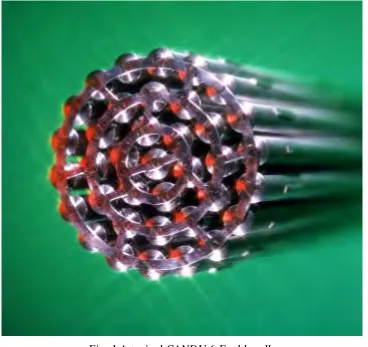
A typical CANDU6 fuel bundle consists of 37 fuel elements welded to two identical endplate, as shown in Fig. 1. The fuel elements are separated radially and circumferentially by spacer pads at several axial locations for adequate heat flow in all sub-channels. During operations, the fuel bundle rests on the inside of a pressure tube at locations of the bearing pads welded to all outer fuel elements.
A CANDU nuclear fuel element contains a thin and hollow Zircaloy sheath, a number of solid UO2 pellets and
two end-caps, illustrated in Fig. 2. Because of the horizontal placement of CANDU fuel bundles in a reactor, a fuel element may bend due to gravity, hydraulic drag, and thermal loads. In the Canadian nuclear industry, lateral bending of fuel elements is referred to as bowing, and often assessed using the BOW code (Veeder and Schankula 1974, Tayal 1989, Yu and Tayal 1995).
To achieve a good balance between the computational efficiency and accuracy, the BOW developers adopted the composite beam models. With the help of post-irradiation examination (PIE) data and two empirical coefficients (rigidity enhancement factor and curvature transfer factor), BOW has been used quite successfully for bowing analysis of fuel elements under various operating conditions. However, in order for BOW to be used in confidence for quantifications of new high burnup fuels such as the Advanced CANDU Reactor (ACR) fuel for which in-reactor measurements and PIE data are not available, it is necessary to evaluate the use of composite beam models for elastic and elasto-creep deflections.
Fig. 1 A typical CANDU 6 Fuel bundle
Midplane sheath endcap
Pellet R 1 Pellet R Np/2
Fig. 2 A schematic view of a CANDU 6 fuel element
In a CANDU 6 fuel element, the nominal radial gap between the sheath and pellets and axial radial gaps between the neighboring pellets are very small. As a result, the thermally induced deformations, e.g., bending, of individual pellets may be transferred to the sheath. The degree of transfer is dependent on many factors such as fuel element geometry, interfacial pressures, etc. Under certain conditions, the phenomenon of this curvature (bending) transfer may be modeled using the beam finite element method. Use of beam finite elements has been found efficient and reliable for assessing fuel element bowing. However, to effectively and accurately account for the amount of bowing caused by the thermally-induced bending of pellets, empirical coefficient, termed as the curvature transfer factor (CTF) and rigidity enhancement factor must be specified when running BOW. Value of the CTF cannot be determined as a priori from the BOW code itself for an application. Because of the complexity of fuel geometry and operating conditions, the coefficient may vary considerably for one application to another. In the extreme case, local pellet bending does not cause global bending of a fuel element; the beam theory cannot be used to predict the bowing of the fuel element.
sheath through contacts, and (ii) determine the conditions for which deformations fuel elements may be modeled as composite beams. To accomplish these objectives, rigorous modelling of 3-D thermo-mechanical behavior and large-scale multibody contacts is required. This paper presents the most recent attempt in the Canadian nuclear industry to resolve a key issue in dealing with modeling of bowing of CANDU fuel elements.
2. DESCRIPTION OF METHODOLOGY
In a CANDU fuel element, all components are axisymmetric in geometry. As a result, a special type of three-dimensional finite element may be used in the thermo-mechanical analysis (Hsu, 1986; Yu and Xu, 1999; Yu et al. 2004). Variation of a thermo-mechanical quantity in the circumferential direction within a finite element may be represented using the Fourier series while variation of the same variable in the radial and axial directions may be established using polynomial type shape functions. In this paper, the nine-node lagrangian element (Bathe, 1996) is used as the two-dimensional elements. The complete shape function for a finite element is the combination of polynomials and sinusoidal functions.
For each solid component in a fuel element, a set of governing equations of equilibrium may be established using the 9-node harmonic finite elements. In these equations, the contact forces on all paired contact surfaces are unknown. Through these contact forces, a set of equations for one body is coupled with other contacting bodies sets. The total number of degrees of freedom is usually very large in a three-dimensional finite element model in order to adequately discretize each component. However, only a small set of interface degrees of freedom (DOF’s) is directly responsible for coupling with other bodies. To increase the computational speed when dealing with contact problems, the governing equations for each individual component are restructured to eliminate all interior DOF’s.
Contact problems represent a special class of non-linear problems in a finite element analysis. In dealing with large scale, multibody contact problems in a CANDU nuclear fuel element, a point-to-point contact scheme and the linear complementary equations method (LCEM) in conjunction with the finite element method are found to be advantageous compared with other contact methods. They can be summarized as follows: (i) no initial guess of contact stiffness is required; (ii) existence and uniqueness of a solution are guaranteed if the contact matrix in the LCE’s satisfies the semi-positive conditions (Bazaraa and Shetty, 1979, Sha et al. 1996); and (iii) contact conditions are simultaneously satisfied at all contact nodes. The only disadvantage perhaps is the intensive matrix manipulations required in sub-structuring.
3. FINITE ELEMENT FORMULATIONS
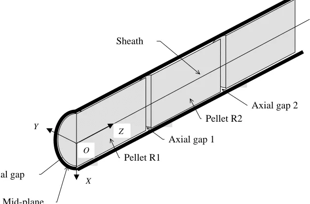
Because of small nominal gaps everywhere within a CANDU fuel element, as illustrated in Fig. 3, all components in a fuel element may be assumed to experience small deformations. The linear thermo-elasticity theory can be used to relate the stresses and strains within each component. Effects of frictions are considered small and negligible.
For an axisymmetric solid (pellet, sheath or end cap) in a fuel element, it is convenient to formulate the equations of equilibrium using the cylindrical coordinates, r, θ and z. The equilibrium equations of a material point in a solid may be formulated in the cylindrical coordinates using the thermo-elastic stress-strain relations for a linearly elastic material (Boley and Weiner 1960). In the nuclear fuel, the thermal strain components are commonly defined using the following integrals because of the large temperature gradient and variation of thermal coefficients with temperature (ISNC 1999)
{ }
T TT z T
T T
T r th
dt dt
dt
=
∫
∫
∫
0 0 00 0
0
α α
α
ε θ (1)
where αr, αθ and αz are the linear thermal expansion coefficients in the radial, circumferential and axial
directions, respectively, which are dependent on temperature and other parameters; T is the final temperature; is the reference temperature; t is the temperature integration variable.
0
T
From the minimum potential energy principle (Bathe 1996), the following equilibrium equations may be obtained
[ ]
K{ } { } { } { }
U = Q + F + P (2) where{ }
U is the nodal displacement vector of an axisymmetric component;[ ]
K is the component stiffness matrix; is the ordinary load vector (due to known thermal loads, body forces, and surface loads); is the constraining force vector;{
Q}
{ }
F{ }
P is the contact force vector.employed. Since the displacement variations in the circumferential direction are sinusoidal, they are not ideal for handling point-to-point contact. To overcome this drawback while maintaining the displacement field introduced according to the axisymmetry, the displacements of material points in the direction normal to a potential contact surface are related to the harmonic variables through a simple transformation established for evenly spaced circumferential grids (Yu et al. 2004). The nodal displacements at these pre-determined locations are then used in the contact formulation.
Y Z Pellet R1 Pellet R2 O Mid-plane
Axial gap 1
Axial gap 2
ial gap
Sheath
X
Fig. 3 A sectional view of a fuel element
4. COMPONENT EQUATIONS
To obtain a solution that satisfies the equilibrium equations, ordinary boundary conditions and contact conditions simultaneously, the original equilibrium equations for all component equations, similar in form to Eq. (2), are restructured so that the interior DOF’s are expressed in terms of the interfacial DOF’s. This section prepares the formulation of LCE’s containing only interfacial DOF’s.
4.1 Sheath
The sheath is a thin and slender hollow Zircaloy tube. During operation, the sheath is designed to collapse onto the pellets under external coolant pressure to achieve the maximum heat transfer across the radial gap. When individual pellets bend due to non-uniform temperature distribution, the sheath bends as a result of radial pellet-sheath contact, axial pellet-pellet and pellet-endcap contact. Each sheath component surrounding a pellet is meshed in such a way that the radial contact pairs are normal to the contacting surfaces. Three finite element nodes are arranged in its thickness direction. The equations of equilibrium for each portion covering a pellet length and the axial gap on either side are first be written in terms of interior and contact nodal displacements. For a typical portion of sheath numbered “i”, i =1, 2, …, Np, the restructured equations are written as
i s r i s R s L i s R s L s r i s R s L s r i s RR s RL s Rr s LR s LL s Lr s rR s rL s rr P F F Q Q Q u u u K K K K K K K K K + + = 0 0 0 (3)
where superscript s indicates the sheath; Np is one half of the pellets contained in a fuel element;
{ }
i s ru is the
r-DOF vector, representing the radial d spl cements of nodes on the inner surface that are responsible for radial contact with the corresponding pellet;
i a
{ }
i s Lu is the L-DOF vector, representing all displacements of nodes on the left interface that are responsible for continuity between modules i−1 and ; i
{ }
uRs i is the R-DOF vector, representing displacements of n des on the right interface that are responsible for continuity between modules and ;o i
1
+
i
{ }
Qrs i,{ }
QLs i and{ }
i s RQ are the modified ordinary load and thermal load vector as ociated with r,
L- and R-DOF vectors;
s s
-{ }
is r
F ,
{ }
FLs i and{ }
i s RF are the constraining force vectors;
{ }
Prs i,{ }
i s Lare contact force vectors.
The endcaps, which joins the sheath and the endplates, play a significant role in transferring loads between fuel elements and the endplates. When pellets expand, contacts occur between the two extreme pellets and the endcaps. For the endcap on the right end, only the degrees of freedom concerning continuity with the right-most pellet are considered interfacial variables and included in the restructured equations. The restructured equations for the right endcap are written as
+ + = c P c S c P c S c P c S c PP c PS c SP c SS P F Q Q u u K K K K 0 0 c (4)
where superscript c refers to the end cap; the S-DOF vector, , is the displacements of nodes on the inside surface, responsible for continuity between the sheath and the cap; the P-DOF vector,
S
u
{ }
c Pu is the axial displacements of nodes on the inside surface, responsible for axial contact with the right-most;
{ }
FSc is the forcevector representing the interactions between the sheath and the end cap at the interface; is the contact force vector resulting from the axial contact between t e right-most pellet and the end cap;
c P P
h QSc and
c P
Q are the ordinary force vectors associated with vectors
{ }
ucS and{ }
c P
u , respectively.
4.2 Subassembly of Sheath and Endcap Equations
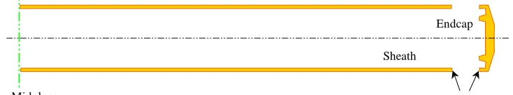
Before restructuring equations of equilibrium for pellets, it is desirable to form a sheath-endcap subassembly, as illustrated in Fig. 4, by forming equations of equilibrium for the entire sheath and joining the endcaps and the sheath at the interfaces.
Midplane
Endcap
Joining surfaces Sheath
Fig. 4 A sheath-cap subassembly
Since the two end caps are welded to the sheath along the entire circumference, the displacement continuity and force balance across the interface may be enforced to complete the equations of equilibrium for the subassembly. The twice-restructured equations of equilibrium for the radial displacements in the sheath-cap subassembly are written as
1 2
2 1
1u K u Q P
K + = rsc+
sc r sc
r (5)
where Krsc1, sc r2
K , Qrsc
u
are modified stiffness matrices and ordinary load vector; is the force vector associated with radial contact between the sheath and pellets; is the vector of radial displacements of nodes on the sheath inner surface; is the vector of axial displacements of nodes on pellet left end surfaces and end cap inner surface. 1 P 1 u 2 4.3 Pellets
For pellet i, the restructured equations of equilibrium containing one set of radial and two sets of axial contact displacement vectors are written as
i p R p L p r i p R p L p r i p R p L p r i p RR p RL p Rr p LR p LL p Lr p rR p rL p rr P P P Q Q Q u u u K K K K K K K K K + = (6)
{ }
p{ }
p p}
where superscript p indicates “pellet”; ur i, uL i and
{
i are the nodal displacements responsiblefor radial contact with the sheath, axial contact on the left interface with pellet , and axial contact on the right interface with pellet , respectively. In CANDU fuel design, pellets in a fuel element are identical in geometry and material. If the temperature distribution is identical in pellets, the stiffness matrices and thermal load vectors for all pellets are also identical. This means that the stiffness matrices and thermal load for pellets may be determined by computing the stiffness matrix and thermal load vector for a ingle pellet, which speeds up the determination of component equations.
]
5. LINEAR COMPLEMENTARY EQUATIONS
The equations of equilibrium for a fuel element in terms of interfacial displacements, which are responsible for radial contact between the sheath, axial contact between neighboring pellets, and axial contact between the end pellets and the endcaps, may be written as
[ ]
{ }
− − + = 2 1 2 1 1 2 1 1 P P P P Q u u u u K p R p r (7)where is the restructured stiffness matrix for all pellets and parts of endcaps; is the restructured ordinary load vector; is the vector of radial displacements of nodes on the outer surfaces of all pellets; is the vector of axial displacements of nodes on the right-end surfaces of all pellets; the vector of axial contact forces acting on the right-end surfaces of all pellets.
[
K1{ }
Q1p r
u uRp
2
P
Equation (7) is a set of equilibrium equations for all solids in a fuel element, expressed in terms of the contact displacement and contact force vectors whose size is only a small portion of the sum of the DOF’s for all individual components. These equations of significantly reduced size may be solved efficiently and reliably using Lemeke’s algorithm when they are transformed into a set of standard LCE’s with the help of the introduction of gap vectors.
To complete the derivation of the linear complimentary equations for handling contacts among a system of solids in a fuel element, andu , are designated as the reference displacement vectors. With the help of radial and axial gap vectors, the complete interfacial displacements, directly responsible for contact formulations, may be written as: 1 u 2 + − − = 0 , 2 0 , 1 2 1 2 1 2 1 g g 0 0 g g u u I 0 I 0 0 I 0 I 0 0 I 0 0 0 0 I u u u u p R p r (8)
where g1 and g2 are global radial and axial gap vectors, respectively; g1,0 and g2,0 are the initial radial and axial gap vectors; I is the identify matrix. It is noted that (i) the radial and axial gap vectors in Eq. (8) are always semi-definite positive when excluding penetration of one body inside the other, and (ii) the corresponding radial and axial contact force vector are also semi-definite positive. More importantly, the gap vectors and the contact force vectors satisfy the complementary conditions.
For convenience, the gap and contact force vectors are grouped together to form a single global gap vector and a single contact force vector as follows
= = 2 1 2 1 , g g g (9)
Introducing the variable transformations Eq. (8) into Eq. (7) by incorporating Eq. (9), the following equations are obtained
Q Mg
P− =
0 ,
0 ,
0 ≥ =
≥ T
Pg g
P (10)
whereQis the modified ordinary load vector. It can be shown that matrix M is a positive semi-definite matrix. Equation (10) is a set of standard LCE’s often studied in nonlinear programming. Bazaraa and Shetty (1979) have shown that if matrix M is co-positive-plus, Lemeke’s pivoting algorithm will produce a solution in a finite number of steps. Sha et al. (1990) proved that if matrix M is positive semi-definite, then matrix M is co-positive-plus. Therefore, if matrix M in Eq. (10) is positive semi-definite, a unique solution to the multiple body contact problem exists and can be found using Lemeke’s algorithm.
6. NUMERICAL RESULTS
A computer code, FUEL3D, was written in Fortran to facilitate the analysis of thermo-elastic deformations of components in a CANDU fuel element. The code handles the component meshing, matrix restructuring at various levels, formulating ordinary loads, solving the LCE’s, and non-graphical post-processing. Applications have shown that FUEL3D is fast, accurate, and reliable for applications directed at CANDU 6 fuel elements.
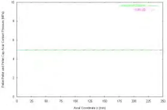
considered uniform and 50°C above the room temperature. The temperature in sheath is held at the room temperature. An initial radial gap of 40 µm is used. Because of the large initial radial gap is present between the pellets and the sheath, there is no radial contact anywhere in the fuel element. An initial axial gap of zero is used every in the fuel element. This is essentially a one-dimensional axial contact problem, for which an exact analytical solution may be obtained. Of interest here is the axial contact pressure between pellets, which may be determined using the thermo-elasticity theory and the equilibrium condition of the end cap as follows
(
)
+ − =
s s
p p p p p z
A E
A E
T T E p
1
0 0 ,
α
(11)
where αp is the linear thermal expansion coefficient (=9.25×10⁻⁶); ∆Tp is the temperature rise in pellets with reference to the room temperature (= 50°C); Es is Young’s modulus of Zircaloy (= 84.1 Gpa); Ep Young’s modulus of UO2 (= 170 Gpa); As is the cross sectional area of the sheath; Apis the cross sectional area of the pellet. Fig. 6 shows that the FUEL3D results are in excellent agreement with the analytical solution.
Fixed node Fixed node
1 2 ••• 1 16 ••• 29 30
Fig. 5 A pinned-pinned CANDU fuel element
The second set of numerical results was obtained for a two-dimensional thermo-mechanical problem in the r-θ plane of the same fuel element shown in
Fig. 5
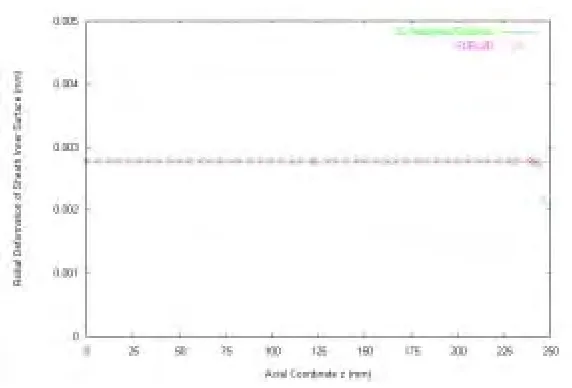
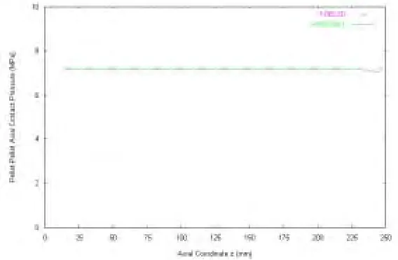
. The temperature in pellets rises uniformly to Tp,o from the room temperature while the temperature in the sheath is held at the room temperature. In this case, sufficient initial axial gap (= 0.5 mm) is present so that there are no axial contacts anywhere in the fuel element. The initial radial gap between pellets and the sheath, gr,o, is everywhere zero. In this case, the radial contact pressure away from the end cap regions may be calculated using the elasticity theory (Gere and Timoshenko, 1997). Xu (2000) obtained the analytical solutions for the uniform radial contact pressure, pr, and the radial displacement of pellets at the outer surface. Numerical results plotted in Fig. 7 and Fig. 8 for a sheath temperature of 20°C, pellet temperature of 70°C, indicate excellent agreement between the analytical solution and the FUEL3D solution everywhere along the fuel element except the region near the end cap where FUEL3D predicts higher contact pressure because of the strengthening effect of the end cap.Fig. 7 Radial contact pressure in a 2-D case
Fig. 8 Radial deformation of sheath inner surface in a 2-D case
The third set of results of numerical results was obtained for a three-dimensional thermo-mechanical problem in a fuel element. In this case, both the initial radial and axial gaps are set to zero everywhere so that contact occurs everywhere in the fuel element The temperature in pellets rises uniformly to 70°C from the room temperature while the temperature in the sheath is held at the room temperature. An independent solution was sought using ANSYS 6.1. Values of the radial contact pressure and the axial contact pressure, obtained using FUEL3D and ANSYS and shown in Fig. 9 and Fig. 10, are in excellent agreement everywhere except at regions near the end cap where some differences are observed.
The forth set of results was obtained for bending of a fuel element caused by non-uniform temperature in pellets. The following temperatures in the sheath and pellets are used
θ
cos 2
, , r
r T T T T T
p p o p p o s
∆ + =
= (12)
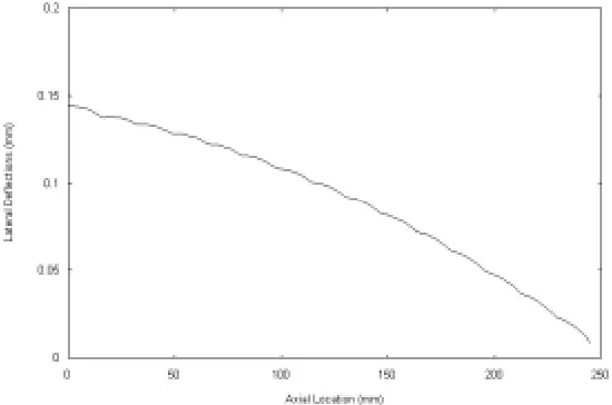
much less overall bending of the whole fuel element compared to the full contact situation. Instead significant local bending of the sheath is observed, as shown in Fig. 12. In this situation, the fuel element bending cannot be modeled using the beam theory.
Fig. 9 Radial contact pressure between sheath and pellets in a 3-D case
Fig. 11 Lateral deflection of sheath inner surface in a bending case (full contact)
Fig. 12 Lateral deflection of sheath inner surface in a bending case (partial contact)
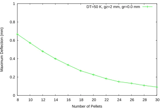
0 0.2 0.4 0.6 0.8 1
8 10 12 14 16 18 20 22 24 26 28 30
Maximum Deflection (mm)
Number of Pellets
DT=50 K, gz=2 mm, gr=0.0 mm
Fig. 13 Maximum lateral deflection of fuel element vs. number of pellets
7. CONCLUSIONS
This paper presents a combination of methods for handling three-dimensional thermo-mechanical and multi-body contact problems in CANDU nuclear fuel elements. FUEL3D, a computer code written by the author, has been used for AECL in assessing the curvature transfer phenomenon associated with the circumferential temperature variations in pellets. FUEL3D, free from use of any empirical coefficients, gives an accurate and converged solution for a large-scale multibody contact problem. Typical applications for CANDU 6 fuel elements indicate that the code is fast and reliable. Test results have also shown that the FUEL3D simulation results are in excellent agreement with those obtained using other methods.
From one of the test cases, it is found whether a fuel element can be modeled as a monolithic composite beam for lateral deflections is dependent on the degree of axial contact between neighboring pellets, radial contact between the sheath and the pellets. A CANDU fuel element contains many short, dished, and chamfered pellets stuffed inside a thin hollow sheath. As a result, bending analysis of fuel elements is very complicated due to contacts among multiple bodies. For small initial gaps everywhere within a fuel element, the collapsible sheath design, and significant hydraulic drag at all times, the composite beam model is valid during most part of the fuel reactor life. However, near the end of life, especially for high burnup fuel, the high internal gas pressure may lessen the degree of radial contact between the sheath and the pellets. In this case, the composite beam theory may not be valid.
7. ACKNOWLEDGEMENT
The author wishes to thank S. Xu, Z. Xu, K.-S. Sim and M. Tayal of Atomic Energy of Canada Limited (AECL), Canada, for their valuable suggestions and constructive criticism. Funding from AECL and NSERC (Natural Sciences and Engineering Research Council of Canada) is gratefully acknowledged.
REFERENCES
Bathe, K.J., (1996), “Finite Element Procedures. Prentice Hall”, Upper Saddle River, NJ.
Bazaraa, M. S., and Shetty, C.M., (1979), “Nonlinear Programming Theory and Algorithms”, Wiley.
Boley, B. A., Weiner, J. H., (1960), “Theory of Thermal Stresses”, Dover, Mineola, NY.
Hsu, T. R., (1986), “The Finite Element Methods in Thermomechanics”, Allen & Unwin, Boston, MA.
Sha, D., Tamma, K. K, and Li, M., (1996), International Journal Numerical Methods in Engineering, Vol. 39, pp. 721-739.
Tayal, M., (1989), Nuclear Engineering and Design, Vol. 116, pp. 149-159.
Veeder, J., and Schankula, M.H., Nuclear Engineering and Design, Vol.29, pp. 164-179.
Xu S., (2000), “Three Dimensional Thermal Stresses and Contact Problems in a CANDU Fuel Element”, M. A. Sc. Thesis, The University of Western Ontario, London, Ontario.
Yu, S. D., and Tayal, M., (1995), Proceedings of the 4th International Conference on CANDU Fuel, Pembroke, Ontario.
Yu, S. D., and Xu, S., (1999), Proceedings of the 6th International Conference on CANDU Fuel, Niagara Falls, Ontario, Canada, Vol.1, pp. 492-502.