International Journal of Emerging Technology and Advanced Engineering
Website: www.ijetae.com (ISSN 2250-2459,ISO 9001:2008 Certified Journal, Volume 4, Issue 10, October 2014)
260
Harmonic Compensation of Multiple Non-Linear Loads by
Using Phase Locked Loop Techniques
Smita Singhai
1, Prof. Dr. S. Gupta
2Department of Electrical Engineering, National Institute of Technology, Raipur, C.G., India
Abstract—In this paper, three phase shunt active power filter is used for harmonic compensation of multiple non- linear loads by using phase locked loop techniques. The circuit model consists of a standard shunt APF with IGBT inverter. PLL is capable of generating a sinusoidal output. The APF uses a PLL to generate a reference sinusoidal source current which is in-phase with load current and has the same RMS gain as the load current. A dynamic hysteresis band PWM controller is used for Current control. Within a hysteresis band the shunt line current tracks the reference current. The command signals for the inverter semiconductor switches can be produced by comparing the reference currents calculated by the controller with the measured values of compensation currents.
Keywords— Shunt Active power filter (APF), IGBT inverter, Series Inductor, Phase locked loop (PLL), Hysteresis Switching (HS), Point of common coupling (PCC).
I. INTRODUCTION
Most of the industrial load posses non-linear characteristics, examples are Uncontrolled and Controlled rectifiers, welding equipment, switched mode power supply, arc furnaces, motor drive applications etc. Nonlinear loads cause distortion in voltage and current waveforms in the ac power network. It results in harmonic, reactive power and resonance problems, higher transformer and line losses, over-voltages, over- heating, Electro Magnetic Interference (EMI) problems, and other undesirable effects. All these effects result in reducing system stability [1]-[3].
Traditionally Passive filters alone have been used to eliminate the harmonics due to their low cost and high efficiency. However, these filters have multiple drawbacks including that they generate fixed quantity of reactive power affecting sometimes the voltage regulation at the PCC at fundamental frequency. Active Power Filters (APF) or Active Power Line conditioners (APLC) are recently used for solving these power quality problems in power electronics equipments. The APF has ability to compensate all the harmonics and reactive power and after compensation keeps the system balanced irrespective of the load; i.e., nonlinear and/or balanced and unbalanced [4].
The most significant part of the APF is the controller. Conventional Proportional Integral (PI) and Proportional Integral Differential (PID) controllers have been used to estimate the reference current and control the dc-bus capacitor voltage of the inverter. However, these controllers requires precise linear mathematical model of the system, which is very difficult to obtain under load disturbances and parameter variations [5-6].
This paper proposes a APF which uses Phase locked Loop (PLL) to generate a reference sinusoidal current. The reference current is generated by the IGBT Bridge Inverter through hysteresis switching (HS).
A PLL is feedback system that fixes relation between output phase and input phase. Actually phase of both input signal and output signal are synchronized or locked, that’s why the name called “Phase Locked Loop”. The hysteresis switching current control technique has been the most suitable technique for all the applications of controlled voltage source inverters in the active power filters. The hysteresis band current control having property of good stability, high speed response, and valid accuracy [7-8]. The proposed shunt active power filter is validated and investigated under multiple nonlinear load conditions.
II. PROPOSED CONTROL STRATEGIES
Proposed methodology uses PLL controlled shunt APF to reduce the harmonic and unbalance problems from multiple non-linear loads. The shunt APF with IGBT inverter installed at the Point of Common Coupling (PCC). The three-phase shunt active power filter is a three-phase current controlled “voltage-source inverter” with a mid-point earthed, split capacitor in the dc bus [9].
International Journal of Emerging Technology and Advanced Engineering
Website: www.ijetae.com (ISSN 2250-2459,ISO 9001:2008 Certified Journal, Volume 4, Issue 10, October 2014)
261
It consists of two diode rectifiers which are phase-shifted by 30 degrees. For obtaining 30 degree phase shift between two loads, the first one is connected in Delta- Delta form and second one in Delta-Star form. The Delta-star connected uncontrolled rectifier is connected after 10 cycles to change the load output from 6-pulse to 12-pulse.The Active harmonic filter uses a PLL to generate harmonic free output current which is in-phase and has the same RMS gain as the reference current. The current error between the load current and the reference current is generated by the IGBT Bridge through hysteresis switching.
III. PLL(PHASE LOCKED LOOP)& HS(HYSTERESIS
SWITCHING)
A) PLL Introduction:
Various methods of synchronization techniques are presents. They are classified as open-loop and closed- loop techniques. Open-loop technique directly estimates the phase angle of the voltage and current signal. In closed-loop methods, the estimation of the phase is adaptively updated through a loop mechanism. This loop is aimed at locking the estimated value of the phase angle to its actual value. Therefore PLL is Negative feedback control system where fout tracks fin and rising edges of input clock align to rising edges of output clock.
Mathematical equation of frequency
( ) ( ( ))
When phase-Locked,
fout =N fin
B) Proposed PLL:
Proposed methodology uses PLL for estimation of reference current.
The load current, input frequency and terminal voltage are the input to the PLL. The distorted three phase supply voltages are sensed and given to the PLL which generates sine terms. The supply voltage is multiplied with a suitable gain before being given as an input to the PLL. Have take K=1…N, be the gain value.
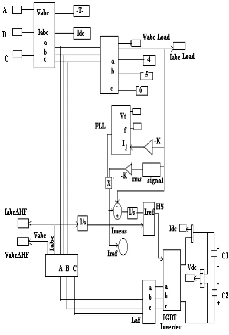
Figure 2. Simulation Model of Shunt Power Active Filter with Phase Locked Loop (PL & Hysteresis Switching (HS)
Here Il is the load current, the load voltage is Vt, the Output signal ω of the adaptive detecting circuit; and f is the fundamental reference frequency which is in phase with ac source voltage. Since the input sinusoidal reference signal, that is the fundamental component of the system voltage has the same frequency and in phase with the desired fundamental components of load current and load voltage, the dc component of the integrator output will tune accordingly until they are equal in magnitude. The corresponding fundamental real components of the voltage and current are then extracted from the sampled load current and load voltage.
( ) ( ) ( )
( ) ( )
Where
( ) ( )
( ) * ( ) ( ))
[image:2.595.313.543.135.471.2]International Journal of Emerging Technology and Advanced Engineering
Website: www.ijetae.com (ISSN 2250-2459,ISO 9001:2008 Certified Journal, Volume 4, Issue 10, October 2014)
262
Where( ) ( )
And
IL=IP+IQ+IH
VL=VP+VQ+VH
Where IP is the fundamental active component load
current; IQ is the fundamental reactive component of load
current; IH is the harmonic components in load current;
VPis the fundamental active component of load voltage;
VQ is the fundamental reactive component of load
voltage; and VH is the harmonic components in load
voltage. K1 is the proportional coefficient and K0 is the dc
component of the integrator output.
( )
( )
( )
C) Introduction of Hysteresis Switching:
[image:3.595.326.544.145.335.2]Current control is implemented through feedback modulation of a dynamic hysteresis band PWM controller. Within a hysteresis band, the shunt line current tracks the reference current. The command signals for the inverter semiconductor switches can be produced by comparing the reference currents calculated by the controller with the measured values of compensation currents. Figure 3 illustrates the principle of the dynamic hysteresis current controller technique. If the shunt line current exceeds the maximum limit of the hysteresis band, the upper half switch of the inverter arm is turned off and the lower half switch is turned on. As a result, the current starts to decay. If the current crosses the minimum limit of the hysteresis band, the lower switch of the inverter arm is turned off and the upper switch is turned on. The result is that, the current gets back into the hysteresis band. Hence, the shunt line current is forced to track the reference current with the hysteresis band.
Figure 3: Hysteresis band PWM control
D) Proposed Control Scheme:
IGBT Inverter block diagram with PLL and HS is implemented in simulink. Where the sensitive load currents are “I load”. “Imeas” the measured load currents are fed in to adaptive controller. The fundamental sinusoidal signals are obtained through the PLL using adaptive filters which all very well explained in figure 2. Let the load current Il, and the current of active filter be
the input to the shunt firing unit. The gate signal obtained from this unit is the input to the IGBT. Thus obtaining gate signal by means of hysteresis current controlling technique is performed. The gate signal “Ig” is obtained by means of using hysteresis current controlling technique. For detecting the current to be compensated, reference current should be obtained. The RMS value of load current is used for improving the PLL value. Root mean square value (RMS) of load active current can be obtained by-
International Journal of Emerging Technology and Advanced Engineering
Website: www.ijetae.com (ISSN 2250-2459,ISO 9001:2008 Certified Journal, Volume 4, Issue 10, October 2014)
263
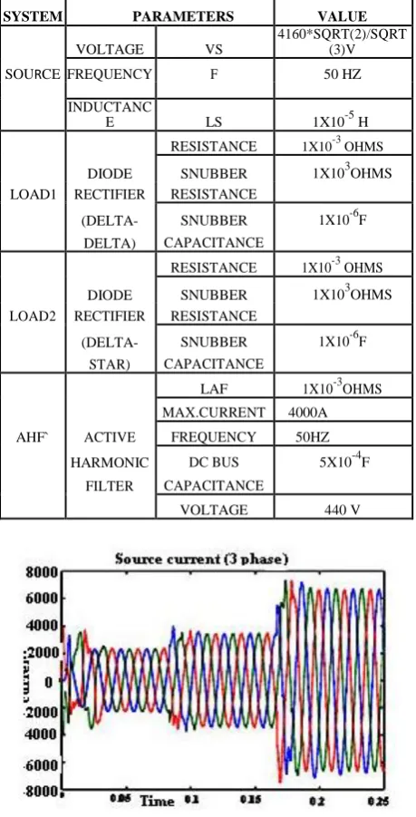
IV. SIMULATION RESULTS [image:4.595.323.536.144.284.2]Simulation is carried out on a Matlab /Simulink software. Figure 2 represents the simulation model. Harmonics which are generated by non-linear loads is removed by PLL based Shunt Active Power Filter. Given model not only considers the harmonics due to non-linear load but it also considers the disturbance presents in supply system. Figure 6.1 represents the input current wave shape, is non-sinusoidal which represents unbalanced supply. For given model, the Simulation time is 0.25 seconds. Figure 6 shows the Simulation Results. Table 1 shows simulation parameters.
Table I System Parameters
SYSTEM PARAMETERS VALUE
VOLTAGE VS
4160*SQRT(2)/SQRT (3)V
SOURCE FREQUENCY F 50 HZ
INDUCTANC
E LS 1X10⁻⁵ H
RESISTANCE 1X10⁻³ OHMS
DIODE SNUBBER 1X10³OHMS LOAD1 RECTIFIER RESISTANCE
(DELTA- SNUBBER 1X10⁻⁶F
DELTA) CAPACITANCE
RESISTANCE 1X10⁻³ OHMS
DIODE SNUBBER 1X10³OHMS LOAD2 RECTIFIER RESISTANCE
(DELTA- SNUBBER 1X10⁻⁶F STAR) CAPACITANCE
LAF 1X10⁻³OHMS
MAX.CURRENT 4000A
AHF` ACTIVE FREQUENCY 50HZ
HARMONIC DC BUS 5X10⁻⁴F
FILTER CAPACITANCE
VOLTAGE 440 V
[image:4.595.50.280.309.760.2]Figure 6.1 3 phase source current waveform
[image:4.595.322.536.316.458.2]Figure 6.2 3 phase injected current waveform
Figure 6.3 3 phase load current waveform
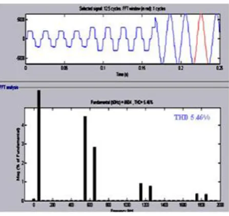
V. FFTANALYSIS
The Fast Fourier Transform (FFT) is used to measures the order of harmonics with the fundamental frequency at 50 Hz of the source current and THD (total harmonic distortion) present in selected signal. The FFT analysis of the system with and without the use of Shunt Active Filter is shown in Figure 7. The figure 7.1(a) shows the Non-linear loads directly connected with supply that means without the use of Active Filter. In that case supply current having a THD of about 5.46% which is shown in figure 7.1(b). When Active Filter is used, the THD is reduced up to about 1.52% which is shown in figure 7.2(a) and 7.2(b).
[image:4.595.327.525.643.753.2]International Journal of Emerging Technology and Advanced Engineering
Website: www.ijetae.com (ISSN 2250-2459,ISO 9001:2008 Certified Journal, Volume 4, Issue 10, October 2014)
264
Figure 7.1(a) FFT waveform of Non-Linear loads without AHF (THD 5.46%) with fundamental freq 50 Hz
VI. CONCLUSION
This projet proposes the implementation of a three-phase active power filter with three-phase locked loop. Simulation result shows, this system provides unity power factor operation of non-linear loads with harmonic current sources, harmonic voltage sources, reactive, and unbalanced components which reduces the harmonics from 5.46% to 1.52%.
Figure 7.2(a) Non-Linear loads with AHF
Figure 7.2(b) FFT waveform of Non- Linear loads with AHF (THD 1.52%) with fundamental freq 50 Hz
REFERENCES
[1] Hirofumi Akagi, Fellow, IEEE, and Ryota Kondo, “ A ransformerless Hybrid Active Filter Using a Three-Level Pulsewidth Modulation (PWM) Converter for a Medium- Voltage Motor Drive” IEEE TRANSACTIONS ON POWER ELECTRONICS, VOL. 25, NO. 6, JUNE 2010
[2] ZHENG Jiakun, MENG Chao, LI Po, HONG Yongqiang, “The Study of Transformerless Shunt Hybrid Active Power Filter Compensation for Unbalanced Load” 2012 IEEE 7th International Power Electronics and Motion Control Conference - ECCE Asia June 2-5, 2012, Harbin, China.
[3] Ab. Hamadi, S. Rahmani, Member IEEE, and K. Al-Haddad, Fellow member IEEE “A Novel Hybrid Series Active Filter for Power”, pp 1100-1104 , 2005
[4] M.asadi, A.Jalilian, H.F.Farahani, “Compensation of unbalanced non linear load and neutral current using stationary reference frame in shunt active filters” , 2010 IEEE.
[5] Jeeva S. Pridaaa1, P Tamizharasi2 and J. Baskaran3, “Implementation of Synchronous Reference Frame Strategy based Shunt Active Filter” IEEE 2011
[6] Prof.Lathika, B.S Ms.Sreedevi.G. Dr.S.Rama Iyer, “HYBRID POWER FILTER” 2008 Australasian Universities Power Engineering Conference (AUPEC'08)
[image:5.595.314.540.134.342.2] [image:5.595.53.277.137.347.2] [image:5.595.61.264.493.621.2]International Journal of Emerging Technology and Advanced Engineering
Website: www.ijetae.com (ISSN 2250-2459,ISO 9001:2008 Certified Journal, Volume 4, Issue 10, October 2014)
265
[8] Om Nayak, Surya Santoso, and Paul Buchanan. Power electronics spark new simulation challenges. IEEE omputer Applications in Power, 15(4):37-44, October 2002 converter” International Journal of Applied Engineering Reseach,DINDIGUL Vol 1,No 4, 2011.
[9] JenoPaul P, Ruban Deva Prakash T, Jacob Raglend Electrical & Electronics Engineering Nooral Islam University, Tamilnadu, “Adaptive PLL controller based shunt Active Filter for power quality improvement in Matrix converter” International Journal of Applied Engineering Reseach,DINDIGUL Vol 1,No 4, 2011.