International Journal of Emerging Technology and Advanced Engineering
Website: www.ijetae.com (ISSN 2250-2459, UGC Approved List of Recommended Journal, Volume 8, Issue 4, April 2018)256
Effect of Residual Stresses on the Strength of Material of Pipe
Due to Welding Operation
Pratap S. Kamble
1, Prof. Dr. S. G. Taji
2, Prof. A. B, Verma
31PG Student, 2Professor and Head, GP Ahmednagar, India 3
Asst. Professor SRCOE, SPPU Pune, India
Abstract: Residual stresses are pre-stresses which are present in the engineering components even when there is no external load and these develop primarily due to non-uniform volumetric change in metallic component irrespective of processes like machining, mechanical deformation, casting, welding, heat treatment, coating etc. Residual stresses may be compressive or tensile based up on the location and type of non-uniform volumetric change taking place due to differential heating and cooling like in welding. Residual stresses in the welded joints are developed due to differential weld thermal cycle heating, peak temperature and cooling at the any moment during welding experienced by the weld metal and region closed to fusion boundary.
Residual stresses cause an impact on the strength and hardness properties of the material. In this work we will study and evaluate impact of residual stresses generated in butt joint in pipe at various welding parameters. This study focuses on theoretical calculations of residual stresses and their impact using CAE module majorly ANSYS. The 03 dimensional modeling is done using modeling software. The thermo-mechanical simulation is also carried out and shows the normal, transverse and longitudinal stresses are compressive but von-Mises stresses are tensile in nature and are maximum at weld zone.
Keywords –Thermo Mechanical simulation, Residual Stresses, Ansys, MIG Welding.
I. INTRODUCTION
Types of pipe joints are major components of piping industry provided to connect multiple pipes. Pipe joint provided must withstand pressure of each pipe. There are different ways to join pipes, but the selection of pipe joints depends upon the pipe material, pipe size and flow pressure etc.
A.Types of Pipe Joints in Piping Industry: -
Different types of pipe joints used in plumbing system are as follows
1. Threaded Joint 2. Socket Joint 3. Soldered Joint
4. Butt Joint (socket welded, butt welded) 5. Brazed Joint
1)Threaded Joint
Threaded joint is the joint in which the pipes are connected with screwing by the help of threads provided for each pipe. One pipe having external threads and the other one having threads internally.
[image:1.595.317.543.325.462.2]Copper pipes, Cast iron pipes, PVC and Galvanized iron pipes are available with threads. Threaded joints are available from 06 mm dia. to 300 mm dia. of pipes. Generally preferred in low temperature and low pressure flow areas. At high temperature, the joints may be expanded and leaked due to thermal expansion. Easy installation but good maintenance is required for such joints.
Fig. 1: Threaded Joint in Pipe [ ]
2)Brazed Joint
Brazing is the processes of joining pipes are using molten filler material at above 840oC. Brazing used generally for copper pipes and copper alloy pipes. Tin is the filler material, majorly consist because of great affinity towards copper. But because of its weak property tin is added to other materials like bismuth, nickel, silver and copper. The melting point of parent metal must be higher than filler metal. Compared to other joints mechanical strength of brazed joint is low. Brazed joints are suitable for moderate range of temperature areas.
Fig. 2: Brazed Joint in Pipe [ ]
3)Soldered Joint
[image:1.595.319.543.592.719.2]International Journal of Emerging Technology and Advanced Engineering
Website: www.ijetae.com (ISSN 2250-2459, UGC Approved List of Recommended Journal, Volume 8, Issue 4, April 2018) [image:2.595.315.564.183.264.2]257
Soldering is also used to join the copper and copper alloy pipes. Before going forward to soldering flux called paste is applied to pipes and fittings to prevent them from oxidation from flame. Here also we require experienced workers for installation. Soldered joints are generally suitable for low temperature areas. Soldered joints have low mechanical strength as brazed joints.Fig. 3: Soldered Joint in Pipe [ ]
4)Butt Welded Joint
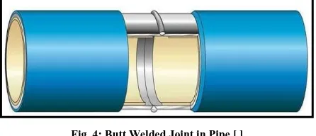
Butt welding is the most common type of welding. It is widely used to join the same diameter pipes. It requires skilled workers to install the joint. These joints are normally used for large commercial and industrial piping systems. Butt weld provides high strength to the joint and it can resist high pressure because of smooth and continuous surface inside the joint. Butt weld joints are costly; to make it cheap sometimes internal weld backing rings are used, which joins the pipe with less amount of filler material. But at heavy stresses these rings may fail and cracks are developed. Butt welding joints are fixed permanently and do not opened for maintenance purposes. It gives smooth & good appearance externally in the piping system.
Fig. 4: Butt Welded Joint in Pipe [ ]
5)Socket Welded Joint
Socket welded joints are used where there is high chance of leakages in joints. As shown in fig. 5 pipes are connected as putting one into other and welded around the joint. The pipes which have different diameters are suitable for this type of joint. For similar diameter pipes, required fittings are used. The welding cost in this case is generally lower than butt welding.
[image:2.595.55.270.214.380.2]Compared to butt welded joints fatigue resistance is low for socket welded joints. However, socket welded joint give good results when they are compared with other mechanical joints.
Fig. 5: Socket Welded Joint in Pipe
B.Welding Process
Welding is a fabrication or sculptural process that joins materials, generally metals or thermoplastics, by causing fusion, which is distinct from lower temperature metal-joining techniques such as brazing and soldering, which do not melt the base metal. In addition to melt the base metal, a filler material is usually added to the joint to form a pool of molten material that cools to form a joint that is usually stronger than the base material. Pressure is used in conjunction with heat, or by itself, to produce a weld.
Some of the best known welding methods include: Shielded metal arc welding (SMAW) – also known as "stick welding or electric welding", uses an electrode that has flux around it to protect the weld puddle. The electrode is held in the electrode holder as it slowly melts away. Slag is protects weld puddle from atmospheric contamination.
Gas Tungsten Arc Welding (GTAW) – also known as TIG (tungsten, inert gas), uses non-consumable tungsten electrode to produce the weld. An inert shielding gas such as argon or helium protected weld area from atmospheric contamination.
Gas Metal Arc Welding (GMAW) – commonly termed MIG (metal, inert gas), uses a wire feeding gun that feeds wire at an adjustable speed and flows an argon-based shielding gas or a mix of argon and carbon dioxide (CO2) over the weld puddle to protect it from atmospheric contamination.
Flux-Cored Arc Welding (FCAW) – is almost same as MIG welding except it uses a tubular wire filled with flux; it can be used with shielding gas or without it, depends on the filler.
Submerged Arc Welding (SAW) – Automatically feed consumable electrode and a blanket of granular fusible flux. The molten weld and the arc zone are protected from atmospheric impurities penetration by being "submerged" under the flux layer.
[image:2.595.53.276.570.666.2]International Journal of Emerging Technology and Advanced Engineering
Website: www.ijetae.com (ISSN 2250-2459, UGC Approved List of Recommended Journal, Volume 8, Issue 4, April 2018)258
Electric Resistance Welding (ERW) – is a welding process that makes combination of laying surfaces where heat to form the weld is generated by the electrical resistance of the material. In general, an effective method, but only limited to relatively thin material.Fig.6: GMAW Circuit Diagram.
(1) Welding Torch, (2) Workpiece, (3) Power Source, (4) Wire Feed Unit, (5) Electrode Source, (6) Shielding Gas Supply.
II. LITERATURE SURVEY
Masoud Pedram, Mohammad Reza Khedmati, have shown the “The effect of welding on strength of aluminum plates subjected to combined uni-axial compression and lateral pressure”. In this work, the results of the sophisticated numerical studies held to investigate the effect of weld on the strength of the aluminum stiffened plates are preselected. The selected finite element models are subject to combined lateral pressure and in-plane compression.
R.H. Leggatt, presented the “Residual stresses in welded structures”. In this paper the nature of residual stresses in welded structures is discussed in terms of their magnitude, directionality, spatial distribution, range and variability. The effects of the factors on the residual stresses are considered are material properties, material manufacture, and structural geometry, fabrication procedure, welding procedure, post-weld treatments and service conditions. The influence of material properties including the coefficient of thermal expansion, the yield strength and phase change has discussed. It has shown that the residual stresses in the three orthogonal directions relative to the weld are systematically different due to the different restraints acting in these directions. The influence of the inherent restraint due to the geometry of the parts being joined and the applied restraint due to welding jigs or the surrounding structure have explored.
Lasse Suominen1, Mansoor Khurshid, Jari Parantainen, presented a paper on “Residual stresses in welded components following post-weld treatment methods”. In this paper residual stresses of the weld area and their modifications for improving the fatigue strength are discussed. The residual stresses from the toe area are changed from tensile to compressive stresses, which are known to make better fatigue strength, with several methods. High tensile stresses can be relaxed mechanically or thermally as post weld heat treatment. In large structures mechanical treatments are more common. Regular mechanical methods are TIG re-melting, burr grinding, hammer peening & needle peeing. Now the new method is laser re-melting method. Above this methods ar change the geometry of the weld toe by improving it. This paper concentrates to needle peening (HFMI, high frequency mechanical impact) and presents some results from laser re-melting tests. Both depth measurements and surface distributions of stress measured by X-ray diffraction method are presented. In this work residual stresses in the weld toe area in high strength steels have been studied. Both depth and surface distributions of residual stresses in as welded and post weld treated weld seams have been measured. Also four samples have been measured after fatigue testing. Post weld treatments HFMI and laser re-melting have been studied. Relative new method low-transformation temperature (LTT) filler material samples have been measured. HFMI method gives clear and strongest effect. Laser treatment has small effect and LTT filler material has practically beneficial effect to the toe area tensile stresses. Results show that thin plate is more sensitive to high tensile stresses than thicker plate. This can be related also to different amount of layers. In the fatigue testing compressive residual stress have relaxed different amount.
International Journal of Emerging Technology and Advanced Engineering
Website: www.ijetae.com (ISSN 2250-2459, UGC Approved List of Recommended Journal, Volume 8, Issue 4, April 2018)259
The minimum longitudinal out of plane distortion was achieved at a heating temperature of 200°C owing to the balance between buckling distortion induced by welding & that generated by static differential heating which resisted the weld distortion. Under such condition, fatigue crack growth resistance was improved. The conclusions that can be drawn from this investigation are summarized as; out of plane distortion shall be reduced by stretching effect generated by static thermal tensioning (STT) treatment which counterbalances the distortion induced by welding. The use of simultaneous cooling & heating during STT treatment modifies weld thermal cycle which affects weld microstructure and static properties such as hardness and strength. Apart from control of distortion STT treatment can be reduced tensile residual stresses & to a certain extent, compressive residual stress is formed.Tso-Liang Teng, Chin-Ping Fung, Peng-Hsiang Chang, Wei-Chun Yang, presented a paper on “Analysis of residual stresses and distortions in T-joint fillet welds”. This study describes the thermal elastic-plastic analysis using finite element techniques to analyze the thermo-mechanical behavior and evaluate the residual stresses and angular distortions of the T-joint in fillet welds. Further more, this work employs the technique of element birth & death to simulate the weld filler variation with time in T-joint fillet welds. Also discussed; the effects of welding penetration depth, flange thickness, & restraint condition of welding on the residual stresses and distortions. This research employs the finite element methods to evaluate angular distortions & residual stresses in T-joint fillet welds. A high tensile stress is produced near the fillet weld toe, in the case of transverse residual stresses. As stress approaches becomes zero at distance from the weld toe increases. For longitudinal residual stresses, a very large tensile stress occurs near the weld toe, and a compressive stress appears away from the weld bead. Along the flange thickness temperature distribution causes fillet weld angular distortions, which bend the flange up. Internal restraints are increased with increasing flange thickness, and the tensile residual stress near the fillet weld toe increases. With increasing heat input in fillet welding or penetration depth, the tensile residual stress near the fillet weld toe decreases, and can also improve non-penetration defects. In a restrain fillet weld, the tensile residual stress and angular distortion near the toe can be reduced after the restraint force is released. When the applied restraint position is changed at the boundary, a mini-mum angular distortion can be obtained.
S.R. Thorat, Dr.Y.R.Kharde, K.C. Bhosale, S.B. Kharde, presented a paper on “Effect of Welding Conditions on Residual Stresses and Heat Source Distribution on Temperature Variations on Butt Welds”.
This Paper concludes that, for the residual stresses distribution in a butt weld, the middle weld bead is in tension and the magnitude of this stress equals to the yield stress. While increasing the specimen thickness, the peak transverse residual stresses in the central region decreases. Similarly, when specimen thickness decreases, the tensile residual stresses in the region near the fusion zone increases. A higher welding speed reduces the amount of adjacent material affected by the heat of the arc and progressively decreases the residual stresses. The magnitude of the residual stresses with a restrained joint is higher than that estimated with an unrestrained joint. The weldment significantly reduces the residual stresses by the application of preheating treatment.
Liam Gannon, Malcolm J. Smith, Neil Pegg Yi Liu - presented a paper on “Effect of welding-induced residual stress and distortion on ship hull girder ultimate strength”. In this paper nonlinear finite element analysis is used to simulate welding of stiffened plates, giving the three-dimensional distribution of welding-induced residual stress and distortion. The load-shortening curves are generated under axial compression load in the welded stiffened plates. These curves are then used as input in a hull girder ultimate strength analysis using Smith’s method. The ultimate strength predicted using IACS curves was significantly higher than the experimental result, whereas that determined using load shortening curves from finite element analysis agreed well with the measured value. Result summarized were, Residual stresses reduced the ultimate strength of the stiffened plate by 11% with a consequent reduction in hull girder ultimate moment of 3.3%. A single applied stress cycle of 0.25sy caused reductions in tensile and compressive residual stress in the stiffened plate of 18% and 11%, respectively. Load-shortening curves generated by analytical methods resulted in overestimates of the box girder ultimate strength. In particular, the methods prescribed in the IACS common structural rules resulted in an ultimate moment capacity 17% higher than the experimental value. This indicates that the current rules used for ship structural design may, in some cases, lead to overestimates of the ultimate longitudinal bending moment capacity of ship hulls.
International Journal of Emerging Technology and Advanced Engineering
Website: www.ijetae.com (ISSN 2250-2459, UGC Approved List of Recommended Journal, Volume 8, Issue 4, April 2018)260
Peak magnitude of the transverse stresses varies between +50 MPa (19% of parent plate proof strength) at the HAZ boundary to _150 MPa (57% of PP proof strength) at the weld centerline. Equivalent values for longitudinal stresses are +90 MPa (34% of PP proof strength) some 22 mm from the weld centerline to _120 MPa (45% of PP proof strength) at the weld centerline. Plate to plate variation in the as welded transverse and longitudinal residual stresses value across the weld toe region is around 40 MPa. The effect on residual stress and strain values of a sequence of applied fatigue loads was also considered and reported.III. OBJECTIVE
1)Impact on Tensile strength: this study will verify impact on tensile strength of material by ANALYSING using ANSYS and validating the obtained results by experimental testing.
2)To identify the product parameter values under the optimal process parameter values and to optimize the settings of the process parameter values for the improving performance characteristics.
IV. FINITE ELEMENT ANALYSIS
Taguchi method is to be used to draw the design of experiments table for the analysis to be performed for 3 levels.
With the combinations mentioned in the table above FEA is conducted to find out pre-stress caused by the welding in the pipe. In three-dimensional (3D) finite element method, heating conditions are accommodated as far as possible using moving distributed heat source and temperature-dependent material properties. For developing the thermal model, all the thermal and
[image:5.595.324.536.318.478.2]mechanical properties are considered as shown in table 1.
Table.1.
Design of Experiments capital & fond side Taguchi
Sr.No. I (A)
V (volts)
G (lit/min)
1 180 23 8
2 180 25 9
3 180 27 10
4 190 23 9
5 190 25 10
6 190 27 8
7 200 23 10
8 200 25 8
9 200 27 9
In this work, the thermo-mechanical analysis is performed to show the heating effects when the molten metal is at melting point temperature at weld root and variation in temperature from weld root to end of the weldments at different time due to conduction and convection. At every time step, the mechanical to the thermal field coupling are very weak in nature, therefore the solution of the non-linear transient problem is divided into two parts. A thermal analysis is performed to predict the temperature distribution of the whole weldment due to conduction and then the temperature field is applied as input for the subsequent mechanical analysis in a staggered approach. Two 1 inch pipes with thickness of 1mm are created in 3 D modelling and 100 mm length of each specimen in created. Welding area is modelled between two specimens as shown in fig. 7.
Fig.7. Geometry of pipe
[image:5.595.77.252.579.726.2]FEA analysis is ran on the specimens model with heat flux calculated from the input parameters and convective coefficient is given to the area above the pipe due to gas flow rate heat flux for different cases varies also heat flow rate. Below is the result for one of the analysis ran and summary is given in the table as shown in figure 8-10 for temperature distribution for case 1 are given in the fig. 11 below for different times. Welding is performed for first 10 seconds and simulation is done for up to component cools down. Temperature plots at different times are given below.
[image:5.595.315.551.618.769.2]International Journal of Emerging Technology and Advanced Engineering
Website: www.ijetae.com (ISSN 2250-2459, UGC Approved List of Recommended Journal, Volume 8, Issue 4, April 2018)261
Maximum temperature of 1266 C is observed only near the weld area.Fig.9. Temperature Case 1 at 50 Seconds Case 1
Fig.10. Temperature Case 1 at 200 Seconds Case 1
Fig.11.Maximum temperature Vs time case 1
Temperature Vs time shows the fig. 11 that it takes around 4 mins for specimen to cool down with the gas flow rate of 8 lit/min. Temperatures from the thermal analysis are imported to the structural analysis and stresses are observed for fixed condition of specimen.
Fig.12. von Mises stress plot at t = 500 sec. case 1
After cooling down maximum area on the weld shows the pre-stress around 25 MPa. Normal Stress is also plotted and variation of the pre-stress away from the weld is also plotted as shown in fig. 14. Maximum of 110.8 MPa is pre stress on the specimen is observed as shown in fig. 13.
Fig.13. Stress Path Line
Fig.14. Von Mises stress plot Vs Distance from the weld case 1
International Journal of Emerging Technology and Advanced Engineering
Website: www.ijetae.com (ISSN 2250-2459, UGC Approved List of Recommended Journal, Volume 8, Issue 4, April 2018)262
Fig.15. Normal stress longitudinal graph of stress vs distancecase 1
Similar to von mises stress variation normal stress variation is observed in the weld and fixing area zones.
Table.2. FEA Results Capital
Sr. No .
Max. Temp (oC)
Max. Eqv. (MPa)
Max. Normal Stress (MPa)
1 1266 180.5 -193.7
2 1364 166.7 -178.9
3 1456 144.8 -155.5
4 1323 165.0 -177.1
5 1436 144.4 -155.0
6 1553 196.8 -211.2
7 1396 143.4 -153.9
8 1512 194.4 -208.7
9 1630 177.9 -190.9
Fig.16 Interval of Maximum Temperature
Fig.17. Main Effect for Maximum Temperature
Fig.18. Main effect for Maximum Pre-Stress
The main effect plot for the three different welding parameters maximum temperature and maximum pre stress has shown in figure 16 and figure 17. Figure 16 shows the main effect plot for work-piece weld temperature for various current voltage and gas flow supply. The results show that with the increase in current there is a increase in temperature value. A voltage of 27 volts gives higher temperature, i.e. the best weld strength. In the figure 17 the optimum value for gas was 8lit/min. and for voltage is 23volts.
International Journal of Emerging Technology and Advanced Engineering
Website: www.ijetae.com (ISSN 2250-2459, UGC Approved List of Recommended Journal, Volume 8, Issue 4, April 2018)263
V. EXPERIMENT VALIDATION
Fig.19: MIG Actual Setup
The MIG Welding machine is used for experimentation for welding galvanized iron pipe of 2 mm thickness joined using AISI 309L wire rod of 1.2 mm diameter. The chemical compositions of AISI 309L & 3Cr12 wire rod are given in Table 1 and Figure 6 shows the MIG welding machine set-up. It is 03-phase, 50Hz frequency and 300A current forced air cooling machine. In the MIG welding process, argon is used for nonferrous metals such as aluminum, nickel, copper, magnesium alloys and reactive metals, such as zirconium and titanium. For ferrous welding process, argon is usually mixed with other gases, such as oxygen or carbon dioxide. In practical application of welding stainless steel, the addition of small amounts of oxygen to argon greatly stabilizes the, increases the filler metal droplet rate, welding arc lowers the spray transition current and influences weld shape. Therefore, experiments were carried out under the shield of mixture of commercial argon (98%) and oxygen gas (2%). In this experimental set-up current changes automatically due the variation in welding voltage. Therefore, the four welding input parameters selected in the present work are the welding voltage (V), Welding Current (A) and gas flow rate (G)
Table.3.
Material composition of Rod and Base capital [ ]
Material (%) 3Cr12 AISI309L
C 0.014 0.02
Si 0.58 0.42
Mn 0.907 1.8
S 0.009 0.01
P 0.012 0.02
Cr 10.625 24.8
Ni 0.794 12.92
Mo 0.043 0.01
Ti 0.144 0.124
V 0.037 0.049
Cu 0.069 0.03
Nu 0.014 0.025
Fe 86.089 59.772
Specimen of inputs 1, 5 and 8 from input table no 2 are manufactured using MIG welding and defined process parameters as described in the process above and they are tested in the UTM machine to find out variation in the load taken by the each component. Graphs below shows the load taken by the specimen 1, 2 and 3 which correspond to input conditions 1,5 and 8 respectively.
Fig.20.UTM testing of the sample loaded condition
Fig.21. Graph of Load vs Displacement Case 1
Actual testing load condition graph of load vs deformation is shown in the figure above, maximum load taken by the component for input condition 1 is observed to be 64.2 KN.
International Journal of Emerging Technology and Advanced Engineering
Website: www.ijetae.com (ISSN 2250-2459, UGC Approved List of Recommended Journal, Volume 8, Issue 4, April 2018) [image:9.595.67.262.170.324.2]264
Figure 22 shows load vs. deformation graph for case 5 as it can be observed for input condition 5 load taken by the component is 72.66 KN before breaking.Fig.23. Load vs deformation specimen 3
Similar to above two diagrams specimen 3 shows the maximum load taken by the case 8 input welded joint which is 62.3 KN.
[image:9.595.315.548.170.345.2]VI. RESULTS AND DISCUSSION
Fig.20. Gas flow vs Equivalent Stress
[image:9.595.54.278.384.532.2]Figure 20 shows the relation between gas flow and the equivalent stress. As gas flow over the work piece increases the von Mises or equivalent stress observed due to welding decreases. The Maximum temperature and inversely true for the normal stress. This is negative in nature due to compressive stress. All the other variables are plotted against each other to form a relation.
Fig.21. Current vs Maximum Temperature Graph
Maximum temperature observed increases with increased current. Same can be plotted and proven for Voltage vs temperature plot as.
Fig.22. Equivalent Stress against current
[image:9.595.316.547.416.575.2]Von Mises stress is increase against the current till 190 A and is decrease afterwards. Same is true with graphs normal stress with current. Below three dimensional graphs of normal stress vs Voltage is given fig. 23
Fig.23. Voltage vs Normal Stress affected by Gas flow rate
[image:9.595.52.278.636.752.2]International Journal of Emerging Technology and Advanced Engineering
Website: www.ijetae.com (ISSN 2250-2459, UGC Approved List of Recommended Journal, Volume 8, Issue 4, April 2018)265
VII. CONCLUSION
Maximum temperature observed in the GMAW process is directly proportional to voltage and current provided (Power input) and is inversely proportional to the gas flow rate of the inert gas over the work piece.
Pre-stress observed in the welded piece due to welding procedure is observed to be highest in the middle range of the current input, it goes on increasing from 180 ampere to 190 A and it is observed to have lower values when current is changed from 190 A towards 200 A.
Voltage increases the stresses due to welding up to the 25 volts and after that it is observed to have constant value of the pre stress. So it can be safely said that maximum pre-stress will be observed at 190 A current , 8 liter/min gas flow and 25 or 27 Volts current and same has been proven in the DOE case 6 results. Maximum von mises stress observed is 196.8 MPa and maximum Compressive normal stress is observed to be -211.2 MPa in FEA. So FEA results table shows 180.5 MPa , 144.4 MPa and 194.4 MPa prestress in condition 1, 5 and 8. Load taking capacity of the component in UTM testing is observed to be 64.2 KN, 72.2 KN and 62.3 KN. So FEA prestress patterns are validated from UTM testing results.
VIII. FUTURE SCOPE
Wider range of voltage, current and Gas flow speeds can be incorporated with sufficient availability of the funds for the experiments and more robust results for the relations between different parameters of the welding process can be find. Instead of steel we can study different materials and different wire diameters. When used with robots we can also vary the welding speed and add in to the study input parameters.
REFERENCES
[1] Masoud Pedram & Mohammad Reza Khedmati, The effect of
welding on the strength of aluminium stiffened plates subject to combined uniaxial compression and lateral pressure. Int. J. Nav. Archit. Ocean Eng., 2014
[2] R. H. Leggatt, “Residual Stresses in Welded Structures”, Science
Direct International Journal of Pressure Vessels & Pipping 85, 2008, 144-151.
[3] Lasse Suominen, Mansoor Khurshid & Jari Parantainen,
“Residual stresses in welded components following post-weld treatment methods”, Science Direct 5th Fatigue Design Conference, Fatigue Design 2013
[4] M.N. Ilman , Kusmono , M.R.Muslih, N. Subeki & H.Wibowo,
“Mitigating distortion and residual stress by static thermal tensioning to improve fatigue crack growth performance of MIG AA5083 welds”, Department of Mechanical and Industrial Engineering, Gadjah Mada University, Yogyakarta, Indonesia. Materials and Design 99 (2016) 273–283.
[5] Reenal Ritesh Chand, Soo Kim, Qian Qian Wu, Bong yong Kang
and JiYeon Shim, “Prediction of Residual Stress and Welding Deformation in Butt-weld Joint for Different Clamped Position on the Plates” International Journal of Engineering Science and Innovative Technology (IJESIT) Volume 3, Issue 5, September 2014
[6] S.R. Thorat, Dr. Y. R. Kharde, K.C. Bhosale , S.B. Kharde,
“Effect Of Welding Conditions On Residual Stresses And Heat Source Distribution On Temperature Variations On Butt Welds : A Review , International Journal of Engineering Research and Applications (IJERA) ISSN: 2248-9622 Vol.03, I st Issue, Jan.-Feb. 2013, pp.1434 -1439.
[7] Liam Gannon , Yi Liu, Neil Pegg & Malcolm J. Smith, “Effect of
welding-induced residual stress and distortion on ship hull girder ultimate strength “,Elsevier Marine Structures 28 (2012) 25–49 [8] Jinxiang Zhang , Kaishin Liu, Kai Zhao , Xiaojie Li,Ying Liu &
Kai Zhang , “A study on the relief of residual stresses in weldments with explosive treatment”, Elsevier International Journal of Solids and Structures 42 (2005) 3794–3806
[9] M.N. James, D.J. Hughes, D.G. Hattingh, G. Mills & P.J.
Webster, “Residual stress and strain in MIG butt welds in 5083-H321 aluminium: As-welded and fatigue cycled, Elsevier International Journal of Fatigue 31 (2009) 28–40
[10] Tso-Liang Teng, Chin-Ping Fung, Peng-Hsing Chang &
Wei-Chun Yang, “Analysis of Residual Stresses & Distortion in T-joint Welds. Elsevier International Journal of Pressure Vessels & Piping 78(2001) 523-538.
This work is supported by Shree Ramchandra College of Engineering, Lonikand, Pune.
A. Mr. Pratap S. Kamble (Student) Department of Mechanical Engineering, Shree Ramchandra College of Engineering, Lonikand, Pune.(E-mail:pratapsarang@rediffmail.com)
B. Prof. Dr. S.G.Taji (Project Guide) Department of Mechanical
Engineering, Govt. Polytechnic Ahmandnagar.(E-mail:
sgtaji@mech.mitaoe.co.in ).
C. Prof.A.B.Verma (Project Co-guide) Department of Mechanical
Engineering, Shree Ramchandra College of Engineering, Lonikand,
![Fig. 1: Threaded Joint in Pipe [ ]](https://thumb-us.123doks.com/thumbv2/123dok_us/8679522.874312/1.595.319.543.592.719/fig-threaded-joint-pipe.webp)