Challenges, Opportunities and Solutions in Structural Engineering and Construction - Ghafoori (ed.) ©2010 Taylor&Francis Group, London, ISBN 978-0-415-56809-8
Structural behaviour of reinforced palm kernel shell foamed concrete beams
u.J.
AlengaramSEGi University College, Malaysia
M.Z. Jumaat &H. Mahmud University of Malaya, Malaysia
ABSTRACT: Experimental results of an investigation conducted to study the structural behaviour of reinforced palm kernel shell foamed concrete (PKSFC) beams prepared using palm kernel shell (PKS) as lightweight aggregates (LWA)are reported. The use offoam in the PKS concrete was to reduce the density ofPKS concrete from 1900kg/rrr' to 1650 kg/m! and at the same time to produce grade 20 concrete using mineral admixtures. 10% silica fume and 5% class F fly ash were used as additional and cement replacement materials respectively in PKSFC, but normal weight concrete (NWC) contained none. The test results show that flexural and shear capacities of the PKSFC beams were found close to that of NWC beams. The PKSFC beams exhibited more cracks within the flexural zone and shear cracks in the shear zone than NWC beams. The deflection of PKSFC was found to be higher than that ofNWC beams.
INTRODUCTION
l.l Use of waste material as lightweight aggregate
Malaysia being the second largest palm oil producer in the world and has total palm tree planted area coverage of 3.8 million hectares. Every year, the production of palm kernel shell (PKS) as a waste from palm oil industry is approximately 4 million tones. The PKS has the potential to be used as coarse aggregate in concrete. PKS is hard and light and hence it can be utilized to replace conventional coarse aggregate to produce lightweight concrete. These types of waste materials, when properly processed, have shown to be effective as construction material.
1.2 Lightweight aggregate foamed concrete RILEM classifies lightweight concrete (LWC) with compressive strength of 15 N/mm2 or more as
struc-tural grade concrete--class-I, and strength between 3.5 and 15 N/mm2as structural and insulating
concrete-class-II (FIP 1983). LWC in the form of aerated con-crete is either a cement or lime mortar, classified as ~ightweightconcrete in which air-voids are entrapped
IIIthe mortar matrix by means of suitable aerating agent (Valore 1954).
The main advantage of aerated concrete is its light-Weight, which economizes the design of supporting structures including foundation and walls of lower floors. For cellular concrete the voids may occupy
anything from 25 to 80 percent of the total volume. As with conventional concrete, the strength of aer-ated concrete depends on its density; in addition, water-cement ratio, addition of admixtures and curing conditions also playa role in strength development. LWC in the forms of LWAC and foamed concrete played a dominant role in the development of LWC as useful construction material. However, only very few literatures are available on the properties of con-crete containing foamed mortar and LWA. Weighler and Karl (1980) conducted experiments on such con-crete that contained light expanded clay aggregates (leca) with foamed mortar. They concluded that the foamed concrete incorporating LWAhas lighter den-sity and good thermal insulating property. This was due to the voids created by the foam inside the con-crete. Thus, for the concrete tested, they found the density and the compressive strength in the range between 700 to 1200kg/rrr' and 5 to 30 Nzmnr',
1.3 Objectives
The objective of this work was to produce palm kernel shell foamed concrete (PKSFC) of grade 20 and to study its structural behaviour with respect to flexure and shear and to compare with that of normal weight concrete (NWr). Two beams one each on PKSFC and NWC were pr pared for testing in flexure. However, to study the shear behaviour, four beams were prepared.
Inaddition two beams on NWC were also prepared for comparison. 1he variable in shear test was the shear span to effective depth ratio (aid).
2 MATERIA:LS
2.1 Cement and mineral admixtures
Ordinary Portland cement conforming to MS 522; Part-l:2003 with specific gravity of 3.10 was used for all mixes m this investigation. 5% of class F fly ash (FA) by cement weight was used as cement
[image:2.462.16.448.30.669.2]a) Palm kernel shell b) Pre-formed foam
Figure I. Palm kernel shell and foam.
replacement. Similarly, 10% of Silica fume (SF) in undensified form with specific gravity of 2.10 was used as additional cementitious material. The use of SF was to develop a good bond between PKS and the cement matrix.
2.2 Fine and coarse aggregates
Mining sand of relative density of 2.7 and of size between 0.15 and 2.36 mm was used as fine aggre-gates. The PKS obtained from local crude palm oil pro-ducing mill were used as coarse aggregates. Figure 1 (a) shows the shells and it can be seen that they possess curved and irregular surfaces.
2.3 Foaming agent and super plasticizer
Synthetic foaming agent (polyoxyethylene alkyl ether tenside) with specific gravity of 1.02 was used in the investigation. It was supplied by BASF, a German based chemical company and diluted in the water in the ratio of 1: 19 to produce foam. The generated sta-ble foam is shown in Figure 1 (b). The superplasticizer (SP), Rheobuild 1000 M with specific gravity of 1.21 was used at about 0.5% by cement weight.
3 SAMPLE PREPARATIONS AND TESTING
3.1 Mix proportion and mixing
The mix design for the PKSFC specimens based on the specific gravities of constituent materials was done. The quantity of foam added was calculated based on the target density of 1650 kg/rn''. However,
~ The clear cover to
rein-forcement =30mm. Effective de th ~ 209mm a) Reinforcement cage for beam in flexure
b) Reinforcement cage for beam in shear for aid=1.0 (For beams with aid=2.0, thelinkspacing was 150 mm c/c)
for NWC concrete, the department of environment (DOE) method was adopted. The following mix ratios were used for PKFSC beams: sand to cement ratio (s/c)
=
1.6; aggregate to cement ratio (a/c)=
0.8; water to binder ratio (w/b)=
0.35; superplasticizer (SP) content=
about 0.5% by cement weight. The cement content for PKSFC was about 370 kg/rrr'. However for NWC, the ratios were in the following order: sic and a/c=
3.6; w /c=
0.75; SP=
0.5%. Cement content for NWC=
260 kg/m '. The mixing was done in the following order: firstly PKS in satu-rated surface dry condition was added with dry sand and mixed in mixer for about 2 minutes. Then one-half of cement and cementitious materials were added and part of water with superplasticizer was added. Then remaining materials were added and mixed.3.2 Beam preparation and Instrumentation
The reinforcement details of beams are shown in Figure 2. Itcan be seen from the sketch that there was no holding bar provided in the pure moment zone for beams in flexure. For beams in shear, the mini-mum shear reinforcement was provided based on the aid ratio of 1.0 and 2.0. The clear cover for all beams was 30 mm. Companion concrete specimens were cast to study the mechanical properties of PKSC. Com-pressive strength of 100 mm cubes, flexural strength of 100 x 100 x 500 mm prisms and splitting tensile strength on 150 mm diameter x 300 mm height cylin-ders have been carried out. All beams designed using BS8110-Part 1: 1997 were cast in steel moulds. They were vibrated using internal vibrator and covered with jute clothes for 28 days and cured. Afterwards the beams were kept under laboratory condition till the
day of testing at the age of about 60 days. An Instron machine with a built in capacity of 500 kN load cell was used in testing of beams. The tensile and com-pressive strains of both reinforcement and concrete were measured through electrical resistance gauges. All the strains were recorded using data logger. In addition, the strain distribution on the vertical face of the beams in the flexural zone was determined using de-mountable digital extensometer with a sensitivity of 0.00 1 mm. Three linear voltage displacement trans-ducers (LVDT) were placed, one at centre of beams, the other two under load points, to measure the deflec-tions at centre and under load points for beams in flexure. For beams in shear, the vertical deflections were measured under the load single point load was applied for beams tested in shear. However, two-point loads were applied for beams in flexure. All strain, crack width and deflection measurements were mea-sured at every load increment. Table I and Table 2, respectively show the details and concrete and steel properties of beams tested in flexure and shear. The beams tested in flexure and shear are designated as FB and SH, respectively. Similarly, the materials are indi-cated as NWC and PKSFC for normal weight concrete and palm kernel shell foamed concrete, respectively.
3.3 Properties of PKS
The natural moisture content and 24 hour water absorption of PKS were determined. The thicknesses and the size ofPKS were also measured. The particle size distribution and the specific gravity were deter-mined. The loose and compacted densities were also found. The results ofPKS are shown in Table 3.
Table I. Details of beams tested in flexure and shear. Table 3. Physical property of palm kernel shells.
Beam Type of No of Properties
Values designation Material test beams aid
*
FB-PI PKSFC Flexure I 3.11 Size (mm) 2-15
FB-NI NWC Flexure I 3.11 Thickness (mm) 1.0-3.0 SH-PI &P2 PKSFC Shear 2 1.0 Bulk density (loose) (kg/m ') 568 SH-NJ NWC Shear I 1.0 Bulk density (compacted) (kg/m ') 620 SH-P3 &P4 PKSFC Shear 2 2.0 Specific gravity 1.27 SH-N2 NWC Shear I 2.0 Water absorption (I hour) (%) 12
Water absorption (24 hour) (%) 25
• Shear span to effect depth ratio.
Table 2. Details of concrete properties and reinforcement details (for beams in flexure and shear).
Saturated Cube Modulus Young's Overall Main bar size (mm)
density Slump strength of rupture modulus beam yield strength Steel ratio, Material (kg/m") (mm) (N/mm2) (Nzrnrrr") (kN/mm2) size (mm) (N/mm2) p=As/bd (%) NWC 2341 76 23.78 3.44 27.0 152 x 251 2T-IO for flexure 0.5
4 RESULTS AND DISCUSSION
4.1 Mode offailure
4.1.1 Beams inflexure
The flexural behaviour test on two beams, FB-P1 (PKSFC) ano FB-N1 (NWC) were conducted using lnstron testin machine. A comparison of test results between the PKSFC and the NWC was also made. In order to ensure flexural failure, the shear and compression reinforcement were not provided in the middle-third. The spacing of link was kept at 70 mm to obtain typical flexural failure. The beams were designed as under-reinforced, so steel bar yields first before the contpressive failure occurs in the concrete. In the experiment, both beam shown typical flexural failures as yielding of steel took place followed by concrete crushing at compression zone. Since PKSFC was weaker than NWC, the compression zone of PKSFC had larger crushing area compared to NWC as shown in Figure 3.
4.1.2 Beams in shear
For the shear capacity test, the varying shear span (a) to effective depth (d) ratio of, ajd
=
1 andajd=
2, was adopted. Three beams for each case have been tested to study the shear behaviour. The spacing oflink for beam with aid=
1 and aid=
2 has been calcu-lated based on BS 8110: 1997. Ithas been found from shear testing, th tflexural cracks occur in the begin-ning followed by shear cracks near the support. The shear cracks start in the shear zone near the support and propagated towards the load point, but ultimately the beams failed in flexure due to the higher shear resistance of the beams. One possible explanationa) PKSFC beam
Figure 3. Flexural failure of beam.
for higher shear resistance could be the aggregate interlock of the PKS that contribute to shear resis-tance. In addition, the link spacing that was provided based on BS had sufficient shear resistance to prevent shear cracks. The modes of shear failure for beams are shown in Figure 4. The failure ofNWC was sud-den and brittle in contrast to the ductile failure of the PKSFC. This was the one of the main findings and also an advantage as PKSFC gives adequate warning before failure. As reported by Kong (1995), for shear span to effective depth ratio between 1 and 2, the shear cracks start independently and not as development of flexural cracks. This was observed in experiments and thus PKSFC and NWC beams behaved similar manner.
Inshear test, some cracks started as flexural cracks, and then converted into shear crack. Therefore, a lot of cracks, so called flexural-shear cracks occurred. Shear crack was usually propagated faster than flexural crack although the links had been provided to resist it. Thus shear failure behaved in brittle manner compared to that of ductile failure mode of flexural failure.
4.2 Failure load
4.2.1 Beams inflexure
From Table 4, it can be seen that the first crack load of PKSFC beam, FB-P1 was lower than NWC. This is significant as it was shown earlier that PKSFC had lower modulus of rupture than NWC. Inaddition, the PKSFC was ductile material as compared to NWC that fails in brittle manner. Ductile behaviour of PKS made PKSFC to behave more elastic than NWC. Therefore, the first crack load of PKSFC was found lower than NWC. However, the number of cracks
b) NWCbeam
a) Shear crack pattern for aid
=
IFigure 4. Shear crack patterns for beams in shear.
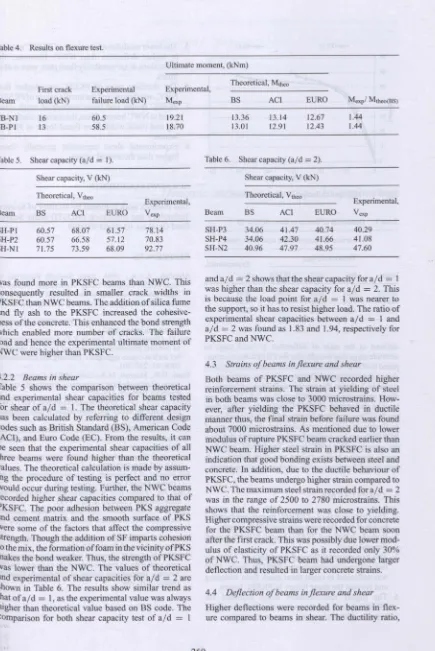
Table 4. Results on flexure test.
Ultimate moment, (kNm)
Experimental, Theoretical, Mtheo First crack Experimental
Beam load (kN) failure load (kN) Mexp BS ACI EURO
FB-Nl 16 60.5 19.21 13.36 13.14 12.67 FB-P1 13 58.5 18.70 13.01 12.91 12.43
Mexpl Mtheo(BS)
1.44 1.44
Table 5. Shear capacity (aid =1). Table 6. Shear capacity (aid =2).
Shear capacity, V (kN) Shear capacity, V (kN)
Theoretical, Vtheo Theoretical, Vtheo
Experimental, Experimental,
Beam BS ACI EURO Vexp Beam BS ACI EURO Vexp
SH-P1 60.57 68.07 61.57 78.14 SH-P3 34.06 41.47 40.74 40.29 SH-P2 60.57 66.58 57.12 70.83 SH-P4 34.06 42.30 41.66 41.08 . SH-N1 71.75 73.59 68.09 92.77 SH-N2 40.96 47.97 48.95 47.60
was found more in PKSFC beams than NWC. This consequently resulted in smaller crack widths in PKSFC than NWC beams. The addition of silica fume and fly ash to the PKSFC increased the cohesive-ness of the concrete. This enhanced the bond strength which enabled more number of cracks. The failure load and hence the experimental ultimate moment of
NWc were higher than PKSFC.
4.2.2 Beams in shear
Table 5 shows the comparison between ·theoretical and experimental shear capacities for beams tested for shear of aid = 1. The theoretical shear capacity has been calculated by referring to different design codes such as British Standard CBS), American Code (ACI), and Euro Code (EC). From the results, it can be seen that the experimental shear capacities of all three beams were found higher than the theoretical values. The theoretical calculation is made by assum-ing the procedure of testing is perfect and no error Would occur during testing. Further, the NWC beams recorded higher shear capacities compared to that of PKSFC. The poor adhesion between PKS aggregate and cement matrix and the smooth surface of PKS Were some of the factors that affect the compressive strength. Though the addition of SF imparts cohesion to the mix, the formation offoam in the vicinity ofPKS rnakes the bond weaker. Thus, the strength of PKSFC Was lower than the NWC. The values of theoretical and experimental of shear capacities foraid
=
2 are shown in Table 6. The results show similar trend as that of al d=
1, as the experimental value was always higher than theoretical value based on BS code. The comparison for both shear capacity test of aid=
Iand aid
=
2 shows that the shear capacity for aid=
1 was higher than the shear capacity for aid=
2. This is because the load point for aid = 1 was nearer to the support, so it has to resist higher load. The ratio of experimental shear capacities between aid=
I andaid
=
2 was found as 1.83 and 1.94, respectively for PKSFC and NWC.4.3 Strains of beams inflexure and shear
Both beams of PKSFC and NWC recorded higher reinforcement strains. The strain at yielding of steel in both beams was close to 3000 microstrains. How-ever, after yielding the PKSFC behaved in ductile manner thus, the final strain before failure was. found about 7000 microstrains. As mentioned due to lower modulus of rupture PKSFC beam cracked earlier than NWC beam. Higher steel strain in PKSFC is also an indication that good bonding exists between steel and concrete. In addition, due to the ductile behaviour of PKSFC, the beams undergo higher strain compared to NWC. The maximum steel strain recorded for a/ d
=
2 was in the range of 2500 to 2780 microstrains. This shows that the reinforcement was close to yielding. Higher compressive strains were recorded for concrete for the PKSFC beam than for the NWC beam soon after the first crack. This was possibly due lowermod-ulus of elasticity of PKSFC as it recorded only 30% of NWC. Thus, PKSFC beam had undergone larger deflection and resulted in larger concrete strains.
4.4 Deflection of beams inflexure and shear
_FB-NI
~40+---~---~
-e
~30
+-~~---~
...JIQ 20 30 40 Deflectien (mm)
[image:6.457.27.441.1.682.2]50
Figure 5. Mid- pan deflection of beams in flexure.
Table 7. Deflection of beams in shear (ajd =2).
Service deflection under load point (mm)
Theoretical, Othe.
Experimental,
Beam BS ACT EURO oexp
SH-P3 6.84 6.97 8.09 6.01 SH-P4 7.02 7.06 8.28 4.29 SH-N2 4.55 4.02 5.10 2.78
defined as the ratio of deflection at yield stage to ultimate stage was found twice for PKSFC beams com-pared to NWC beam in both flexure and shear. Figure 5 shows the mid-span deflection of beams in flexure.
Table 7 shows the service deflection of beams in shear under the load point for aid
=
2.0. The exper-imental deflections of PKSFC beams are higher than the NWC beams. Based on the ductility ratio of beams in flexure, it can be concluded that the behaviour of PKSFC beam has higher ductility characteristics than the corresponding NWC beam. The PKSFC will give ample warning before failure and such behaviour is best suited for structures in earthquake prone region.5 CONCLUSIONS
I. The first crack load ofPKSFC beams was found to be lower than the corresponding NWC beams. 2. Both the NWC and PKSFC beams failed in typical
flexural mode.
3. The experimental flexural capacities of the shear link spacing calculated using BSSII 0: Part I:1997 was sufficient to resist shear crack from widening and prevent the shear failure in PKSFC beams. 4. The higher reinforcement strain recorded for
PKSFC beams in flexure shows that the bond between PKS and cement paste is stronger.
5. The lower modulus of elasticity ofPKSFC resulted in higher deflection than NWC. However, the deflections at serviceability limit state were within limits.
6. The ductility ratio of PKSFC was higher than NWC, and thus proved the ductile nature ofPKSFC. 7. PKSFC beams had more number of crack
com-pared to NWC beams. Thus, the average crack spac-ing and crack width were found lower in PKSFC beams.
S. Experimental shear capacities generally found higher than theoretical values.
60
ACKNOWLEDGEMENTS
This research work is funded by Ministry of Science, Technology and Innovation (MOST!) under Science Fund Grant no. 03-01-03-SF0309.
REFERENCES
Abdullah, A.A.A., 1984. Basic Strength Properties of Lightweight Concrete Using Agricultural Wastes as Aggregates, Proceedings of International Conference on Low-cost Housing for Developing Countries, Roorkee, India.
ACI manual of concrete practice, Part 3-2002, American Concrete Institute 2002.
Ata,0.,Olanipekun, E.A., Oluola, K.O. A comparative study of concrete properties using coconut shell and palm ker-nel shell as coarse aggregates. Building and Environment 2006;41:297-301.
Basri, H.B., Mannan, M.A., Zain, M.EM. Concrete using waste oil palm shells as aggregates. Cement and Concrete Research 1999; 29: 619-622.
BS 8110: Part I: 1997. Structural use of concrete. Part I. Code of practice for design and construction, British Standards Institution 1997.
BS 8110: Part 2: 1985. Structural use of concrete. Part2. Code of practice for special circumstances. British Standards Institution 1985.
Eurocode 2: Design of concrete structures; Part I General rules and rules for buildings, 1992.
FlP Manual of Lightweight Aggregate Concrete, 2nd ed. London: Surrey University Press; 1983.
Kong, EK., Evans, R.H. Reinforced and Prestressed Con-crete, 3rd edn. Chapman &Hall; 1995.
Okafor, EO. Palm kernel shell as a lightweight aggregate for concrete. Cement and Concrete Research 1988; 18: 901-910.
Valore, R.C. Cellular concretes-physical properties. J Am Concr Institute. 1954; 25: 817-836.
Weighler, H., Karl, S. Structural lightweight aggregate con-crete with reduced density-lightweight aggregate foamed concrete. International Journal of Lightweight Concrete