2019 International Conference on Information Technology, Electrical and Electronic Engineering (ITEEE 2019) ISBN: 978-1-60595-606-0
Numerical Simulation of Propagation Process of Acoustic Emission
Partial Discharge Signal in Medium Voltage Switch-Gears
Lei CHU
1, Ding-ge YANG
2, Shuang-zan REN
2, Xue-feng OU
3,
Zhan-hong WANG
1, Bin WANG
1,
Hao WU
2, Jie LIU
3, Bo NIU
2,
Wen-hui LI
2and Li-jun WANG
31State Grid Weinan Power Supply Company, Weinan, 714000, Shanxi, China
2Electric Power Research Inst. of Shanxi Power Grid Corp., Xi’an, 710049, Shanxi, China
3State Key Laboratory of Electrical Insulation and Power Equipment, Xi’an Jiaotong University, Xi’an, 710049, China
Keywords: Numerical simulation, Acoustic emission, Medium voltage switch-gears, Partial discharge.
Abstract. The rapid and accurate detection of partial discharges (PD) ensures the safe operation of the power grid. It is important to improve the reliability of power supply. When a partial discharge (PD) occurs, acoustic wave will be produced. Usually the partial discharge (PD) produces an acoustic wave frequency of about a few kHz in the gas. This article will use the acoustic simulation module in the Comsol Multiphysics software to simulate the propagation of ultrasonic waves inside and outside the switchgear. Since the transmission of ultrasonic waves is affected by many factors, the geometry of the switchgear is the main factor affecting the propagation of ultrasonic waves. Therefore, this paper will simulate the transmission process of ultrasonic waves under different conditions. Exploring the impact of different monitoring locations on monitoring results through simulation. Through the analysis of the simulation results of the ultrasonic propagation process, we got the following conclusions. As the thickness of the switchgear cabinet increases, it only affects the amplitude of the signal. Opening a hole in the cabinet of the switchgear makes it easier to detect ultrasonic signals outside the cabinet. As the number of openings in the cabinet of the switch cabinet increases, the amplitude of the signal monitored outside the cabinet increases. Four monitoring points are placed on the front, back, upper and lower sides of the switchgear cabinet. Through the simulation of the ultrasonic transmission process, it can optimize ultrasonic testing method and provide guidance for the detection method of ultrasonic waves in production activities.
Introduction
Medium voltage switchgear (MVS) is a commonly used device in power systems due to its small size, high economy and good insulation. However, the demand for electrical energy is increasing, making it more susceptible to inherent insulation defects that can lead to fatal insulation failures [1]. Due to the influence of electrical, thermal, chemical and other factors, electrical equipment must have insulation degradation during long-term operation, which in turn causes partial discharge (PD). Partial discharge refers to a partial discharge process that occurs inside a solid insulation or on a surface that does not penetrate the electrode. In the early stage of equipment insulation degradation, there is often a partial discharge phenomenon, and this partial discharge itself will further accelerate the deterioration of the insulation. Because partial discharge is only partial breakdown of the insulation, each discharge will have slight damage to the insulation. Because of the majority of cases of switchgear failure caused by partial discharge, it is of great significance to study and monitor the partial discharge of high voltage switchgear [2,3].
necessary to carry out state maintenance [4,5]. Researches had been dedicated to study the measurements of partial discharge (PD) in electrical equipment for decades, and many technologies were well established such as acoustic emission (AE) method, ultra high frequency (UHF) method, transient earth voltage (TEV) method and phase resolved partial discharge (PRPD) method [6].
When partial discharge occurs, in the discharge region, the molecular motion is intense and collides with each other, and acoustic waves are generated macroscopically, and acoustic waves having a frequency greater than 20 kHz are generally referred to as ultrasonic waves. A method of determining a partial discharge by detecting an ultrasonic signal generated by partial discharge is called a partial discharge acoustic emission (AE) method. Systematic investigations on the application of acoustic emission (AE) method were conducted by Lundgaard [7], who concluded that it was effective in PD detection and location. Besides, Lundgaard recommonded to combine the AE with electrical detection methods for higher accuracy and effeciency. This article will numerically simulate the propagation of acoustic waves inside the switch cabinet to provide guidance for acoustic emission (AE) method.
Establishment of Simulation Model
COMSOL Multiphysics is a versatile engineering simulation software platform. Its core products can be operated separately or in combination with any combination of modules to simulate product design and processes in electromagnetic, structural mechanics, acoustics, fluids, heat transfer, chemical and other fields. The simulation of acoustic wave propagation in the time domain was carried out. The Acoustic Simulation Module in COMSOL Multiphysics provides a basic framework for simulating acoustic wave propagation quickly and easily [8]. The dominant equation is as follows:
2 2 2 2 1 1 m p p Q
ρc ρt ρ
(1)
where ρ is the density of the medium, c is the speed of acoustic in the medium, p is the acoustic
pressure, and Qm is the source. c=343m/s.
Considering that three-dimensional problems require computational precision required by massive computational grids and time domain analysis, in acoustic simulations, in order to resolve acoustic waves, at least four grid nodes are required for one wavelength. Make N=5, c=343m/s, acoustic frequency f = 5kHz, The maximum width of the grid h≈1.38cm. The size of the real switchgear is undoubtedly too large for simulation, so we chose a reduced size as the simulation area. Size is 8cm 5cm 16cm.
Since the transmission of acoustic waves is affected by many factors, the geometry of the switchgear is the main factor affecting the propagation of acoustic waves. Therefore, this paper will simulate the transmission process of acoustic waves under different conditions, such as the size of the switchgear, the thickness of the switch cabinet, the presence or absence of the openings, the number of the openings.
Simulation Process and Result
Characteristics of Sound Wave Propagation
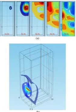
(a)
(b)
Figure 1. (a) Propagation of sound waves inside the switchgear (b) Propagation of sound waves outside the switchgear.
The Effect of the Number of Openings in the Switchgear on the Transmission of Sound Waves
[image:3.595.180.433.67.440.2]As shown in Figure 2, when the hole is opened on one side, the structure of the metal cabinet changes, and a window for sound wave leakage is provided. After the point source sound wave is generated, it expands to the periphery. After encountering the metal cabinet wall, a part of the interior is reflected and superimposed, and a part is transmitted out.
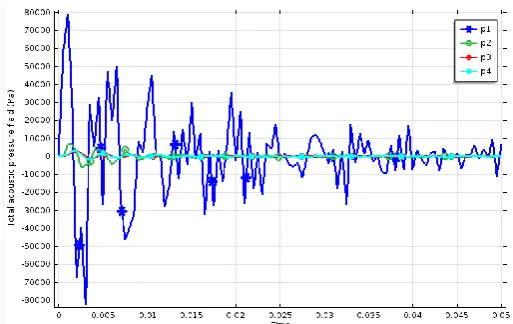
[image:3.595.160.448.555.752.2]Figure 3. The sound signal of each detection point when the switch cabinet has only five openings.
Fig. 2 is a graph of signal changes over time at four detection points. First, the signal intensity of the 1 detection point and the 2 detection point close to the opening is about 5 to 6 times that of the non-opening, and the initial amplitudes of the detection points 3 and 4 are slightly increased. Second, the frequency of the signal changes from about 60 Hz to 13.3 Hz (cycle is 0.075). Finally, the high-frequency components of the signals of the detection points 1 and 2 are many, and the signals have irregular shapes. The maximum amplitude of the signal at detection point 1 indicates that the detection is most advantageous here.
Shown as Fig. 3, the signal amplitude of the detection point 1 is much larger than the signal amplitude of several other detection points. The sound wave signal penetrates from the hole and radiates to the outside, the energy is quickly dissipated, and the signal amplitude of the detection points 2, 3, and 4 drops rapidly. So increasing the opening is beneficial for testing.
[image:4.595.165.445.549.735.2]Influence of Wall Thickness of Switch Cabinet on Acoustic Signal Propagation
Fig. 4 is the acoustic signal of each detection point outside the cabinet when the wall thickness is changed to 2 cm. Increasing the wall thickness only affects the amplitude of the signal. This is because both the wall thickness and the wavelength are on the order of centimeter, and increasing the wall thickness hinders the diffraction of the sound waves. If the wall thickness is much smaller than the wavelength, the diffraction effect of the acoustic wave is significant, and increasing the wall thickness within a suitable range (ensuring that the wall thickness is much smaller than the wavelength) has less influence on the signal.
Conclusion
Simulation results on propagation process of acoustic emission in medium voltage switchgear were summarized in this paper. In the Comsol Multiphysics acoustic module, the switch cabinet is built by three-dimensional (3D) modeling and meshed in this module. The influence of the number of opening of the switchgear and the wall thickness of the switchgear on the acoustic signal propagation is also discussed.
(1) Four monitoring points are placed on the front, back, upper and lower sides of the switchgear cabinet. The most recent monitoring point from the acoustic source detects the ultrasonic signal first, and the signal detected by the monitoring point which is close to the opening of the box has the largest amplitude.
(2) As the acoustic signal is transmitted from the hole and radiated to the outside, the energy is quickly dissipated, and the amplitude of the signal detected by the external detection point drops rapidly. It can be found that the opening is more favorable for the detection.
(3) Increasing the wall thickness only affects the amplitude of the signal. If the wall thickness is much smaller than the wavelength, the diffraction effect of the acoustic wave is significant, and increasing the wall thickness within a suitable range (ensuring that the wall thickness is much smaller than the wavelength) has less influence on the signal.
References
[1] Lijun Wang, Wenjun Ning, Experimental Investigation of Partial Discharge Measurement with Multiple Sensors in Medium-Voltage Switchgear, C. 2014 International Symposium on Discharges and Electrical Insulation in Vacuum (ISDEIV). 28 Sept.-3 Oct. 2014, Mumbai, India.
[2] Z. Berler, I. Blokhintsev, A. Golubev, Partial discharge on-line monitoring in switchgears and bus ducts, C. IEEE 7th International Conference on Solid Dielectrics, June 25-29, 2001, Eindhoven, the Netherlands.
[3] R.G.A. Zoetmulder, S. Mijer, J.J. Smit, Conditional based maintenance with on-line partial discharge measurements of HV and MV switchgear systems, C. 17th International Conference on Electricity Distribution, May 12-15, 2003, Barcelona.
[4] G. J. Paoletti and A. Golubev, Partial discharge theory and technologies related to medium-voltage electrical equipment, J. Industry Applications. 37(2001)90-103.
[5] B. Qi, C. Li, Z. Xing, and Z. Wei, Partial discharge initiated by free moving metallic particles on GIS insulator surface: severity diagnosis and assessment, J. Dielectrics and Electrical Insulation. 21(2000)766-774.
[6] M.M. Olivieri, W.A. Mannheimer, A.P. Ripper-Neto, On the use of acoustic signals for detection and location of partial discharges in power transformers, C. IEEE International Symposium on Electrical Insulation, April 2-5,2000, Anaheim, CA, USA.
[7] A. Deshpande, H. Mangalvedekar, and A. Cheeran, Partial discharge analysis using energy patterns, J. International Journal of Electrical Power & Energy Systems, 53(2013)184-195.