2019 International Conference on Computer Science, Communications and Big Data (CSCBD 2019) ISBN: 978-1-60595-626-8
Test System Based on PLC Control for Intelligent Water Injection Tool
Guang-zheng JIA
*, Qian GAO, Guang-xu PAN, Yu-xi LI and Guan-peng JING
Machinery Science and Engineering College, Northeast Petroleum University, Daqing, China
*Corresponding author
Keywords: Intelligent Water Injection Tool, Test System, PLC Control; Electro-hydraulic Control.
Abstract. In order to provide a simulating environment for water injection tool test, a set of test system controlled by PLC was developed, including the high-pressure water output unit, the flow detection unit, the simulating wellbore unit, the bypass unit and the back pressure unit. The remote monitoring of the test system was realized by using MCGS configuration software, combining with sensors, PLC and industrial PC. It can acquire, store and display experimental data in real time and make the evaluation of the work performance of the intelligent water injection tool more comprehensive and intuitive. The characteristics and functional principle of the system are introduced, and the flow and pressure control are verified to meet the design requirements through some function experiments.
Introduction
Oilfield water injection is the key technology to maintain reservoir pressure and to increase oil recovery, as well as realize stable oil extraction production [1-4]. When oilfield development is in mid and later period, the original water injection technology has gradually shown great disadvantages in some high water content stratum and even super high water content stratum [5], so it has been developed from the original general water injection to the separate zone water injection
[6]
. It mainly includes fixed separated zone water injection, movable separated zone water injection, eccentric separated zone water injection, concentric integrated separated zone water injection and bridge eccentric separated zone water injection, etc [2-5]. In order to solve the problem of low efficiency caused by repeatedly measuring and dropping-fishing water injection nozzles, intelligent water injection technology rises in response to the proper time and conditions [7]. It processes from running and pulling pipe strings and nozzles repeatedly to regulating injection volume from the ground. In order to improve the measurement and regulation efficiency, an electro-hydraulic controlled test system based on PLC is introduced in this paper, which is significant to the development and application of intelligent water injection tools.
Composition
Function and Principle
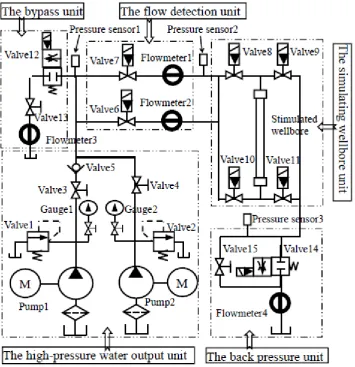
This test system mainly includes high-pressure water output unit, flow detection unit, simulating wellbore unit, bypass unit, back pressure unit and so on, as shown in Fig. 1.
The high-pressure water output unit is composed of two plunger pumps driven by 55kW converter motor, which can provide different power fluid to the test system. The pump 1 is 3DY-11500/12 type with 0~10 MPa pressure and 0~360m3/d flow rates, and the pump 2 is 3DY-6000/28 type with 0~25 MPa pressure and 0~100m3/d flow rates. The valve 1 and valve 2 can control pressure within safe limits. The gauge 1 and gauge 2 can display output pressure values. The valve 3 and valve 4 are manual high-pressure ball valves. The valve 5 is high-pressure check valve. The pressure sensor 1 can measure pumps outlet pressure.
The flow detection unit including two branches that consist of hydraulic controlled high-pressure valve 6 and valve 7, DN10/25MPa electromagnetic flowmeter 1 and DN32/25MPa electromagnetic flowmeter 2 can be used for alternative flow rate measurement.
valve 8, valve 9, valve 10 and valve 11. The pressure sensor 2 is used to measure the wellbore inlet pressure. When the tested intelligent water injection tool is installed in the simulating wellbore, if upper inlet valve 8 and bottom outlet valve 11 are opened, the forward flow experiment can be realized. In a similar way, the bottom inlet valve 10 and the upper outlet valve 9 can be opened to realize the reverse flow experiment.
The bypass unit includes a hydraulic controlled high-pressure regulating valve 12, a manual high-pressure ball valve 13 and a DN25/4MPa electromagnetic flowmeter 3. It can regulate the flow rate coordinating pumps to meet the test and flow calibration conditions.
[image:2.595.128.484.228.596.2]The back pressure unit consists of a pressure sensor 3, a hydraulic controlled back pressure valve 14, a manual high-pressure ball valve 15 and a DN32/ 4 MPa electromagnetic flowmeter 4. It can adjust to the pressure and provide the simulating down-hole stratum condition.
Figure 1. Process control schematic diagram of water injection tool test system.
This test system can set up the simulating test environment, collect and monitor the experimental data in real time, and quantitatively evaluate the flow control performance of the tools under the set pressure. The flowmeter built in the intelligent water injection tool can calibrate on-line, and the pressure bearing performance of the tools can be tested experimentally.
Hydraulic System
The test system adopts electro-hydraulic control mode. The hydraulic system includes hydraulic power source unit, flow detection unit driven by hydraulic cylinder, bypass unit driven by hydraulic cylinder and hydraulic controlled back pressure valve unit. It is easy to operate, responds rapidly and can execute on- off commands reliably, its principle is shown in Fig. 2.
The changing-over of the flow direction can be automatically controlled by computer program or manually clicked by the operator on the computer monitoring interface, which can be operated conveniently and quickly. Valve12 is installed on the bypass branch of the high-pressure pipe manifold, which can make 0~6m3/h flow regulation and over-pressure unloading of the system realized. By cooperating with the accumulator, valve14 can provide backpressure experimental environment as needed. When backpressure is not required, valve15 can be manually opened to smooth the return pipeline.
Figure 2. Hydraulic schematic diagram of intelligent water injection test system.
Control Design
Composition and Process
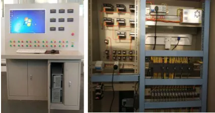
The upper computer adopts industrial PC of the Yanhua Technology and the lower computer uses PLC S7-200 module of the Siemens. The experimental pressure and flow detection signals are input to the analog input module of PLC through the pressure sensor and the flow sensor. Then it is transmitted by communication to the industrial PC for display, storage, processing and printing out. According to the configuration monitoring interface and the PLC control program, the industrial PC outputs the related control instructions through the digital or analog value of the PLC and controls the actuator to operate as required. So far the data acquisition and control are completed.
PLC control Module and I/O Assignment
The control of the test system includes the transfer of digital signals such as pump start-stop and valve on-off, the acquisition of analog signals such as pressure sensor and flow sensor as well as the output of analog control signals such as frequency converter and proportional electromagnetic valve. It needs 28 digital inputs, 15 digital outputs, 9 analog inputs and 3 analog outputs in total. Therefore, CPU224XP, EM221, EM222, EM231(2) and EM232 are selected as the control module. CPU 224XP, the core unit of the control part, with other expanding modules can meet the requirements of signal acquisition and control output of the control system. The control system of real product is shown in Fig.3.
[image:3.595.190.404.669.781.2]The PLC modules, the switch power supply, the digital display instrument, the relays and the control buttons are set and connected according to the wiring diagram, the communication between the PLC and the industrial PC is built through the special cable, the PLC control program combining with the internal configuration monitoring program can realize the remote control and monitoring of the whole experiment system. The buttons and display instruments on the console are not controlled by the computer to make the test system more convenient by debugging device and displaying experimental data independently.
Configuration Monitoring Design
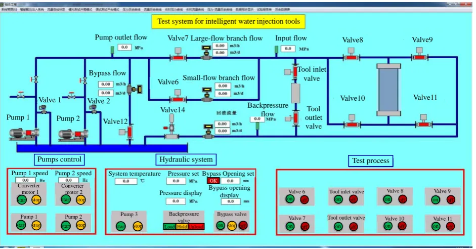
[image:4.595.64.535.294.540.2]The monitoring interface of the test system is built based on MCGS configuration software, as shown in Fig. 4. It can realize the setting of the working speed of plunger pumps, bypass flow rate and back pressure. It can display the pressure and temperature of hydraulic system, pump outlet pressure, small-flow test branch flow rate, large-flow test branch flow rate, inlet pressure, outlet pressure, flow rate of backpressure circuit, bypass flow rate, flow state of pipeline fluid as well as working state of each pump and valve. The start-stop or on-off action of the controlled devices and components can be realized by operating buttons.
Figure 4. Configuration monitoring interface.
System Function Test
Flow Control Range
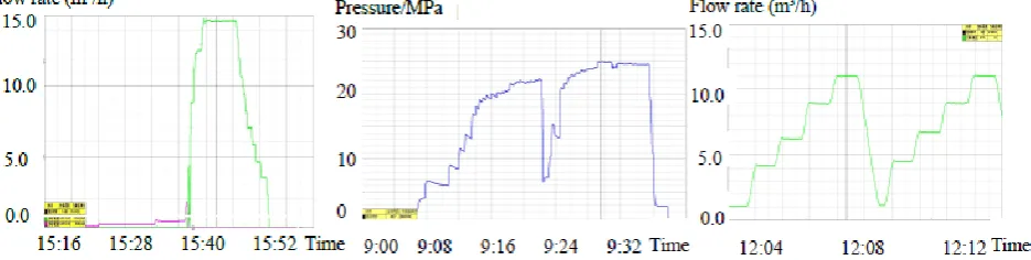
The detection circuit comprises two branch pipelines connected in parallel, and the automatic changing-over of flow detection range is carried out through the valves set on each branch. The measurement range of the small-flow test circuit is 0.08-2.0m3/ h, and the measurement range of the large-flow test circuit is 1.6-15m3/ h, so the system can measure the flow in the range of 0.08-15m3/ h, as shown in Fig.5.
Pressure Test
The pressure curve of the detection circuit is shown in Fig 6. It is known that the system pressure can be stabilized at 25 MPa after the bypass valve is re-adjusted its opening displacement at around the experiment time 9:24. This is due to the dynamic balance of the backpressure valve by the accumulator, which makes the pipeline have the function of pressure maintaining. So it can meet the requirements of the test condition.
Valve9 Test system for intelligent water injection tools
Valve8
Valve10 Valve11 Valve6
Valve7
Valve14 Valve12
Pump 1 Pump 2 Valve 1 Valve 2
Pump outlet flow
Bypass flow
Large-flow branch flow Input flow
Small-flow branch flow
Test process Hydraulic system Pumps control Backpressure flow Tool inlet valve Tool outlet valve
Pump 1 speed Pump 2 speed
Converter motor 1
Converter motor 2
Pump 1 Pump 2
System temperature Pressure set
Pressure display
Bypass Opening set
Bypass opening
display Valve 6
Valve 7
Valve 8 Valve 9
Valve 10 Valve 11 Tool inlet valve
Tool outlet valve Pump 3 Backpressure
valve
Bypass valve OK
start stop
on off start start stop
start stop start stop stop
on on on on
on on on on
off off off off
off off off off
Flow Parameter Calibration
[image:5.595.65.533.153.271.2]After pre-installing the tested and calibrated intelligent water injection tool into the simulating wellbore from the top of it, start the control system and operate related instructions or preset calibration parameters in the computer monitoring interface as the requirements of the tool parameters. The calibration curve is shown in Fig. 7.
Figure 5. Flow measurement curve. Figure 6. Experimental pressure curve. Figure 7. Flow calibration curve.
Conclusion
(1) A set of test system for intelligent water injection tool was built, which was composed of high pressure water output unit, flow detection unit, simulating wellbore testing unit, bypass unit and back pressure unit, etc. The key elements adopted the electro-hydraulic control mode, making the quick response of the control realized.
(2) The test system can complete the test of intelligent water injection tools with larger flow and pressure range. The control error is less than ±2%.
(3) The test system can calibrate the flow parameters of intelligent water injection tools under different pressure and flow.
Acknowledgement
This research was financially supported by the project DQYT-1204003-2016-JS-335 of Production Technology Institute of Daqing Oilfield Co. Ltd.
References
[1] Zhou Wang, Xie Zhaoyang, Li Jingshen, et al. The development and practice of separate layer oil production technology in Daqing Oil-field [R]. SPE 30813.
[2] Kang Xingmei, Qiao Shou-Wu, Song Zhiqiang, et al. Application and development of separated zone water injection technology in oilfield [J]. Inner Mongolia Petrochemical, 2008 (10).
[3] Zhang Yurong, Yan Jianwen, Yang Haiying, et al. Technologies of separated layer water-flooding: an overview [J]. Oil Drilling & Production Technology, 2011, 33 (2): 102 × 107.
[4] Duan Lixiang, Zhang Laibin, Wang Zhaohui, et al. Present situation and development direction of water injection equipment technology in oilfield [J]. China Petroleum Machinery, 2005, 33 (10): 68 / 71.
[5] Hu Jingping, Zeng Fei, Shi Donghai. Test and application of new technology of separated zone water injection [J]. China Petroleum and Chemical Standards and Quality, 2013 (20).