2018 3rd International Conference on Computational Modeling, Simulation and Applied Mathematics (CMSAM 2018) ISBN: 978-1-60595-035-8
Investigating the Time-course of Spline Cold Roll Forming Process:
A Numerical Simulation Study
Yong WANG
1,*, Yao LIU
1, Jun-jie HUANG
1, Jing PENG
1,
Ping JIN
2and Qing-cheng ZHOU
21
School of Mechanical Engineering, Hefei University of Technology, Hefei, Anhui, 230009, PR China
2
Anhui Lecn Equipment Manufacture Co. LTD., Chizhou, Anhui, 247100, PR China
*Corresponding author
Keywords: Spline, Cold roll forming, Numerical simulation, Process analysis, Forming force.
Abstract.The cold forming process of spline is a kind of high speed plastic forming technology. It is generally difficult to observe the whole process through experiment, and the simulated analysis is still insufficient for cold roll forming intensive research. This paper simplified the model of spline cold roll forming, simulated the cold forming process of spline based on Deform 3D software. With the right teeth shape derived from the biting, rough roll forming, fine roll forming and seceding, teeth shape change, cutting tool interface change and the forming stress are analyzed in detail. The forming force is obtained by simulation and its change rule is analyzed. Time-course of spline cold roll forming process simulation and results obtained in this paper can provide references for further research on optimization of cold forming technology and forming machine design.
Introduction
Owing to the virtues of self-centering, large carrying capacity, long life, high precision and high degree of interchangeability [1], involute spline is widely used in automobile, machines tools, engineering machinery and other industries [2]. Cold roll forming technology is a new manufacturing method with high efficiency, high accuracy and high material utilization. Compared with its widely practical application in production line, literature survey shows it is still few theoretical rearches that have been carried out in this field. Liu[3-4] conducted the finite element simulation of the involute spline and obtained the quantitative result of the elastic response of the cold rolling spline. Wang[5] simulated the cold roll forming process of precise spline shaft with Deform-3D, and analyzed the forming force and deformation characteristics of workpiece and forming mold. An[6] expatiated the processing technology of the spline cold extrusion. High-speed cold roll forming is generally difficult to observe and study the whole process and relative parameters in the time-course of the forming through experimental method, and in-depth analysis of the numerical simulation in this field is still insufficient from the present literature. This paper is based on the numerical simulation of the various phases and forming forces of the spline cold roll forming process, to provide references for further research on optimization of cold forming technology and forming machine design.
Model and Algorithm of Cold Rolling Process Simulation
A rigid plastic model is utilized for metal plastic forming. The boundary equation and boundary condition of the rigid plastic problem are defined by basic equations as following[7]:
(1) Balance equation
, 0
ij j
(1) Where ij j, is the stress tensor.
, ,
= / 2
ij vi j vj i
(2) Where vi is velocity and ij is strain rate.
(3) Constitutive relationship
ij ij
(3)
Hereijis instantaneous stress; =3 2
is constitutive relations in which= 23
ij ij
is equivalentstrain rate and = 3
2 ij ij
stands for equivalent stress.
(4) Mises yield criteria
=Y
(4) Where Y is material yield stress. Y=s for ideal rigid-plastic material; Y f
for rigid-plastic hardening material; Yf
, ,T
for rigid viscoplastic material.(5) Volume incompressible condition
0
v ij ij
(5) Where vis volume deformation rate and ijis Kronecker delta.
(6)Boundary conditions (Control equations)
Control equations contain stress boundary conditions and velocity boundary condition:
ijnj pi
(6)
i i
v v (7) Where njis the component of the unit normal vector at any point on the surfaceSp;Pistands for equivalent surface force and viis equivalent velocity.
Translating the above partial differential equation into a variational functional extremum problem is the basic algorithm for the following simulation of the cold rolling spline process.
Cold Roll Forming Process
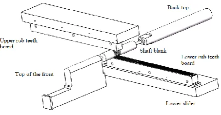
[image:2.595.185.412.630.748.2]The working principle of spline shaft cold roll forming is shown in figure 1. In the process of teeth, the two rub teeth board (rack die) move in synchronised with each other. Rub teeth board is fixed in each slider, and the workpiece is placed on the top between the two boards. The contact between rub teeth and shaft blank drives the shaft blank to rotate around the top, and the workpiece is pressed after rolling. The outer surface extrudes a series of grooves and projections. After the workpiece is rotated several revolutions, the required spline is formed to complete the cold forming process.
Figure 1. Schematic of cold roll forming.
forming and seceding. The two parts of the rub teeth boards are exactly the same when the number of splines is even, and the two pieces are staggered by half of the pitch when the number of splines is odd.
Modeling and Simulation Results
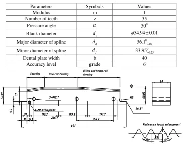
[image:3.595.116.481.197.489.2]The relevant parameters of spline and the corresponding rack die used in the simulating example are shown in table 1 and figure 2 respectively.
Table 1. Basic parameters of spline.
Parameters Symbols Values
Modulus m 1
Number of teeth z 35
Pressure angle 0
30
Blank diameter dz 34.94 0.01
Major diameter of spline da 0
0.16 36.1
Minor diameter of spline df
0 0.25
33.95
Dental plate width b 40
Accuracy level grade 6
Figure 2. Structure diagram of rack die.
The Establishment of Cold Forming Simulation Model
Figure 3. Simplified axial constrain mold and blank.
[image:4.595.139.454.293.382.2]Figure 4 shows the initial position of simulation model and both rack die of cold roll forming process. With this, the reasonable simplification of the model is established to ensure the following simulation process can run efficiently with acceptable accuracy.
Figure 4. The initial state of cold roll forming.
Preprocessing of Cold Roll Forming Simulation
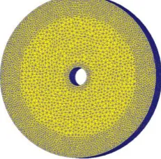
[image:4.595.239.355.522.636.2]By importing the previous stl format model, setting the blank material to 45 steel and rigid body for the dies and boards, a new task is created in Deform-3D software. The outer cylindrical ring of the blank is mesh-subdivided since the main deformation occurred in this region during the forming process. The total number of division meshes is up to 123604, as shown in figure 5. The length of the smallest grid unit is set to 0.28mm which is determined by tesing to ensure the convergence of the solution process and ensure the authenticity and accuracy of the simulation.
Figure 5. Meshes of the blank.
The frition and lubrication between blank and rack die are affected by the thickness of the oil film, the surface quality of the blank and rack die, the pressure and the sliding speed [9]. In the process of cold rolling, all these factors are constantly changing. It is inaccurate to use the Coulomb friction and shear friction model to describe it. However, to obtain accurate friction performance, a large number of friction performance tests are required. Here according to the existing research results, set the friction type to Coulomb friction, and set the friction coefficient to 0.3.
Preview the simulation motion process and confirm that the database file has been generated and complete the preprocessing of simulation.
Cold Roll Forming Simulation Results
The results of the spline shape obtained by the software simulator are shown in figure 6. There is no fold phenomenon in the steps of the entire simulation process. That is, the situation that the mesh does not have a large-scale continuous folding or enterance to the interior of the metal. It also shows the feasibility of parameter setting in previous preprocessing.
[image:5.595.143.483.192.327.2](a)Overall outline of spline (b)Partial enlargement
Figure 6. Overall and partial enlarged outline of spline.
Metal Flow Rate Analysis
For predicting the shape and size of the deformed body, designing the processing parameters and mold and conducting the quality analysis [10], The flow rate of metal during cold rool forming is analyzed, as shown in figure 7.
(a) Metal flow rate (b)Flow rate partial enlargement
[image:5.595.107.473.431.701.2](c)Metal flow direction (d)Flow direction partial enlargement Figure 7. Velocity of metal flow.
Figure (c) shows that the metal flow direction inside the spline is the tangential direction of the circle in the process of cold roll forming, and rapid increasing in value and chaos in direction of the speed nearby the contact point are shown in figure (d).
Cold Roll Forming Process Analysis
Based on the simulation results of the above forming process, the following four phases of involute spline cold rolling are specifically analyzed.
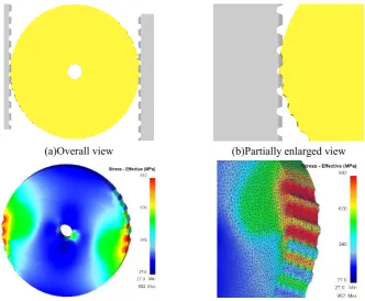
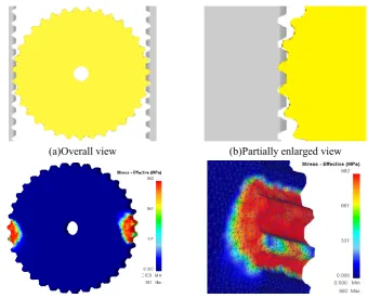
Biting Phase
The main task in this phase is to divide the teeth accurately where a series of shallow concave-convex surface on the blank shaft are revealed, as shown in figure 8(a) and (b). The condition of correct division is
min 1
arctan
Z
, whereZminis involute spline minimum number of teeth and is the
friction coefficient between workpiece and mold [11]. With appropriate bite angle and distance of rack die, feed of forming in biting phase gradually increases to ensure correct spline teeth profile to come into being in next phase.
(a)Overall view (b)Partially enlarged view
[image:6.595.130.463.309.583.2](c)Equivalent stress overall view (d)Equivalent stress magnification view
Figure 8. Phase of biting.
Rough Roll Forming Phase
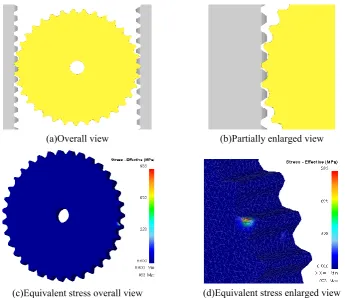
Figure 9 shows the rough roll forming phase of the spline, which further increases the degree of the groove and the projection on the basis of the deviding teeth. Materials of blank is furter extruded into teeth on rack die and the complete tooth shape gradually forms.
(a)Overall view (b)Partially enlarged view
[image:7.595.333.468.646.775.2](c)Equivalent stress overall view (d)Equivalent stress magnification view
Figure 9. Phase of rough roll forming.
Figures9 (c) and (d) are views of the equivalent stress at this phase. It can be seen that the areas with larger stress and strain are still mainly appeared in the cold roll region of the blank. Compared with the process of dividing teeth phase, the top part of the spline tooth is subjected to a greater stress due to the top surface of the shaft is in full contact with the bottom of the teeth on rack die. On the other hand, the stress at the center hole is much smaller than in the biting phase because with the constant shaping of the tooth in blank, the motion between the rack die and the spline shaft gradually approaches the gear motion of rack and pinion.
Fine Roll Forming Phase
Figure 10 shows the phase of the further shaping of the teeth profile and spline finish. At this phase, two surfaces of rack die are parallel to each other, and the mutual movement between the mold and shaft can be regarded as the gear motion of rack and pinion. However, the rack die still has a modification on the splines, and the tiny deformation generated in blank is mainly concentrated on the surface of the spline teeth which has a finishing effect.
[image:7.595.132.258.650.777.2](c)Equivalent stress overall view (d)Equivalent stress magnification view
Figure 10. Phase of fine roll forming.
Figures (c) and (d) show the overall and partial view of the equivalent stress at this phase. It can be seen that the stress is almost completely concentrated in the tooth, that is, only the teeth is modified.
[image:8.595.128.474.338.636.2]Seceding Phase
Figure 11 shows the seceding phase of spline cold roll forming. Due to the tooth profile angle on rack die (which is opposite direction of biting phase), the spline shaft does not press against the rack die at this phase. Spline disengaged from rack die with slight elastic recovery.
(a)Overall view (b)Partially enlarged view
(c)Equivalent stress overall view (d)Equivalent stress enlarged view
Figure 11. Phase of seceding.
Figures (c) and (d) are the overall and partial views of the equivalent stress at this phase. Stress at this phase is small but still exists. Shaft rotates along with rack die and seceding without pressure on the spine teeth.
Forming Force Analysis and Discussion
Figure 12. Schematic diagram of forming force.
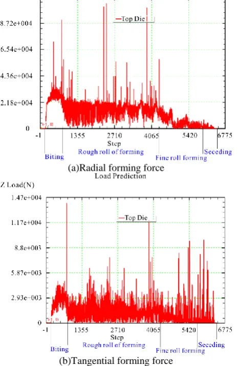
Figure 13 shows the simulation results of real-time changes in radial and tangential forces testing from one of the die plate.
(a)Radial forming force
(b)Tangential forming force
Figure 13. Radial force and tangential force in cold roll forming process.
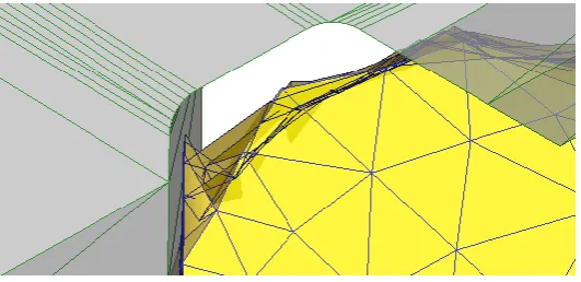
Figure 14. Grid reorganization.
It can be seen that the radial force and tangential force of the die boards are relatively large during the biting, rough roll forming phases, and there is still a certain amount of tangential force in the seceding phase. As discussed previously, in seceding phase spline shaft is still driven to rotate by die plates, and only no compression in the radial direction.
Conclusion
The time-course of spline cold roll forming process is investigated by numerical simulation in this paper. The correct teeth shape is obtained and the characteristics of metal flow in spline shaft is reviewed. Four phases which is biting, roughing, fining, and seceding in the spline cold rolling process are analyzed in detailed, and the stress and teeth shape change in each phase are listed and discussed. Through the simulation, the forming force and variation law of the spline cold rolling process are also obtained. The above studies can provide the reference and data supports for the optimization of the spline cold rolling process and the design of the cold forming equipment.
Acknowledgement
This research was financially supported by Research Program supported by the Anhui Province Science and Technology Major Project (16030901018).
References
[1] Pei Bang, Liu Shujie, Li Yao, et al: Comparison and Analysis of Commonly Used Involute Spline Standard at Home and Abroad. Journal of Mechanical Transmission, vol. 8, (2016) pp. 175-180.
[2] Wang Songjun, Chen Qiyun, Li Huijun, et al: Calculation of Press Fitting Force for Involute Spline Fit. Mechanical Research&Application, vol. 4, (2013) pp. 103-105.
[3] Liu Ruiqiu, Zhou Chunying: Key Techniques of Cold Rolling Numerical Simulation of Involutes Spline. Machine Building & Automation, vol.35, no.4, (2006) pp. 32-34, 39.
[4] Liu Ruiqiu: The Numerical Simulation of Cold Roll Forming of Involute Spline Based on ANSYS. New Technology & New Process, vol. 11, (2006) pp. 53-55.
[5] Wang Zhikui: Numerical simulation of spline in cold rolling based on DEFORM-3D. Modern Manufacturing Engineering, vol. 9, (2009) pp. 58-61.
[6] An Jianglong: Research on the Cold Extrusion Technology of Small Modulus Involute Spline Rolling and Rolling. New Technology&New Process, vol. 3, (2010) pp. 96-99.
[7] Zhang Li, Li Shengjun: Application of Deform in metal plastic forming. China Machine Press, (2010) pp. 28-29.
[9] Liu Ruiqiu: Numerical Simulation of Cold Roll Forming of Involute Spline (Master Thesis). Henan University of Science And Technology, China. (2005)
[10] Xie Lingling: Analyzing the Metal Moving and Designing the Dould in the Continuous Extrusion Extended Figuration (Master Thesis). Dalian Jiaotong University, China. (2005)