2018 International Conference on Computer Science and Software Engineering (CSSE 2018) ISBN: 978-1-60595-555-1
Research on Dynamical Control Algorithms
Rapid Validation Platform for Mobile Robots
Jinhua Ye, HongPeng Xu, Suzhen Yang and Jia Li
1
ABSTRACT
A realization method of semi-physical real-time simulation platform for mobile robot based on Quanser system is proposed in this paper. The robotic physical system is built by using the Quanser/IMDU module, the Matlab/Simulink and Quanser/QuaRC components are adopt to implement simulation system modeling and auto-matic generation of real-time control software. The Quanser/Q8 acquisition card is used as a communication medium for feedback data acquisition and real-time control of physical objects, so as to realize closed loop control of semi-physical simulation system. The platform can be used for fast verification of the complex control algorithm of mobile robot, and the effectiveness of the method is verified by the trajectory tracking control experiment of the semi-physical simulation system.
INTRODUCTION
Mobile robots have outstanding advantages in exploring unknown and dangerous areas that humans cannot reach. They have been widely used in various fields such as industry and agriculture, national defense and so on. And it is of great significance to study relevant technology. Motion control is one of the core research contents of mobile robots. In order to make the mobile robots more closer to perfect
speed tracking, the dynamic model of the system should be considered[1]. For the
control method verification, when the actual experiment is used, the relevant parameters of the dynamic system of the mobile robot are often not easy to be measured and adjust, which is not conducive to the rapid verification of the control
Ye Jinhua1, Yang Suzhen2, Xu Hongpeng1, Li Jia1
1
Fuzhou University, No. 2, Xue Yuan Road, New District, Fuzhou, Fujian, China.
2
method and prolongs the development cycle of the system. However, with pure numerical simulation, because of the inability to obtain the precise mathematical model of the system, some characteristics and parameters of the actual system are often ignored, and the designed controller is not available in the actual system. In order to solve the above problems, in this paper the concept of semi-physical simulation is adopt. The semi-physical simulation directly connects the control object to the simulation system, so it is also called Hardware-In-The-Loop (HIL) [2] simulation, and it is a real-time simulation of the actual process. Since the physical entity is put into the simulation loop, it has higher confidence degree than pure numerical simulation. And with the rational designing of physical entities and simulation systems, a more accurate system mode can be obtained, and the adjustment of the system parameters and the test of the complex control method are convenient. The verification of the results in the simulation process is intuitive and easy to operate.
In this paper, we combine Matlab/Simulink simulation software with Quanser's Q8 card, QuaRC development environment and Industrial Mechatronic Drives Unit (IMDU). Taking trajectory tracking control as an example, a dynamics control semi-physical simulation system for the (2, 0) type [3] wheeled mobile robot (WMR) is established. The experiment results show that the designed system satisfies the required performance indicators and meets the expected design requirements.
QUANSER HIL EXPERIMENTAL PLATFORM
Quanser's Q8 card [4] is a high-performance board that integrates real-time detection and control. It provides a rich hardware interface and complete software support with multiplexed high-speed A/D inputs and high-precision D/A output, encoder input, extended digital I/O and PWM output. The Q8 card uses a PCI interface to connect a computer and connects various external devices through a terminal inter-face card to form a closed-loop control structure.
the rest are free shafts. The use of single or multiple IMDU master units and their extensive modular components enables the construction of various complex industrial control systems with winding control, gap and friction compensation, and high-order coupling. IMDU provides motor torque (current) loop control and feedback and each shaft is equipped with a high-precision encoder. IMDU and Q8 terminal interface cards use standard data cables for connection.
ANALYSIS OF WMR DYNAMIC MODEL
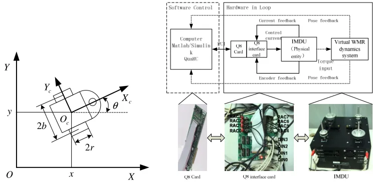
The WMR structure of study type (2, 0) and the spatial coordinate system are shown in Fig.1. It is composed of a trolley with two actuated wheels and an auxiliary front wheel (universal wheel). Through the different speed and steering control of the two driving wheels, various movement modes of the WMR can be realized. {XOY} is the world coordinate system, {X O Yc c c} is the local coordinate
system of WMR. The centroid Oc is the midpoint of the centerline of the two
rounds. The distance between the centers of the two wheels is 2b. The wheel radius
is r.
Define the position vector of WMR as T
[ , , ]x yθ
=
q , and the velocity vector of
two wheels is T
1 2 [ ,v v ] =
v , the control torque for both wheels is [ , ]T
r l
τ τ
=
τ . Due to the
nonholonomic constraints of each round, that satisfies the conditions of pure rolling
and no sliding. Its kinemics and dynamics equations can be described by [7]:
( )q
=
q S v (1)
( ) ( )
m d
+ + + =
Mv V v v F v τ τ (2)
Where
cos cos
( ) sin sin
cb cb
q cb cb
c c θ θ θ θ = − S ,
2 2 2 2 2 2
2 2 2 2 2 2
w
w
b c m c I I b c m c I
b c m c I b c m c I I
+ + −
=
− + +
M , m=mc+2mw
3
1 2 3
1 2
0 2 ( )
( )
2 ( ) 0
c m
c
bc m v v
bc m v v
−
=
− −
V v , 2
m
2 2
c w
I=I + m b + I ,c=r/ 2b,
T 1 2 [ , ] d = τd τd τ
is the external disturbance to both wheels. F v( )=[ ,F F1 2] is an un-modeled dynamic
item of the WMR dynamics system. Ic is the moment of inertia of output motor
shaft, Iw is the rotational inertia of the wheel. Im is the inertia of WMR around the
mass axis. mc and mware the mass of the body and the wheel that contain the motor
x O
y θ
c X c
Y
X Y
2b
2r c O
[image:4.612.110.482.84.269.2]
Figure 1. Structure of the WMR. Figure 2. Overall structure of the system.
PLATFORM HARDWARE AND SOFTWARE IMPLEMENTATION OF WMR SEMI-PHYSICAL SIMULATION SYSTEM
A. Overall Structure of the System
The overall structure of the WMR dynamics control semi-physical simulation system is shown in Figure 2. The system uses the IMDU to build the dynamics system of the WMR. The software control of the WMR trajectory tracking is implemented on Simulink and the real-time data exchange between the computer and the Q8 card is realized through the QuaRC. Simulink passes the motor drive current calculated during the real-time control of the WMR dynamic controller to the Q8 card, the Q8 card then outputs the drive current to the IMDU through the terminal interface card to achieve two-wheel torque control of the WMR. At the same time, the IMDU feeds back the actual drive current of the motor and the incremental encoder signal to the Q8 card through the terminal interface card. After being processed by the Q8 card, it is returned to the computer to realize closed loop dynamics trajectory tracking control of WMR.
B. Dynamic System Hardware Implementation
determine the specific value. The pressure value is defined as T, then the total quality of the WMR vehicle is
2 /
m= T g (3) In which g is the gravity acceleration.
C. Software system implementation
Taking the WMR dynamic trajectory tracking controller based on back-stepping design in [8] as an example, the implementation process of the software system is explained. The controller uses a control strategy that combines input-output nonlinear feedback linearization and adaptive sliding mode control.
Define the reference position as T
r r r [ , , ] r = x y θ
q . And the trajectory tracking
error of WMR in the X-axis and Y-axis directions is
[ ]T [ 1 2]T
r
r r
x−x y−y e e
= = = −
e q q (4)
Then the dynamic adaptive back-stepping sliding mode trajectory tracking controller is
( I) +
= −
τ H U f (5) 1( )
−
= −
U P u Pv (6)
1( 1 ) ˆ r ( sgn( ))
= − + − − + − − +
u k e δ c e PF q δ hσ λ σ (7)
1
= + +
σ k e e δ (8)
( T )T ˆ =µ
F σ P (9)
Where “+” represents the generalized inverse.
T -1
( )
=
H S MS SE, T -1 T
m
( ) ( )
= − −
1
f S MS S MSv V .
2 2× ∈
P R is a matrix of the first two rows in S q( ). σ is the sliding mode switching
function. Fˆ is the adaptive estimation.
1
=
δ c e, 2 2 1
× ∈
c R , 2 2×
∈
h、λ R are symmetric
positive definite constant matrix. µ is a positive constant.
Then the control torque τis converted to the drive current of the IMDU DC
motor. The conversion relationship is
(
)
/ c = k kg t
I τ (10)
Where kg is the reduction ratio of motor output to axle. kt is the motor torque constant.
c
I
I v
τ
U u
∫q q
q
1
−
P
P f1
( )
S q
d
τ
r
q
r
q
+
H
r
q e
e
( )
1 / k kgt
I
[image:6.612.109.483.83.216.2]U
Figure 3. IMDU module. Figure 4. Overall control structure of WMR trajectory tracking control.
When the system is running, the adaptive sliding mode controller module 3
obtains the position control deviation value e according to the IMDU feedback
speed value v and the reference trajectory qr, and based on formula (7) to calculate
the amount of intermediate control u. Input-output linearization (equation (6))
module 2 calculates the intermediate control input U required by the calculated
torque feedback module 1 based on the input u and feedback speedsv . The
reference input current Icof the WMR dynamic system module 4 is calculated in
combination with equations (5) and (10). Then, the current control deviation is obtained based on the current feedback value of the IMDU and the final control input UI of IMDU motor is obtained through the PI controller. The output of the
IMDU is the speed vof the two motor shafts, which is the WMR two wheels. Then
the change of WMR position is obtained by formula (1). Finally, the current position
q of the WMR is obtained by using integral operation.
The simulation model runs in the RTW environment. Firstly, The RTW and IMDU function blocks are initialized after the QuaRC is installed. Then in the Simulink parameter configuration options tab, select the “system target file” in Real-Time WorkShop as “quarc.windows.tlc” to complete the target language compiler configuration with QuaRC Win32 target system. Finally, the entire simulation model is compiled. During the compilation process, the automatically generated efficient real-time code is loaded into the QuaRC Win32 target system, realizing the real-time running of the control system software. Using the various monitoring modules in Simulink, the observation of experimental results can be performed intuitively, and it also facilitates the storage and management of experimental data.
EXPERIMENT
The hardware physical diagram of the entire system is shown in Figure 5.
WMR mechanical model parameters are r =0.0976m, b =0.19m, mc =24kg, mw
=0.8kg, Ic=8.625 kg⋅m2, Iw=0.0076kg⋅m2, Im =0.000007kg⋅m2, gear reduction
ratio is kg=3, motor torque constant iskt =0.0612 N·m/A. Under the semi-physical
simulation model, we can easily adjust various parameters and control modules to quickly obtain better control parameters. Adaptive backstepping sliding mode controller parameters is c1=diag(2,2), k1= diag(6,6), h=diag(10,10), λ=diag(2,2),ε1
=0.6,ε2 =0.8,µ =100. PI controller parameters arekI =0.4,kP =0.8. Circular arc
reference trajectory is
[
]
T0 cos( ) 0 sin( ) r = xc +R w tr yc +R w tr w tr
q .
The center of the circle is (xc0,yc0) =(4, 4), radiusR =2m, vr =w Rr , wr =2π
/5rad/s. System sampling period is ∆t= 0.001s. The starting position of the mobile
robot is q= [5m, 3.5m, π/4]T. Tracking results is as shown in figure 6, 7 and 8 respectively. It can be seen from the experimental results that the semi-physical simulation system better reflects the operating characteristics of the actual WMR system and the controller achieves a better control effect.
/ m
x
/m
[image:7.612.101.487.545.670.2]y
/ s
t
1/ m
e
2/ m
e
/ s t
/(
N
m
)
⋅
τ
/ (N m) B
τ ⋅
/ (N m) A
[image:8.612.135.459.87.203.2]τ ⋅
Figure 7. Tracking error. Figure 8. Control torque changes.
CONCLUSION
In order to facilitate the rapid verification of complex dynamic control methods of mobile robots, a semi-physical real-time simulation system based on Quanser/Q8 data acquisition card, Quanser/QuaRC development environment, Quanser/IMDU and Matlab/Simulink was proposed. The system uses the IMDU to simulate the dynamic system of the mobile robot. The Q8 card is used as the communication bridge between the simulation model and the physical model. Combined with QuaRC on Simulink, and through the C MEX S function to ensure the dynamic transmission of the system parameters and the efficient operation of the RTW simulation environment, the system software control is achieved. The real characteristics of the wheeled mobile robot are better reflected in this system. The parameter adjustment is convenient, the operation is simple and the verification process is intuitive. It facilitates the rapid construction and verification of various robot controllers. In addition, by increasing the number of IMDU master units, the semi-physical simulation of multiple robots can also be realized, and it can be extended to other multi degree of freedom robot systems.
ACKNOWLEDGMENT
This work was financially supported by the National Natural Science Fun of China (51575111, 51605093), Fujian Provincial Education Hall Youth Project (JAT-160877). Collaborative Innovation Center of High-End Equipment Manufacturing in Fujian.
2. Shahram K, Pilippe P, Shahrokn S. An HIL-based reconfigureable platform for design, implementation, and verification of electrical system digital controllers. IEEE Transactions on Industrial Electronnics, 2010, 57(4): 1226-1236.
3. Hwang C.L, Fang W.L. Global fuzzy adaptive hierarchical path tracking control of a mobile robot with experimental validation. IEEE Transactions On Fuzzy Systems, 2016, 3(24): 724-740. 4. Q8 Data Acquisition System User’s Guide Version 1.0. Canada Quanser Consulting Inc., 2003. 5. QuaRc 1.2 User Manual. Canada Quanser Consulting Inc., 2007.
6. Industrial Mechatronic Drives Unit (IMDU) User Mannual. Canada Quanser Consulting Inc., 2007.
7. Ye J.H, Yang S.Z, Jin X. Trajectory tracking control of WMR based on sliding mode disturbance observer with unknown skidding and slipping. Proceedings of the 2nd International Conference on Cybernetics, Robotics and Control. New York: IEEE, 2017: 18-22.