Abstract—Multiple-input multiple-output (MIMO) spatial multiplexing and beamforming are regarded as key technology enablers for the fifth-generation (5G) millimeter wave (mmWave) mobile radio services. Spatial multiplexing requires sufficiently separated and incoherent antenna array elements, while in the case of beamforming, the antenna array elements need to be coherent and closely spaced. Extensive 28-, 60-, and 73-GHz ultra-wideband propagation measurements in cities of New York City and Austin have indicated formation of two or more spatial lobes for the angles-of-departure and angles-of-arrival even for line-of-sight (LOS) transmission, which is an advantageous feature of mmWave channels, indicating that the transmitting and receiving array antenna elements can be co-located, thus enabling a single architecture for both spatial multiplexing and beamforming. In this paper a two-level beamforming architecture for uniform linear arrays is proposed that leverages the formation of these spatial lobes. The antenna array is composed of sub-arrays, and the impact of sub-array spacing on the spectral efficiency is investigated through simulations using a channel simulator named NYUSIM developed based on extensive measured data at mmWave frequencies. Simulation results indicate spectral efficiencies of 18.5-28.1 bits/s/Hz with a sub-array spacing of 16 wavelengths for an outdoor mmWave urban LOS channel. The spectral efficiencies obtained are for single-user (SU) MIMO transmission at the recently allocated 5G carrier frequencies in July 2016. The method and results in this paper are useful for designing antenna array architectures for 5G wireless systems.
Index Terms—Arrays, beamforming, 5G, mmWave, spatial multiplexing, SU-MIMO
Manuscript received March 16, 2017, revised July 10, 2017, accepted August 13, 2017. This work was supported in part by the Engineering and Physical Sciences Research Council under Grant EP/K031953/1. Copyright (c) 2017 IEEE. Personal use of this material is permitted. However, permission to use this material for any other purposes must be obtained from the IEEE by sending a request to [email protected].
Jaswinder Lota is with the University of East London, London UK (e-mail [email protected]) and is an honorary faculty member with the Department of
I.INTRODUCTION
pectrum allocation for fifth-generation (5G) cellular systems are classified by the 3rd Generation Partnership Project (3GPP) international cell phone standard body as being from 0.5 GHz up to 100 GHz [1]. The spectrum above 30 GHz is known as the millimetre wave (mmWave) band, with 28 GHz also being regarded as mmWave for its proximity to 30 GHz spectrum. The vast spectrum at frequencies above 28 GHz offers wide channel bandwidths that will support high peak data rates of several Gigabits per second. Such throughput speeds will be required for high-definition (HD) video, low latency content, and high data rate transfer between data centers and virtual interaction between people and machines [2]. Video continues to be the major application generator for mobile data traffic growth accounting for 51 percent of global mobile data traffic in 2012, and it is predicted to account for 75 percent of global mobile data traffic by 2020 [3]. The 28 GHz band is attractive as it enables mobility on mmWave due to 850 MHz of contiguous bandwidth in the United States, and has been a frequency of major focus for academic research and prototyping efforts; whereas the 38 GHz band [4] is particularly suited for ultra-high data rates and has initial agreement from the International Telecommunications Union (ITU) World Administration Conference as a global spectrum allocation. The 64-71 GHz spectrum would enable development of new innovative unlicensed applications and promote next generation high-speed wireless links with wider connectivity and higher throughput [5]. The Federal Communications Commission (FCC) in July 2016 allocated the 28 GHz, 37/39 GHz and 64-71 GHz frequencies both as licensed and unlicensed bands for the 5G mobile radio services (MRS) [5].
Multiple-input multiple-output (MIMO) has already been used in 4G long term evolution (LTE) cellular networks, and is regarded as one of the technologies likely to be adopted in 5G
Electronic & Electrical Engineering, University College London, London WC1E 7JE UK (e-mail: [email protected]). S. Sun and T. S. Rappaport are with NYU WIRELESS and Tandon School of Engineering, New York University, Brooklyn, NY 11201 USA (e-mail: [email protected]; [email protected]). Andreas Demosthenous is with the Electronic & Electrical Engineering Department, University College London, London WC1E 7JE UK (e-mail: [email protected]).
5G Uniform Linear Arrays with Beamforming
and Spatial Multiplexing at 28 GHz, 37 GHz, 64
GHz and 71 GHz for Outdoor Urban
Communication: A Two-Level Approach
Jaswinder Lota,
Senior Member, IEEE,
Shu Sun,
Student Member, IEEE,
Theodore S. Rappaport,
Fellow, IEEE,
Andreas Demosthenous,
Senior Member, IEEE
S
to increase peak data rates along with beamforming for low signal-to-noise ratio (SNR) scenarios such as cell edge users [6]-[8]. Beamforming approaches that are suitable for mmWave frequencies can be broadly classified as analog, hybrid analog-digital, and low resolution analog-digital, each having specific implications for deployment in mmWave MIMO channels. Analog beamforming requires analog phase shifters which are adaptively adjusted to vary the phases of antenna elements, thereby increasing the antenna gain to counter the path loss in line-of-sight (LOS) and non-line-of-sight (NLOS) mmWave propagation [9]. Phase shifters can be active elements, which suffer phase-shifter loss, noise and nonlinearity, or they can be passive, where passive phase shifters have the advantage of low power consumption and reduced nonlinearity, but incur more insertion loss and occupy more area [10]. Analog beamforming is employed with beam training algorithms and acquiring the channel state information (CSI). Hybrid (analog-digital) beamforming requires either precoding or combining techniques both in the baseband and radio-frequency (RF) level [11]-[14] and can be designed through different approaches using phase shifters [15], switches [16] and lenses [17]. Hybrid beamforming can be employed by having a group of elements connected to one RF chain or an array of sub-arrays, where each sub-array has several interconnected antenna elements but its own RF chain.
MmWave MIMO transmission requires multiple antenna elements to provide beamforming gain to compensate for higher path loss on account of mmWave incurring higher attenuation in the first meter of propagation due to Friis law [18]. Making a highly directive antenna with small beamwidths, steerable over large angle ranges for the angle of arrival (AOA) at the receiver (Rx), would ensure a high gain. This adaptive beamforming requires multiple elements with high coherence to enable beamforming and with beam steering that requires co-polarized antenna elements closely spaced typically at 𝜆𝜆2 , where 𝜆𝜆 is the carrier wavelength. MIMO transmission requires spatial multiplexing (SM) which is ensured by separate spatial paths of parallel transmissions, which mandates a contrary requirement of ensuring that there is no coherence between antenna elements transmitting parallel data streams simultaneously, i.e. antenna elements that are either cross-polarized, orthogonal in spatial beam patterns, and/or relatively spaced far apart [19]. This requires an antenna element spacing of greater than 𝜆𝜆2 which reduces coherence among antenna elements, but leads to formation of grating and quantization lobes which reduce the available angle range for beam steering. Continuous phase shifting requirements from 0° to 360° are expensive and typically not used in practice. Phase shifts are digitally controlled by realizing discrete phase shifts which causes quantization phase error leading to formation of quantization lobes, which occur at the grating lobe angles during beam steering. Meeting both MIMO and beam steering requirements simultaneously in a single architecture is challenging. In this paper these are explained followed by an architecture that addresses these challenges. Simulations are undertaken with a mmWave channel simulator developed by New York University (NYU) from extensive field data, NYUSIM v1.5, to characterize the MIMO channel conditions at the recently allocated FCC 5G frequencies of 28, 37/39, and
64-71 GHz. Section II details current limitations in single-user (SU)-MIMO with beam steering along with the proposed hybrid architecture. The mmWave MIMO channel model is described in Section III, based on a 3D statistical spatial channel model (SSCM) along with how the channel coefficients are obtained for the MIMO channel matrix H. The section details degrees of freedom (DOFs) and channel condition number for H that quantify SM required for MIMO transmission. Section IV details the uniform linear array (ULA) element design and the array pattern, formation of the grating and quantization lobes. The channel condition number and spectral efficiency values obtained from simulations for various sub-array spacings are given in Section V, followed by conclusions in Section VI.
II. TWO-LEVEL HYBRID BEAMFORMING WITH SPATIAL MULTIPLEXING
A. Current Limitations in SU-MIMO
In the case of SU-MIMO, more than one spatial stream is exchanged between two arrays. Due to the multipath sparsity, the channel propagation matrix can be near-singular and conventional MIMO capacity will degrade significantly. The antenna spacing and array orientation can significantly affect the system performance [19], [20]. SU-MIMO capacity for a full digital mmWave array has been studied in [21] for LOS and in [20] for a two-path channel. When the LOS-path is dominant, multiplexing gain is largely limited to the gain achievable by LOS-MIMO, which relies on careful placement of Tx and Rx antennas. For a full digital array, the LOS-MIMO capacity, which can be achieved at the Rayleigh distance, depends on the orientation of Tx and Rx arrays, their distance R, the element spacing and the number of antenna elements. The Rayleigh distance criterion leads to a full-rank and orthogonal MIMO channel matrix, but generally requires impractically large antenna space and array size. Nevertheless, results in [20]–[27] indicated that in principle it is possible to achieve the maximum multiplexing gain in mmWave MIMO channels with LOS transmissions by carefully designing the geometrical distribution of the antennas at both link ends. Using aligned ULAs at both ends showed that the channel vectors experienced by different Tx/Rx antennas can be mutually orthogonal if the antenna spacings and the end-to-end distance satisfy the Rayleigh distance criterion. This approach of Rayleigh distance criterion, however, relies on careful placement of Tx and Rx and is not practical for outdoor urban communication, which may require varying distances between Tx and Rx based on the different requirements of cell design and geometry. For a setup with a carrier frequency of 38 GHz, two parallel ULAs with 16 elements, and R = 500 meters, achieving system capacity requires an element spacing of about 0.5 m (~ 63 wavelengths). In [21], system throughput is examined for arrays with closer element space. It is shown that the maximum distance to support multiplexing communications over LOS-MIMO channels is mainly determined by the product of the aperture sizes of the Tx and Rx antenna arrays, instead of the numbers of antennas at both ends. For communication distance in the order of kilometers, the multiplexing gain is limited to 4, even for a large array size of 5 m.
constrained to a limited beam steering angle due to formation of grating lobes [23]-[27], thus the optimal spacing between the antenna elements for the Rayleigh distance criterion may not be optimal for beam steering. Therefore an antenna configuration based on the Rayleigh distance criterion would be severely constrained in terms of the beam steering angle.
In view of the challenging requirements for SU-MIMO, extensive investigation of the state-of-the-art hybrid precoding techniques is undertaken as reported in [28]-[43]. This indicates that most of the existing work details performance of architectures that are applicable to multiple-user MIMO (MU-MIMO). In these cases, Rx antenna arrays can be separated by considerable distances as these are for multiple users which can ensure sufficient spatial separation that enables SM. Similar Rx antenna array separations are not feasible for SU-MIMO on a single mobile user equipment. Secondly, SM in mmWave propagation depends on both the channel and antenna properties. Antenna properties such as the radiation pattern, the sub-array spacing and orientation are intrinsic to implementing the ULA design which must be considered for obtaining the channel coefficients. These parameters are crucial to analysis of SM but also for the beamforming constraints such as formation of quantization and grating lobes in relation to the ULA architecture. Some analyses for SU-MIMO hybrid precoding are given in [28], [30], [36], [42], [43] but parameters assumed are for NLOS mmWave channels. Also, previous work did not systematically study the effects of sub-array spacing in mmWave for SU-MIMO, or formation of quantization and grating lobes which is an area of current research [19], [44]. Having multiple sub-arrays reduces hardware complexity at the expense of less overall array flexibility for beam scanning and MIMO which needs careful analysis. Overall, in the existing approaches, SU-MIMO is a less attractive option in mmWave cellular systems due to limited multiplexing gain and dependency on the distance relationship. The main motivation for employing hybrid precoding in mmWave MIMO is for reducing the hardware resources. Employing a specific hybrid precoding technique or comparison of the existing hybrid precoding techniques such as for optimizing the hardware resources in mmWave MIMO is not the focus of this paper. Rather, our paper provides an alternative approach to the Rayleigh distance criterion that enables SM for SU-MIMO in LOS mmWave channels. Encouraging results for up to 500m Tx-Rx separation distance are reported which are practical to implement for urban outdoor mmWave cell sizes. The proposed architecture is not constrained to any beam steering angle due to formation of grating lobes. As the proposed architecture is based on sub-arrays, a suitable hybrid precoder can be accordingly employed to offer reduction in hardware resources.
Furthermore this novel approach leverages the unique characteristic of mmWave propagation which is formation of one or more spatial-lobes (SLs) even in LOS channels due to a rich scattering environment, which is not reported earlier in the context of enabling SM for SU-MIMO in LOS mmWave channels. The antenna elements can be co-located averting the limitation of space requirements as SM is ensured due to different angles of departure (AODs) and AOAs of the SLs even in LOS propagation. The existing 3GPP channel models [1][45] do not include the effects of directional local scattering at the Tx and Rx in an outdoor urban environment for mmWave
propagation, yet real-world measurements in New York City show the existence of directional propagation in urban environments, leading to the formation of SLs [2], [46], [47]. SLs conveniently represent the mmWave radio channel because they implicitly account for directionality, a key differentiator of future wireless cellular and mobile systems operating in the mmWave spectrum compared with today’s ultra-high frequency (UHF) and microwave systems.
B. System-Level Architecture
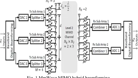
In order to meet the contradictory requirements of beamforming which requires co-polarized closely spaced antenna elements typically at 𝜆𝜆2 with high coherence, and SM which requires no coherence between antenna elements to ensure simultaneous separate parallel data streams [19], a two-level (2L) hybrid beamforming architecture is proposed as illustrated in Fig. 1. The architecture follows a 2L hierarchy wherein at level 1 (L1) each sub-array at the Tx and Rx is employed to adaptively form highly directive beams to provide beamforming gain. Each sub-array is an analog array consisting of antennas connected with adjustable phase shifters in the RF chain. Each sub-array is connected to a baseband processor via a digital-to-analog converter (DAC) in the Tx or an ADC in the Rx. Level 2 (L2) is the resulting MIMO system that enables SM of these beams to increase channel capacity by supporting simultaneous parallel data transfer based on the selected spatial directions of the sub-arrays formed from L1. A similar approach has been proposed in [26] for E-band (70-95 GHz) and employed for SM for a 60 GHz indoor link [27]. In [26], simulated values indicate higher spectral efficiency as the physical spacing of the sub-array antennas is increased, where sub-arrays with highly directive pencil beams are employed in telescopic dish configurations. However, these highly directional sub-array antennas are constrained for beam steering due to formation of grating lobes at 10° off boresight, since the increase in sub-array separation reduces the available angular sector for which grating lobes do not occur. One can increase the sub-array spacing to increase the number of SM paths but this leads to formation of the grating lobes, severely restricting the beam steering angle. In [27], analysis was restricted to only MIMO SM and no beamforming was employed in an indoor environment. The 2L approach presented in this paper can combine SM with beamforming for ULAs to enable prototype development of handsets and point-to-point Txs/Rxs in outdoor LOS or NLOS urban environments for SU-MIMO.
Tx super-array consists of 12 elements (4 from each of the 3 sub-arrays) and the Rx super-array consists of 8 elements (4 from each of the 2 sub-arrays). The element spacing at L1, i.e. within each sub-array is given by 𝑑𝑑𝑆𝑆𝐴𝐴, which remains 𝜆𝜆2, while the distance 𝑑𝑑 is the separation of the sub-arrays, which are considered to be single elements for MIMO at L2.
Fig. 1 MmWave MIMO hybrid beamforming.
The proposed architecture enables generating the channel coefficients based on the number of NT, NRand the half-power
beamwidth (HPBW) for a single beam that is transmitted through the channel. At L2 accordingly the individual number of sub-array elements M are reflected through the HPBW for a single beam. It is worth noting that the HPBW is for the entire antenna array i.e. the super-array. In case of low SNR conditions the architecture enables beamforming via the antenna elements within each sub-array, such that one or more weights are generated to be applied to the individual ULA antenna element signals. During normal/high SNR conditions MIMO SM is carried out using sub-arrays, with each sub-array treated as a single radiating element in a MIMO super-array system that sends different data streams through each sub-array [19]. The antenna element spacing can be interleaved or localised among the sub-arrays, the later as in Fig. 1 offers smaller grating lobes, larger LOS-MIMO capacity of a given array size and is practical for hardware implementation as compared to the former [44]. In case of low SNR during beamforming all the elements in the entire super-array transmit the same symbol to compensate for the high path loss with the beamforming gain. While in case of normal or high SNR conditions for meeting the requirements of high data transfer with MIMO, the three transmitting sub-arrays in Fig.1 would transmit two different symbols for SM. Since the
antenna element spacing does not change during both modes of transmission this circumvents formation of grating /quantization lobes during beamsteering
Various super-array configurations are possible for the ULA architecture in Fig. 1. Some of the configurations presented in this paper are detailed in Table I, where 𝑁𝑁 is the total number of antenna elements at L1, 𝐶𝐶𝑀𝑀𝑀𝑀 is the array configuration with 𝑥𝑥denoting the number of elements in each sub-array, and 𝐿𝐿𝑦𝑦 the entire array length considering all sub-arrays in cm at 𝑦𝑦 carrier frequency in GHz. If the lateral separation 𝑑𝑑 between the sub-arrays is increased, with a view to reduce correlation between sub-arrays, the visible region for beam steering of the super-array (composed of sub-super-arrays) decreases, due to formation of grating and quantization lobes.
III.MMWAVE CHANNEL MODEL
A. 3D Statistical Spatial Channel Model
The MIMO channel model is based on a 3D SSCM for urban LOS and NLOS channels developed from extensive 28-, 60-, and 73-GHz ultra-wideband propagation measurements in cities of New York City and Austin [46], [47]. The model generates channel impulse responses (CIRs) that match measured field data at wide range of distances and over local areas based on the time cluster–spatial lobe (TCSL) modeling framework. The approach extends the 3GPP model through directional root mean square (RMS) lobe angular spreads (ASs) and is consistent with the 3GPP modelling framework. Based on the 3D statistical channel model in [46], [47], a MATLAB-based statistical simulator, NYUSIM v1.5, has been developed by NYU [48], [49] that can generate 3D AOD and AOA power spectra along with omnidirectional and directional power delay profiles (PDPs) that match measured field results. 3GPP has unrealistically large number of strong eigenvalues which are not found in measured mmWave channels. In order to realistically quantify performance, NYUSIM v1.5 is employed in this paper for simulating the MIMO channel as the simulator is built from field data which gives more realistic results [50].
TABLE I
SUPER-ARRAY CONFIGURATIONS FOR FIG. 1 WITH LENGTHS IN CM.
[image:4.612.52.294.133.270.2]
B. Parameters and Antenna Properties.
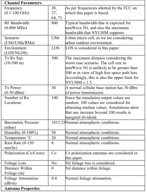
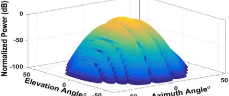
[image:5.612.48.291.411.729.2]The simulator settings for the channel parameters and the antenna properties employed for simulations in this paper are listed in Table II. UMi, UMa and RMa denote urban microcell, urban macrocell and rural macrocell settings, respectively. Co/Cross is the polarization between the Tx and Rx antenna arrays. Typical values for the barometric pressure, humidity, temperature, rain rate and foliage attenuation have been used with nil foliage loss. For the antenna properties, ULAs have been considered at the Tx and Rx with a variable antenna spacing d (i.e. the L2 sub-array spacing), the number of transmitting antenna elements (varying from 2 to 8, which is the number of sub-arrays at L2) is 𝑁𝑁𝑇𝑇, and number of receiving sub-arrays is 𝑁𝑁𝑅𝑅. The Tx and Rx azimuth and elevation HPBWs are for the super-array at L2. In Section IV, the ULA antenna element has been designed with CST MICROWAVE STUDIO® and array patterns developed using MATLAB R2016a® generating HPBW input parameters for NYUSIM v1.5. For various configurations in Table I, the maximum azimuth HPBW is 12.6° (±6.3°) and elevation HPBW is 88° (±44°). With an increase in the number of sub-array elements, the azimuth HPBW becomes less than6.3° (±3.3°) and is taken as 7° which is the lower limit in NYUSIM v1.5. The elevation HPBW remains constant and is taken as 45°, the upper limit in NYUSIM v1.5. A larger elevation HPBW would not affect the SM since for horizontal ULAs the azimuth HPBW is more critical.
TABLE II
NYUSIM V1.5 SIMULATION SETTINGS USED IN THIS STUDY. Channel Parameters
Frequency
(0.1-100 GHz) 28, 37, 64, 71
As per frequencies allotted by the FCC on which this paper is based.
RF Bandwidth
(0-800 MHz) 800 Typical bandwidth that is expected for mmWave 5G, and also the maximum bandwidth that NYUSIM supports Scenario
(UMi/UMa/RMa) UMi Urban micro cell, as we are considering urban outdoor environment. Environment
(LOS/NLOS) LOS LOS is considered in this paper. Tx Rx Sep.
(10-500 m) 500 The maximum distance considering the worst case scenario. The cell size in mmWave 5G is unlikely to be greater than 500 m in view of high free space path loss. Accordingly, this is also the upper limit for NYUSIM v.1.5.
Tx Power
(0-30 dBm) 30 A normal cellular base station has 30 dBm of power transmission. Number of Rx
Locations 100 Since the simulation output values are random, 100 values are considered for obtaining median values. Simulations show that any increase beyond 100 results is marginal dividend.
Barometric Pressure
(mbar) 1013.25 Normal atmospheric conditions. Humidity (0-100%) 50 Normal atmospheric conditions. Temperature °C 20 Normal atmospheric conditions. Rain Rate (0-150
mm/hr) 8 Normal atmospheric conditions. Polarization (Co/Cross) Co Co polarization antennas are considered in
this paper.
Foliage Loss No Nil foliage loss is considered. Distance Within
Foliage (m) 0 Nil distance within foliage. Foliage Attenuation
(dB/m) 0.4 Normal foliage attenuation. Antenna Properties
Tx Array Type
(ULA/URA) ULA Horizontal ULAs are considered in this paper. Rx Array Type
(ULA/URA) ULA Horizontal ULAs are considered in this paper. No. of Tx elements
(sub-arrays) NT Relevant Parameter. No. of Rx elements
(sub-arrays) NR Relevant Parameter. Tx Antenna (sub-array)
Spacing (in λ, 0.1-100) d Relevant Parameter. Rx Antenna (sub-array)
Spacing (in λ, 0.1-100) d Relevant Parameter. Tx Antenna
(Super-Array) Azimuth HPBW (7°-360°)
12.6,
7 In Section IV, the ULA antenna element has been designed with CST MICROWAVE STUDIO® and array patterns developed using MATLAB R2016a® generating HPBW input parameters for NYUSIM v1.5. Eqs. (5)-(9) in Section IV are used to plot array pattern in Fig 6 from which the HPBW for azimuth and elevation values are extracted and detailed in TABLE II. This happens to be 12.6 degrees (azimuth) and 45 degrees (elevation) for the configuration with lowest number of array elements CM4 and are
taken as such for simulation. For CM8, the
number of elements is doubled, accordingly the HPBW is half of 12.6 degrees which is 6.3 degrees (azimuth) and 45 degrees (elevation-does not change as the number of elements are changing in azimuth only). But the NYUSIM v1.5 has a lower limit of HPBWs of 7 degrees for azimuth and elevation. Thus for simulations in this paper, an azimuth of 7 degrees is taken. SM gets worse as the HPBW increases, thus the NYUSIM v1.5 gives a worst case scenario which can be accepted; as 6.3-degree azimuth HPBW is expected to achieve even higher spectral efficiencies. The narrower the azimuth beam, the higher the SM gain. Accordingly, CM16 azimuth HPBW is 3.13
degrees and for CM32 this decreases to 1.565
degrees. HPBW is taken as the lower bound in NYUSIM 1.5 which is 7 degrees. Accordingly, even better spectral efficiencies are expected for these configurations as we are assuming worse HPBW values than expected. Tx Antenna (Super-Array) Elevation HPBW (7°-45°) 45
Rx Antenna Azimuth HPBW (7°-360°) 12.6, 7 Rx Antenna Elevation HPBW (7°-45°) 45
C. MIMO Channel Matrix Degrees of Freedom
Multi-carrier transmission is one of the technologies being considered for mmWave. Considering orthogonal frequency division multiplexing (OFDM) transmission, each resolvable multipath component contributes to the MIMO channel coefficients for an OFDM sub-carrier. Assuming ULAs at both the Tx and Rx, the channel coefficient is given by [51]:
ℎ𝑚𝑚,𝑘𝑘(𝑓𝑓) =
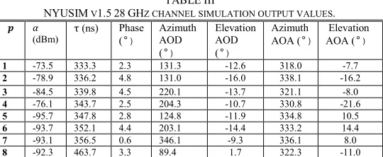
TABLE III
NYUSIM V1.5 28 GHZ CHANNEL SIMULATION OUTPUT VALUES. 𝒑𝒑 𝛼𝛼
(dBm) τ (ns) Phase (°) Azimuth AOD
(°)
Elevation AOD
(°)
Azimuth
AOA (°) Elevation AOA (°)
1 -73.5 333.3 2.3 131.3 -12.6 318.0 -7.7 2 -78.9 336.2 4.8 131.0 -16.0 338.1 -16.2 3 -84.5 339.8 4.5 220.1 -13.7 321.1 -8.0 4 -76.1 343.7 2.5 204.3 -10.7 330.8 -21.6 5 -95.7 347.8 2.8 124.8 -11.9 334.8 10.5 6 -93.7 352.1 4.4 203.1 -14.4 333.2 14.4 7 -93.1 356.5 0.6 346.1 -9.3 336.1 8.0 8 -92.3 463.7 3.3 89.4 1.7 322.3 -11.0
The channel matrix H is formed by the entries of channel coefficients generated in (2), assuming the frequency interval between adjacent sub-carriers is 10 MHz, which corresponds to 800 MHz/10 MHz + 1 = 81 sub-carriers, as 800 MHz is the RF bandwidth in the simulation settings in Table II. For the channel matrix H, one can quantify the multiplexing capacity. With probability 1 the rank of the random matrix H is given by [52]:
rank(H) =min {no. of independent non-zero rows, no. of independent non-zero columns} (2) This yields the DOFs available in the MIMO channel. The number of independent non-zero rows and columns depends on the amount of scattering, reflection and the length 𝐿𝐿𝑦𝑦 of the Tx and Rx arrays. The more scatterers and reflectors there are, the larger the number of non-zero entries in H and the larger the DOF. Increasing 𝐿𝐿𝑦𝑦 increases the array aperture allowing for higher resolution of more paths resulting in non-zero entries of H. The AS for the AOD and AOA relate to the spatial selectivity of the channel, where it has been shown that directionality of the mmWave channel is noticeable and repeatable, and can be expressed in terms of spatial lobes that have a particular azimuth (AZ) and elevation (EL) angle spread [46]. The coherence distance across an antenna manifold provides a measure of maximum spatial separation over which multipath components of a transmitted signal have strong correlation and is inversely proportionate to the AS. MIMO channels even with co-located Tx and Rx antennas with reflectors and scatterers far away can also provide a DOF gain. For a channel where signals depart at the Tx array of length 𝐿𝐿𝑦𝑦 and arrive at the Rx array with a length of 𝐿𝐿𝑦𝑦 in distinct SLs as is the case for mmWave channels, with AS of the 𝑘𝑘th SL as Θ𝑡𝑡𝑘𝑘 and Θ𝑟𝑟𝑘𝑘 for the AOD and AOA respectively, the DOF is given by [53]:
𝑚𝑚𝑚𝑚𝑚𝑚 �∑ �𝐿𝐿𝑦𝑦⌊𝜃𝜃𝑡𝑡𝑘𝑘⌋�𝑘𝑘 ,∑ �𝐿𝐿𝑦𝑦⌊𝜃𝜃𝑟𝑟𝑘𝑘⌋�𝑘𝑘 �
(3)
MmWave propagation due to comparatively smaller 𝜆𝜆 as compared to current MRS frequencies such as those used in LTE undergoes weaker diffraction due to reduced Fresnel zones, larger penetration loss and higher scattering. The diffused scattering leads the signal to arrive at the Rx in distinct SLs. Measurements undertaken for the 28 GHz NLOS channel in urban environments indicate a mean number of 1.6 SLs for both AOD and AOA. For the 73 GHz NLOS the mean values are 1.5 and 2.5 for the AOD and AOA respectively. More AOA SLs at 73 GHz arise from more prominent local scattering than at 28 GHz [46], likely due to the more thorough scanning in azimuth and elevation [47]. Measurements in [2], [46], [47] also indicate that for the LOS scenario, the mean number of AOD SLs was higher than the NLOS case at 28 and73 GHz, suggesting that multipath signals can reach the Rx from more departing angles even in LOS cases; The mean number of AOA SLs for LOS and NLOS was found comparable indicating that both spatial environments appear similar to the Rx. SLs due to local scattering in mmWave account for directionality and are a key differentiator for mmWave MRS as compared to existing MRS such as LTE. The cumulative density function (CDF) plot for ∑ Θ𝑡𝑡𝑘𝑘𝑘𝑘 and
∑ Θ𝑟𝑟𝑘𝑘𝑘𝑘 in Fig. 2 obtained from 100 random channel
[image:6.612.35.305.55.166.2]realizations in the LOS scenario with NYUSIM v1.5 indicate higher values for the 28 GHz band as compared to an 800 MHz LTE channel implying a higher DOF for similar array lengths.
Fig. 2 CDF for AOD and AOA AS at 28 GHz and 800 MHz.
C. MIMO Channel Matrix Condition Number
linear Rxs in MIMO systems. Performance of linear detectors such as zero-forcing (ZF), maximum-likelihood (ML) and minimum mean square error (MMSE) detectors has been investigated indicating strong dependence of the detector performance on the channel condition number [64]-[70]. The channel condition number is also adopted to formulate novel spectrum sensing algorithms in cognitive radio applications [71]-[73] for MIMO systems.
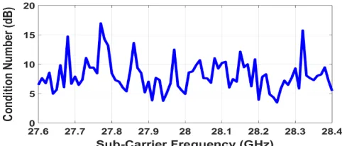
[image:7.612.326.567.55.158.2]A MIMO system can provide both SM and diversity gain with adaptive switching. Such adaptive switching schemes can switch between SM and diversity for an optimal performance based on various parameters of the channel. The channel condition number is one such parameter that is employed as the switching criteria [64], [65], [74]. In [64] probability of SM versus diversity is given as a function of the number of antennas for a MIMO Rayleigh fading channel based on distribution of the channel condition number. The system proposed in [65] chooses either BLAST or STBC based on the instantaneous channel condition number. Furthermore, channel condition number is employed in the industry to analyze potential causes for throughput issues [75] and is an important design parameter used in 3GPP standards such as for the LTE [76]. For wireless system designers, this forms an important baseline reference for characterizing the MIMO channel for designing Rxs in 5G mmWave systems. Formation of higher number of SLs in mmWave even for LOS scenarios implicitly account for directionality which ensure that the channel matrix H is well-conditioned when compared to existing sub mmWave mobile radio channels. Typical values of channel condition numbers for LTE range from 5-15 dB as measured by 3GPP in [76]; a similar method is employed in this paper for evaluating the channel condition numbers. The magnitudes of the six channel coefficients for the 2x3 L2 MIMO channel matrix H in Fig. 1 are depicted in Fig. 3. ULAs are applied during the generation of H, and the separation distance of sub-arrays is half-wavelength. Fig.3 shows that the transmitted wideband signal undergoes frequency-selective fading, and the fading magnitude varies for different Tx-Rx antenna sub-array combinations. Although the multipaths are not rich in outdoor mmWave channels, the phases of the multipaths change over sub-carriers, which lead to different channel coefficients and hence different channel matrices over sub-carriers. Therefore, the channel condition numbers over different sub-carriers vary significantly. The corresponding channel condition number for each sub-carrier is plotted in Fig. 4, which clearly shows the fluctuation of the channel condition number over sub-carriers, where the discrepancy can exceed 12 dB.
Fig. 3 MIMO channel matrix coefficient magnitudes for OFDM.
Fig. 4 Condition number of the channel matrix for OFDM sub-carriers with three transmit sub-arrays and two receive sub-arrays.
IV. ULA ARRAY PATTERN
A. Sub-Array Antenna Element
[image:7.612.380.496.418.534.2]The azimuth and elevation sub-array radiation pattern would depend on 𝑀𝑀 in each sub-array and their individual element radiation pattern (𝐸𝐸(𝜃𝜃)). A typical sub-array element can be designed as a rectangular or circular patch antenna. Both circular and rectangular patches have similar gain, beam position and efficiency. The circular patch however offers slightly narrower beamwidth and smaller physical area. Circular patches have increasingly become popular as they can offer increased levels of linear polarisation, frequency agility, viable mechanical properties and stability [77]-[79]. A circular pin-fed antenna patch is employed in this paper and its design parameters are given in Fig. 5 [80], where 𝐷𝐷, 𝑆𝑆𝜋𝜋, 𝑅𝑅, 𝐻𝐻, 𝜖𝜖𝑟𝑟 and𝑡𝑡𝑡𝑡𝑚𝑚𝑡𝑡 are the patch diameter, feed offset, feed pin radius, substrate height, relative permittivity and loss tangent due to the substrate medium respectively.
Fig. 5 Sub-array patch antenna element. The patch antenna element was modelled using CST MICROWAVE STUDIO® Antenna Magus for a frequency 𝑓𝑓𝑐𝑐 as listed in Table IV.
TABLE IV
SUB-ARRAY ELEMENT DESIGN PARAMETERS.
Parameter Value
𝑓𝑓𝑐𝑐 (GHz) 28 37
𝐷𝐷 (mm) 4.265 3.277
𝑆𝑆𝜋𝜋 (µm) 477.1 361.0
𝑅𝑅 (µm) 28.39 21.48
𝐻𝐻 (µm) 227.1 171.9
𝜖𝜖𝑟𝑟 2 2
[image:7.612.46.279.605.706.2]GHz and 37 GHz respectively. The dominant mode is 𝑇𝑇𝑀𝑀11 and the radiation pattern is a single lobe with maximum in the direction normal to the plane of the antenna. Elements with similar characteristics can be designed at 64 GHz and 71 GHz.
B. Super-Array Element Spacing and Grating Lobes
The spatial response of a ULA with 𝑁𝑁 array elements, with element amplitude and spacing of 𝐴𝐴𝑁𝑁 and 𝑡𝑡, and signal incident to the ULA at an angle 𝜃𝜃 is given by the array factor
(𝐴𝐴𝐴𝐴):
𝐴𝐴𝐴𝐴=� 𝐴𝐴𝑚𝑚𝑒𝑒𝑗𝑗2𝜋𝜋𝜆𝜆 𝛿𝛿𝑚𝑚𝑚𝑚𝑚𝑚𝛿𝛿 𝑁𝑁
𝑚𝑚=1
(4)
Assuming identical 𝐸𝐸(𝜃𝜃)for each element in ULA, the array pattern (𝐴𝐴(𝜃𝜃)) is then given by the pattern multiplication: 𝐴𝐴(θ) = E(θ). A𝐴𝐴 (5)
In the case that 𝑁𝑁 elements are divided into 𝑁𝑁𝑇𝑇 sub-arrays where elements per sub-array is 𝑀𝑀=𝑁𝑁𝑁𝑁
𝑇𝑇, then the sub-array pattern 𝐴𝐴(𝜃𝜃)𝑆𝑆𝑆𝑆𝑆𝑆𝐴𝐴 is accordingly given by:
𝐴𝐴(𝜃𝜃)𝑆𝑆𝑆𝑆𝑆𝑆𝐴𝐴=𝐸𝐸(𝜃𝜃).� 𝐴𝐴𝑚𝑚𝑒𝑒𝑗𝑗2𝜋𝜋𝜆𝜆 𝑑𝑑𝑆𝑆𝑆𝑆𝑚𝑚𝑚𝑚𝑚𝑚𝛿𝛿 𝑀𝑀
𝑚𝑚=1
=𝐸𝐸(𝜃𝜃).𝐴𝐴𝐴𝐴𝑆𝑆𝑆𝑆𝑆𝑆𝐴𝐴 (6) The array pattern of the ULA super array beamforming then can be obtained by summing over the total number of sub-arrays and is given by [81]:
𝐴𝐴(𝜃𝜃)𝐴𝐴(𝜃𝜃)𝑆𝑆𝑆𝑆𝑆𝑆𝐴𝐴.∑ 𝐵𝐵𝑚𝑚𝑡𝑡𝑒𝑒𝑗𝑗 2𝜋𝜋
𝜆𝜆𝑑𝑑𝑚𝑚𝑚𝑚𝑚𝑚𝛿𝛿 𝑁𝑁𝑇𝑇
𝑚𝑚𝑡𝑡=1 (7) where ∑ 𝐵𝐵𝑚𝑚𝑡𝑡𝑒𝑒𝑗𝑗
2𝜋𝜋 𝜆𝜆𝑑𝑑𝑚𝑚𝑚𝑚𝑚𝑚𝛿𝛿 𝑁𝑁𝑇𝑇
𝑚𝑚𝑡𝑡=1 is the array factor 𝐴𝐴𝐴𝐴𝑆𝑆𝐴𝐴for the super-array.
From (5) and (6):
[image:8.612.323.559.241.361.2]𝐴𝐴(𝜃𝜃) = (𝐸𝐸(𝜃𝜃).𝐴𝐴𝐴𝐴𝑆𝑆𝑆𝑆𝑆𝑆𝐴𝐴)𝐴𝐴𝐴𝐴𝑆𝑆𝐴𝐴 (8) The array pattern 𝐴𝐴(𝜃𝜃) of 𝐶𝐶𝑀𝑀4 super-array with two sub-arrays and elements with radiation pattern 𝐸𝐸(𝜃𝜃)obtained is plotted in Fig. 6 with MATLAB R2016a® where the sub-array separation is 𝑑𝑑= 2𝜆𝜆. This would be identical to a combined ULA with an element spacing of 𝜆𝜆2 for all the 8 elements. The azimuth HPBW is 12.6° (±6.3°) and elevation HPBW is 88° (±44°). For further increase in the number of sub-array elements i.e. 𝑀𝑀 ≥8 the azimuth HPBW ≤6.3° (±3.3°) and is taken as 7° which is the lower limit in NYUSIM v1.5. The elevation HPBW remains constant and is taken as 45° that is the upper limit in NYUSIM v1.5. A smaller elevation HPBW would not affect the SM since the azimuth HPBW is more critical for horizontal ULAs.
Fig. 6. 28 GHz configuration 𝐶𝐶𝑀𝑀4 super array pattern, two sub-arrays each with 4 patch antennas.
In LOS, the L2 sub-arrays must maintain the lateral separation for favourable MIMO channel conditions. If we
increase the number of sub-arrays to increase the channel capacity to realize the 3×3 and 4×4 MIMO, i.e. for the same configuration 𝐶𝐶𝑀𝑀4 𝑑𝑑= 2𝜆𝜆 between the sub-arrays, the channel condition number degrades as given in Fig. 7. Fig. 7 gives the CDF plot for 100 random channel realizations using NYUSIM v1.5 which indicate that the 50% median value for the channel condition number increases from 6.7 dB to 13.1 dB and 16 dB for 2×2, 3×3 and 4×4 MIMO channels respectively. As the number of MIMO channels increases for the same lateral separation of the sub-arrays, the channel condition number increases indicating unfavourable propagation conditions for MIMO SM. For the 5×5 MIMO, not only the median value increases to 18.9 dB, but also the steepness of the curve decreases indicating overall higher channel condition number values than the previous curves and hence unfavourable conditions for a MIMO channel.
Fig. 7 28 GHz MIMO channel condition number CDF plot for 𝐶𝐶𝑀𝑀4, 𝑁𝑁𝑇𝑇=
𝑁𝑁𝑅𝑅= 2, 3, 4 and 5.
[image:8.612.319.565.402.654.2]As 𝑑𝑑increases the azimuth visible region reduces due to formation of the grating lobes which results in reducing the azimuth sector scan (the beam steering angle) of the super-array. The super-array at L2 consists of two sub-arrays each with an element spacing of 𝜆𝜆2 ( which is fixed and does not change), however, the decrease in the beam steering angle is due to increment in 𝑑𝑑 i.e. ∆𝑑𝑑 in terms of 𝜆𝜆 which is given in Fig. 8. As 𝑑𝑑increases, the beam steering angle reduces from 180° (±90∘) at Δ𝑑𝑑= 0 to 6° (±3∘) at Δ𝑑𝑑 = 0.45𝜆𝜆. As expected, the azimuth HPBW also reduces from 10.8° at Δ𝑑𝑑= 0 to 8.3° atΔ𝑑𝑑=𝜆𝜆.
Fig. 8 Reduction in azimuth HPBW and beam steering angle at 28 GHz.
C. Quantization Lobes
[image:8.612.53.280.597.692.2]Fig. 9(a) 𝐶𝐶16 with sub-array level phase shifting.
Fig. 9(b) 𝐶𝐶16 with element level phase shifting.
[image:9.612.92.244.52.270.2]As the sub-array spacing meets condition (1) and there is no beam steering i.e. steering angle 𝛼𝛼 =0° there are no grating lobes or quantization lobes observed in the azimuth pattern as given in Fig. 10.
Fig. 10 28 GHz configuration 𝐶𝐶𝑀𝑀16 azimuth pattern with no beam steering.
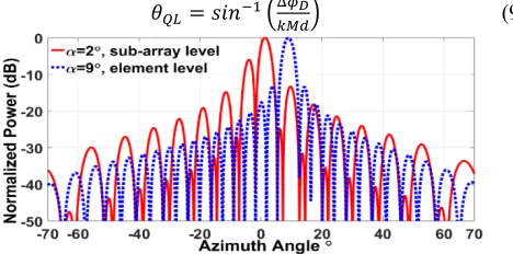
When the beam is steered at 𝛼𝛼 the quantization errors result in the formation of quantization lobes. The quantization lobes occur at the position of grating lobes. The quantization lobe amplitudes increase with increase in the beam steering angle. The effect of quantization lobes on the overall super array pattern is given in Fig. 11 as 𝛼𝛼 increases from 2° to 9°. Even for a small steering angle of 𝛼𝛼 =2° quantization lobes appear due to larger phase quantization steps as phase shifting is at the sub-array level as shown in Fig. 9(a). For element level phase shifters in Fig. 9(b) the levels of quantization lobes are marginal even for 𝛼𝛼 =9°. The sub-array elements have phase progression equal to the quantized phased phase shift Δ𝜙𝜙𝐷𝐷 spaced at 𝑀𝑀×𝑑𝑑. Since 𝑀𝑀×𝑑𝑑 is likely to be several wavelengths long, the sub-arrays will generate a number of quantization lobes at 𝜃𝜃𝑄𝑄𝑄𝑄 given by [82]:
𝜃𝜃𝑄𝑄𝑄𝑄=𝑠𝑠𝑚𝑚𝑚𝑚−1�Δ𝜙𝜙𝐷𝐷
[image:9.612.338.537.190.294.2]𝑘𝑘𝑀𝑀𝑑𝑑� (9)
Fig. 11 28 GHz configuration 𝐶𝐶𝑀𝑀16 azimuth pattern with beam steering.
V. SIMULATION RESULTS
A. Channel Condition Number
With a view to improve the channel condition number for 𝐶𝐶𝑀𝑀4 in Fig. 7, 𝑑𝑑 is increased from 2𝜆𝜆 to 4𝜆𝜆 for the 5×5 MIMO 28 GHz channel. The channel condition numbers in Fig. 12 indicate an improvement of 4 dB from 18.9 dB to 14.9 dB for 50% median values, indicating improved channel performance with increase in lateral separation. However, the later configuration would be severely restricted in terms of adequate beam steering as indicated in Fig. 8.
[image:9.612.65.272.324.415.2]Fig. 12 Channel condition number for 2×2 MIMO configuration 𝐶𝐶𝑀𝑀4. In view of the limitations in the mentioned configuration, an alternative is to increase the number of sub-array elements. This will offer reduction in the HPBW in azimuth leading to increase in directivity. It also increases the lateral separation thereby increasing the possibility of improved channel condition number even for higher configurations such as for 3×3 and 4×4 MIMO. Consider 𝐶𝐶𝑀𝑀8with two sub-arrays each with d=4λ to ensure condition in (1) which now corresponds to a single ULA of 16 elements. The channel condition number is plotted in Fig. 13 indicating lower 50% median values of 6.5 dB, 10.6 dB and 14.2 dB for 2×2, 3×3 and 4×4 MIMO as compared to the 4-element antenna sub-array configuration 𝐶𝐶𝑀𝑀4 in Fig. 7.
Fig. 13 28 GHz MIMO channel condition number CDF plot for 𝐶𝐶𝑀𝑀8.
[image:9.612.323.543.458.571.2] [image:9.612.48.282.612.728.2]𝐶𝐶𝑀𝑀16 and 𝐶𝐶𝑀𝑀32 can support up to 7×7 with maximum condition numbers ∼ 20 dB. As M increases from 4 to 8, the decrease in the median channel condition number is higher than for further subsequent increases in M. Although there is a trade-off between M and the array size, increasing M will not only increase the number of MIMO channels for SM but have other known benefits such as higher directivity and narrower beamwidth.
Fig. 14 28 GHz MIMO channels.
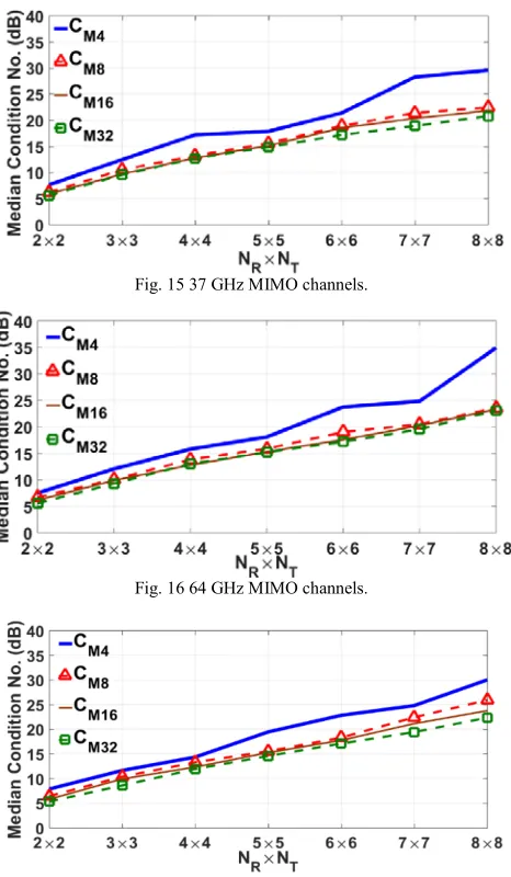
[image:10.612.54.287.333.733.2]Similar variations are observed for 37 GHz, 64 GHz and 71 GHz as in Fig. 15, Fig. 16 and Fig. 17, respectively, which is conformity to the observation that mmWave MIMO channels behave almost identical for LOS channel conditions [45].
Fig. 15 37 GHz MIMO channels.
Fig. 16 64 GHz MIMO channels.
Fig. 17 71 GHz MIMO channels.
B.MIMO Spectral Efficiencies
The spectral efficiency of a MIMO-OFDM system, assuming equal power allocation to each Tx antenna sub-array, can be expressed as follows:
𝑅𝑅=BW1 ∫ffminmaxlog2det (𝐈𝐈+𝑁𝑁ρ𝑇𝑇𝐇𝐇f𝐇𝐇f𝐇𝐇)df (10) where 𝑅𝑅 denotes the spectral efficiency achievable using eigen beamforming, BW represents the RF bandwidth, 𝑓𝑓𝑚𝑚𝑚𝑚𝑚𝑚 and 𝑓𝑓𝑚𝑚𝑚𝑚𝑀𝑀 stand for the minimum and maximum sub-carrier frequency, respectively, 𝜌𝜌 is the received SNR, 𝑁𝑁𝑇𝑇 denotes the number of transmit antenna sub-arrays, and 𝐇𝐇𝒇𝒇 represents the MIMO channel matrix in the spatial domain (normalized by the corresponding path loss) for the sub-carrier frequency 𝑓𝑓. Fig. 18 shows the spectral efficiency as a function of received SNR for a MIMO-OFDM channel with three transmit antenna arrays and two receive antenna sub-arrays for a variety of sub-array spacing at 28 GHz. It is evident from Fig. 18 that the spectral efficiency increases as the sub-array spacing grows from 1/2λ to 4λ for a fixed SNR. It is noteworthy that an increase of the sub-array spacing from 2λ to 4λ does not increase the spectral efficiency as substantially as from 1/2λ to λ and from λ to 2λ, which indicates that further increasing the sub-array spacing may not have a significant impact on spectral efficiency.
Fig. 18 Spectral efficiency for 28 GHz MIMO-OFDM channel with three transmit antenna sub-arrays and two receive antenna sub-arrays.
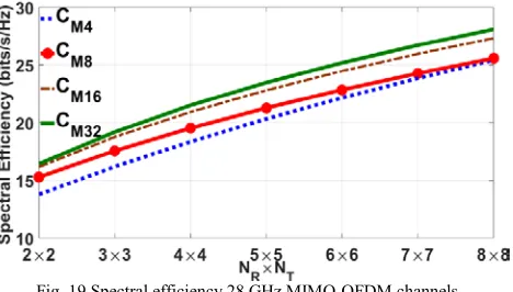
As the number of sub-array elements M increases the HPBW reduces leading to a more pencil beam which increases SM in LOS-MIMO. However the increase in dividend cannot be expected for ever increasing values of M. At 28 GHz frequency this is evident from Fig. 19 in which the spectral efficiency increases, as the sub-array spacing d
increases. The increase in d is due to increase in lateral separation of the sub-arrays as M increases. However the increase in spectral efficiency is most significant only when
[image:10.612.327.554.344.469.2]Fig. 19 Spectral efficiency 28 GHz MIMO-OFDM channels.
Figs. 20-22 illustrate achievable spectral efficiency of MIMO channels with ULA sub-array spacing of 2𝜆𝜆 (𝐶𝐶𝑀𝑀4), 4𝜆𝜆 (𝐶𝐶𝑀𝑀8), 8𝜆𝜆(𝐶𝐶𝑀𝑀16), and 16𝜆𝜆 (𝐶𝐶𝑀𝑀32) at the Tx and Rx at 37, 64, and 71 GHz, respectively indicating similar behaviour in terms of increase in M and the corresponding spectral efficiencies that are achieved. Furthermore, for an identical sub-array spacing, the average SNRs and spectral efficiencies are the highest at 28 GHz, and are slightly lower at 37 GHz, while 64 GHz channel yield the lowest average SNR and spectral efficiency due to severe oxygen absorption and/or other types of attenuation.
Channel condition numbers and MIMO capacities indicate good correlation in terms of channel performance. Channel condition numbers indicate a value of ~20 dB for 7×7 MIMO at all the frequencies except at 64 GHz which is 24 dB, and also has the lowest spectral efficiency. As increase in spectral efficiency is most at 8𝜆𝜆 (𝐶𝐶𝑀𝑀16) it may not be necessary to employ arrays with a higher number of sub-array elements. From Table 1 the 𝐶𝐶𝑀𝑀16array size is in the range of 6.5-16.6 cm depending on the frequency for 2×2 MIMO and this range increases to 26.83-68 cm for a 7×7 MIMO channel.
[image:11.612.327.564.51.183.2]Fig. 20 Spectral efficiency 37 GHz MIMO OFDM channels.
Fig. 21 Spectral efficiency 64 GHz MIMO-OFDM channels.
Fig. 22 Spectral efficiency 71 GHz MIMO-OFDM channels.
VI. CONCLUSIONS
An architecture for ULAs based on beamforming with SM for mmWave in 5G mobile services is proposed in this paper. The approach utilizes a single array that can employ single or multiple beams for beamforming at low SNR and cell edge scenarios. The array comprises of sub-arrays that configure as radiating elements for SM in high SNR LOS conditions for MIMO channels to increase the peak data rates, thereby giving flexibility of employing a single ULA architecture that can be employed in both low and high SNR MIMO conditions. The ULA element has been designed with CST MICROWAVE STUDIO® and array patterns developed using MATLAB R2016a® generating HPBW input parameters for the NYUSIM v1.5 simulator. Simulation results obtained from the NYUSIM v1.5 simulator indicate spectral efficiencies of 18.5-28.1 bits/s/Hz with a sub-array spacing of 16 wavelengths for outdoor mmWave urban LOS transmission at the recently allocated 5G carrier frequencies by the FCC in July 2016. Formation of two or more spatial lobes for the AODs and AOAs even for LOS scenarios in mmWave propagation is a characteristic that can be leveraged by beamforming and employed for SU-MIMO where the transmitting and receiving array elements can be co-located. The proposed architecture not only ensures adequate coherency between the array elements required for beamforming, but also results in adequate spatial separation during SM without violating the conditions for grating and quantization lobe formation that restricts the beam steering angle. The analysis will be extended to uniform rectangular arrays (URAs), the results of which may be reported in a future publication.
REFERENCES
[1] 3GPP, “Study on channel model for frequencies from 0.5 to 100 GHz,” 3GPP TR 38.901 Release 14 V14.1.0, Jun. 2017. [Online]. Available: https://portal.3gpp.org/desktopmodules/Specifications/SpecificationDet ails.aspx?specificationId=3173
[2] T. S. Rappaport et al., “Millimeter wave mobile communications for 5G cellular: It will work,” IEEE Access, vol. 1, pp. 335-349, May 2013. [3] Cisco Visual Networking Index, "Global mobile data traffic forecast
update," 2015–2020 White Paper (Feb. 1, 2016). [Online]. Available: http://www.cisco.com/c/en/us/solutions/collateral/service-
rovider/visualnetworking-index-vni/mobile-white-paper-c11-520862.html
[image:11.612.54.289.449.732.2][5] Federal Communications Commission FCC 16-89, Jul. 2016. [Online]. Available:
https://apps.fcc.gov/edocs_public/attachmatch/FCC-16-89A1.pdf
[6] F. Boccardi et al., “Five disruptive technology directions for 5G,” IEEE Commun. Mag., vol. 52, no. 2, pp. 74-80. Feb. 2014.
[7] W. Roh et al., “Millimeter-wave beamforming as an enabling technology for 5G cellular communications: Theoretical feasibility and prototype results,”IEEE Commun. Mag., vol. 52, no. 2, pp. 106-113, Feb. 2014.
[8] A. L Swindlehurst, E. Ayanoglu, P. Heydari, and F. Capolino, “Millimeter-wave massive MIMO: The next wireless revolution?,”
IEEE Commun. Mag., vol. 52, no. 9, pp. 56-62. Sept. 2014.
[9] M. Fakharzadeh, M.R. Nezhad-Ahmadi, B. Biglarbegian, J. AhmadiShokouh, and S. Safavi-Naeini, “CMOS phased array transceiver technology for 60 GHz wireless applications,” IEEE Trans. Antennas Propag., vol. 58, no. 4, pp. 1093–1104, Apr. 2010.
[10] A. Poon and M. Taghivand, “Supporting and enabling circuits for antenna arrays in wireless communications,” Proc. IEEE, vol. 100, no. 7, pp. 2207–2218, Jul. 2012.
[11] X. Zhang, A. F. Molisch, and S. Kung, “Variable-phase-shift-based RF baseband codesign for MIMO antenna selection,” IEEE Trans. Signal Process., vol. 53, no. 11, pp. 4091–4103, Nov. 2005.
[12] V. Venkateswaran and A.-J. van der Veen, “Analog beamforming in MIMO communications with phase shift networks and online channel estimation,” IEEE Trans. Signal Process., vol. 58, no. 8, pp. 4131–4143, Aug. 2010.
[13] S. Kutty and D. Sen, “Beamforming for millimeter wave communications: An inclusive survey,” IEEE Commun. Mag., vol. 18, no. 2, pp. 949-973, Dec. 2015.
[14] F. Sohrabi and W.Yu, “Hybrid digital and analog beamforming design for large-scale antenna arrays,” IEEE J. Sel. Topics Signal Process.,
vol. 10, no. 3, pp. 501-513, Apr. 2016.
[15] A. Hajimiri, H. Hashemi, A. Natarajan, X. Guan, and A. Komijani, “Integrated phased array systems in silicon,” Proc. IEEE, vol. 93, no. 9, pp. 1637–1655, Sep. 2005.
[16] F. Pivit and V. Venkateswaran, “Joint RF-feeder network and digital beamformer design for cellular base-station antennas,” in Proc. IEEE Antennas Propag. Soc. Int. Symp. (APSURSI), Jul. 2013, pp. 1274– 1275.
[17] G. Wang, H. Ding, W. Woods, and E. Mina, “Wideband on-chip RF MEMS switches in a BiCMOS technology for 60 GHz applications,” in Proc. Int. Conf. Microw. Millimeter Wave Technol. (ICMMT), vol. 3, Apr. 2008, pp. 1389–1392.
[18] S. Sun et al., “Investigation of prediction accuracy and parameter stability of large scale propagation path loss models for 5G wireless communications,” IEEE Trans. Veh. Technol., vol. 65, no. 5, pp. 2843-2860, May 2016.
[19] S. Sun, T. S. Rappaport, R. W. Heath, A. Nix, and S. Rangan, “MIMO for millimeter-wave wireless communications: Beamforming, spatial multiplexing, or both?”, IEEE Commun. Mag., vol. 52, no.12, pp. 110–121, Dec. 2014.
[20] W. Cai, P. Wang, Y. Li, Y. Zhang, and B. Vucetic, “Deployment optimization of uniform linear antenna arrays for a two-path millimetre wave communication system,” IEEE Commun. Letters, vol. 19, no. 4 pp. 669-672, Apr. 2015.
[21] P. Wang, Y. Li, X. Yuan, L. Song, and B. Vucetic, “Tens of gigabits wireless communication over E-band LOS MIMO channels with uniform linear arrays,” IEEE Trans. Wireless Commun., no. 13, vol.7, pp. 3791-3805, Jul. 2014.
[22] D. Gesbert, H. Bolcskei, D. A. Gore, and A. J. Paulraj, “Outdoor MIMO wireless channels: Models and performance predication,”
IEEE Trans. Commun., vol. 50, no. 12, pp. 1926–1934, Dec. 2002. [23] F. Bohagen, P. Orten, and G. E. Oien, “Design of optimal high-rank
lineof-sight MIMO channels,” IEEE Trans. Wireless Commun., vol. 6, no. 4, pp. 1420–1424, Apr. 2007.
[24] I. Sarris and A. R. Nix, “Design and performance assessment of highcapacity MIMO architectures in the presence of a line-of-sight component,” IEEE Trans. Veh. Technol., vol. 56, no. 4, pp. 2194– 2202, Jul. 2007.
[25] F. Bohagen, P. Orten, and G. E. Oien, “On spherical vs. plane wave modeling of line-of-sight MIMO channels,” IEEE Trans. Commun., vol. 57, no. 3, pp. 841–849, Mar. 2009.
[26] E.Torkildson, B. Ananthasubramanium, U. Madhow, and M. Rodwell “Millimeter-wave MIMO: Wireless links at optical speeds”, in Proc. 44th Annual Allerton Conf. Comm. Cont. Comp.,
Illinois, Sept 2006. Available at:
http://www.ece.ucsb.edu/Faculty/rodwell/publications_and_presentat ions/publications/Torkildoson_Allerton_2006.pdf.
[27] E. Torkildson, C. Sheldon, U. Madhow, and M. Rodwell “Millimeter-wave spatial multiplexing in an indoor environment”, IEEE GLOBECOM Workshops, Hawaii USA, Dec 2009, pp. 1-6. [28] O. El Ayach, S. Abu-Surra, S. Rajagopal, Z. Pi, and R.W. Heath Jr,
"Spatially sparse precoding in millimeter wave MIMO systems,"
IEEE Trans. Wire. Commun., vol. 13, no. 3, pp. 1499–1513, Jan. 2014. [29] F. Khalid and J. Speidel, "Robust hybrid precoding for multiuser MIMO wireless communication systems," IEEE Trans. Wireless Commun., vol. 13, no. 6, pp. 3353-3363, Jun. 2014.
[30] X. Yu, J. Shen, J. Zhang, and Khaled B. Letaief, "Alternating minimization algorithms for hybrid precoding in millimeter wave MIMO systems," IEEE J. Sel. Topics Signal Process., vol. 10, no. 3, pp. 485-500, Apr. 2016.
[31] A. Li and C. Masouros, "Hybrid analog-digital millimeter-wave MU-MIMO Transmission with Virtual Path Selection," IEEE Commun. Lett., vol. 21, no. 2, pp. 438-441, Feb. 2017.
[32] C. Lee and W. Chung, "Hybrid RF-baseband precoding for cooperative multiuser massive MIMO systems with limited RF chains," IEEE Trans. Commun., vol. 65, no. 4, pp. 1575-1589, Apr. 2017.
[33] S. Park, J. Park, A. Yazdan, and R. W. Heath, "Exploiting spatial channel covariance for hybrid precoding in massive MIMO systems,"
IEEE Trans. Signal Process., vol. 65, no. 14, pp. 3818-3822 Jul. 2017. [34] W. Ni and X. Dong, “Hybrid block diagonalization for massive multiuser MIMO systems,” IEEE Trans. Commun., vol. 64, no. 1, pp. 201–211, Jan. 2016.
[35] L. Liang, W. Xu, and X. Dong, “Low-complexity hybrid precoding in massive multiuser MIMO systems,” IEEE Wireless Commun. Lett., vol. 3, no. 6, pp. 653–656, Dec. 2014.
[36] F. Sohrabi and W. Yu, “Hybrid digital and analog beamforming design for large-scale antenna arrays,” IEEE J. Sel. Topics Signal Process., vol. 10, no. 3, pp. 501–513, Apr. 2016.
[37] S. Han, C. Rowell, Z. Xu, S. Wang, and Z. Pan, “Large scale antenna system with hybrid digital and analog beamforming structure,” in
Proc. IEEE Int. Conf. Commun., Jun. 2014, pp. 842–847.
[38] A. Alkhateeb, G. Leus, and R. Heath, “Limited feedback hybrid precoding for multi-user millimeter wave systems,” IEEE Trans. Wireless Commun., vol. 14, no. 11, pp. 6481–6494, Nov. 2015. [39] R. Stirling-Gallacher and M. Rahman, “Multi-user MIMO strategies
for a millimeter wave communication system using hybrid beam-forming,” in Proc. IEEE Int. Conf. Commun., Jun. 2015, pp. 2437– 2443.
[40] T. Bogale and L. Le, “Beamforming for multiuser massive MIMO systems: Digital versus hybrid analog-digital,” in Proc. IEEE Global Commun. Conf., Dec. 2014, pp. 4066–4071.
[41] A. Adhikary, J. Nam, J. Ahn, and G. Caire, “Joint spatial division and multiplexing: The large-scale array regime,” IEEE Trans. Inf. Theory, vol. 59, no. 10, pp. 6441–6463, Oct. 2013.
[42] X. Gao, L. Dai, S. Han, C.-L. I, and R. W. Heath, "Energy-efficient hybrid analog and digital precoding for mmWave MIMO systems with large antenna arrays," IEEE J. Sel. Areas Commun., vol. 34, no. 4, pp. 998-1009, Apr. 2016.
[43] S. Park, A. Alkhateeb, and R. W. Heath, "Dynamic Subarrays for Hybrid Precoding in Wideband mmWave MIMO Systems," IEEE Trans. Wireless Commun., vol. 16, no. 5, pp. 2907-2920, May 2017. [44] Jian A Zhang, Xiaojing Huang, Val Dyadyuk and Y. Jay Guo,
“Massive hybrid antenna array for millimetre-wave cellular communications,” IEEE Wireless Commun. Mag., pp. 79-87, Feb. 2015.
[45] "Spatial Channel Model for Multiple Input Multiple Output (MIMO) Simulations," document 3GPP TR 25.996 V12.0.0, Sep. 2014. [Online]. Available:
https://portal.3gpp.org/desktopmodules/Specifications/Specification Details.aspx?specificationId=1382
[46] M.K. Samimi and T.S. Rappaport, “3-D Millimeter-Wave Statistical Channel Model for 5G Wireless System Design,” IEEE Trans. Microw. Theory Techn.,vol. 64, no. 7, pp. 2207-2225, Jul. 2016. [47] T. S. Rappaport, G. R. MacCartney, Jr., M. K. Samimi, and S. Sun,
[48] NYU WIRELESS NYUSIM v1.5 Open Source Downloadable 5G Channel Simulator Software, Feb. 2017. [Online]. Available: http://wireless.engineering.nyu.edu/nyusim
[49] S. Sun, G. R. MacCartney, and T. S. Rappaport, “A novel millimetre-wave channel simulator and applications for 5G wirelesss communications,” in Proc. IEEE Int. Conf. Commun., (ICC), May 2017, pp. 1-7.
[50] T.S. Rappaport,S. Sun, and M. Shafi,"5G Channel model with improved accuracy and efficiency in mmWave bands," IEEE 5G Tech Focus, Mar 2017. [Online]. Available: http://5g.ieee.org/tech-focus#channelmodel.
[51] A. Adhikary et al., “Joint spatial division and multiplexing for mmWave channels,” IEEE J. Sel. Areas Commun., vol. 32, no. 6, pp. 1239–1255, Jun. 2014.
[52] D. Tse and P. Vishwanath, Fundamentals of Wireless Communication, Cambridge University Press 2005.
[53] A Poon, R. Broderson, and D. Tse, “Degrees of freedom in multiple-antenna channels: a signal space approach,” IEEE Trans. Inf. Theory,
vol. 51, no. 2, pp. 523-536, Feb. 2005.
[54] R.W. Heath and D. J. Love, “Multimode antenna selection for spatial multiplexing systems with linear Rxs,” IEEE Trans. Signal Process. , vol. 53, no. 8, pp. 3042–3056, Aug. 2005.
[55] X. Lu et al., “An improved semi-orthogonal user selection algorithm based on condition number for multiuser MIMO systems,” China Commun. vol. 11, no. 13, pp. 23–30, 2014.
[56] T. S. Rappaport, R. W. Heath, Jr., R. C. Daniels, and J. N. Murdock,
Millimeter Wave Wireless Communications. Englewood Cliffs, NJ, USA Prentice-Hall 2015.
[57] Q. H. Abbasi, H. E. Sallabi, E. Serpedin, K. Qaraqe, and A. Alomainy, “Condition number variability of ultra-wideband MIMO on body channels,” in Proc. IEEE Int. Work. Ant. Tech.,(iwat), Mar. 2016, pp.167-169.
[58] N. Bourbaki, Elements of Mathematics, Algebra I. Hermann 1974. [59] V. Erceg, P. Soma, D. S. Baum, and A. J. Paulraj, “Capacity obtained
from multiple-input multiple-output channel measurements in fixed wireless environments at 2.5 GHz," in Proc. IEEE Int. Conf. Commun. (ICC), vol. 1, May 2002, pp. 396-400.
[60] M. D. Batariere et al., “Wideband MIMO mobile impulse response measurements at 3.7 GHz," in Proc. IEEE Veh. Technol. Conf. (VTC), May 2002, pp. 26-30.
[61] M. Matthaiou, D.I. Laurenson, and C.-X.Wang, “On analytical derivations of the condition number distributions of dual non-central wishart matrices,” IEEE Trans. Wireless Commun., vol. 8, pp. 1212-1217, Mar. 2009.
[62] M. Matthaiou, M. R. McKay, P. J. Smith, and J. A. Nossek, “On the condition number distribution of complex wishart matrices,” IEEE Trans. Commun., vol. 58, pp. 1705-1717, Jun. 2010.
[63] M. Matthaiou, D. I. Laurenson, and C. X. Wang, “Reduced complexity detection for Ricean MIMO channels based on condition number thresholding,” in Proc. Int. Wireless Commun. Mob. Comp. Conf., pp. 988–993, Aug. 2008.
[64] R. Heath, Jr. and D. Love, “Multimode antenna selection for spatial multiplexing systems with linear receivers,” IEEE Trans. Signal Process., vol. 53, no. 8, pp. 3042-3056, Aug 2005.
[65] R. W. Heath and A. J. Paulraj, “Switching between multiplexing and diversity based on constellation distance,” IEEE Trans. Commun., vol. 53, no.6, pp. 962-968, Jun. 2005.
[66] H. Artes, D. Seethaler, and F. Hlawatsch, “Efficient detection algorithms for MIMO channels: a geometrical approach to approximate ML detection,” IEEE Trans. Signal Process., vol. 51, no. 11, pp. 2808-2820, Nov. 2003.
[67] D. Wubben, R. Bohnke, V. Kuhn, and K. D. Kammeyer, “MMSE-based lattice-reduction for near-ML detection of MIMO systems, ” in
Proc. ITG Work. Smart Antennas (WSA), Mar. 2004, pp. 106-113. [68] J. Maurer, G. Matz, and D. Seethaler, “Low-complexity and
fulldiversity MIMO detection based on condition number thresholding,” in Proc. IEEE Int. Conf. Acoustics Speech Signal Process. (ICASSP), vol. 3, Apr. 2007, pp. 61-64
[69] L. Zhou and M. Shimizu, “A novel condition number-based antenna shuffling scheme for DSTTD OFDM system,” in Proc. IEEE Veh. Tech. Conf., Apr. 2009, pp. 1-5.
[70] D. Wubben, V. Kuhn, and K. D. Kammeyer, "On the robustness of lattice-reduction aided detectors in correlated MIMO systems," in
Proc. IEEE Veh. Tech. Conf., Apr. 2004, pp. 3639-3643.
[71] Y. Zeng and Y.-C. Liang, “Eigenvalue based spectrum sensing algorithms for cognitive radio," IEEE Trans. Commun., vol. 57, no. 6, pp. 1784-1793, Jun. 2009.
[72] F. Penna, R. Garello, and M. Spirito, “Cooperative spectrum sensing based on the limiting eigenvalue ratio distribution in Wishart matrices," IEEE Commun. Lett., vol. 13, no. 7, pp. 507-509, Jul. 2009. [73] L. S Cardoso, M. Debbah, P. Bianchi, and J. Najim, “Cooperative
spectrum sensing using random matrix theory," in Proc. IEEE Int. Symp. Wireless Perv. Comput. (ISWPC), May 2008, pp. 334-338. [74] T. H. Chan and M. Hamdi, “A link adaptation algorithm in
MIMO-based WIMAX systems,” Journal Commun., vol. 2, pp. 16-24, Aug. 2007.
[75] J.Zik and B.Hoefler, “Maximizing LTE MIMO Throughput using Drive Test Measurements,” PCTEL RF Solutions, Oct. 2010. [Online]. Available:www.rfsolutions.pctel.com/artifacts/
MIMOThroughputDriveTestWebinar.pdf
[76] 3GPP, “Study on 3D channel model for LTE,” Technical Report 2015,
3GPP TR 36.873. [Online]. Available:
https://portal.3gpp.org/desktopmodules/Specifications/Specification Details.aspx?specificationId=2574
[77] L. Chang, W. Lai, J. Cheng, and C. Hsue, “A symmetrical reconfigurable multipolarization circular patch antenna”, IEEE Antennas Wireless Propag. Lett., vol. 13, pp. 78-90, Jan. 2014. [78] B. Babakhani, S. K. Sharma, and N. R. Labadie, “A frequency agile
microstrip patch phased array antenna with polarization reconfiguration”, IEEE Trans. Antennas Propag., vol. 64, no. 10, pp. 4316-4327, Oct. 2016.
[79] D. Guha and C. Kumar, “Microstrip patch versus dielectric resonator antenna bearing all commonly used feeds: An experimental study to choose the right element”, IEEE Antennas Propag. Mag., pp. 45-55, Feb. 2 0 1 6.
[80] R. Kellerman, “L-band dual fed EM coupled circularly polarized circular stacked patch phased array design using Antenna Magus and CST MICROWAVE STUDIO”, Antenna Magus Application Note, Nov. 2016. [Online]. Available:
http://www.antennamagus.com/applicationnotes.php?note=5 [81] A. D Brown, Electronically Scanned Arrays, MATLAB® Modeling
and Simulation: CRC Press Taylor Francis Group, 2012. [82] R. C. Hansen, Phased Array Antennas: John Wiley & Sons, 2009.