2017 International Conference on Mathematics, Modelling and Simulation Technologies and Applications (MMSTA 2017) ISBN: 978-1-60595-530-8
Modeling and Simulation of Energy Recovery and Stability for Parallel
Hybrid Electric Vehicle Based on CarSim-Simulink
Zhen-zhou YOU
1, Ji-chan XU
2and Li-min NIU
3,*1Department of Mechanical Engineering, Wenzhou Vocational and
Technical College, Wenzhou 325035, China
2Science Island Branch of Graduate School, University of Science and
Technology of China, Hefei 230031, China
3School of Mechanical Engineering, Anhui University of Technology, Ma’anshan 243002, China
*Corresponding author
Keywords: Modeling, Parallel HEV, Energy recovery, Stability, CarSim-Simulink.
Abstract. The energy recovery system of the parallel hybrid electric vehicle (HEV) tend to affect the vehicle stability, this paper analyzed the structure of the parallel HEV energy recovery system with the semi-active suspension system (SAS) and the anti-lock braking system (ABS), then built a parallel HEV energy recovery system model in the CarSim-Simulink platform, including the power, the brake, the ABS, the SAS, the controller and the whole vehicle dynamics models. Two models of integration and independent control strategy are set up and simulated respectively, the results show that integration control strategy can better keep vehicle stability, and reasonably allocate the energy recovery ratio to improve fuel economy, and indicate that the model is available for the research of control strategy between energy recovery and vehicle stability.
Introduction
The energy recovery system in a parallel hybrid electric vehicle (HEV) is an important component to recycle and store the excess kinetic energy and potential energy during the braking, downhill, idling etc conditions, aim to make full use of the electrical energy, and effectively improve the HEV's fuel economy[1, 2]. However, the energy recovery system generally produce additional forces to the vehicle during recycling kinetic energy or potential energy, which will change the original braking allocation of the vehicle, thus affected the vehicle power composition and stability [3-5]. Therefore, it is necessary to build a proper model of the parallel HEV for studying the control strategy of the vehicle stability during effectively energy recovery process. CarSim, as a vehicle multi-body dynamics software, is widely used for the prediction and simulation of the vehicle stability and fuel economy performance characteristics, and has a friendly interface with Simulink software to jointly build an external module of vehicle system, which makes the modeling more flexible[6, 7].
In this paper, the parallel HEV with the semi-active suspension system (SAS) and ABS system, which play important roles in controlling the stability of vehicle during the braking and downhill cases[8], is studied. The structure and working principle of the energy recovery system are analyzed. Then the parallel HEV model is built on the vehicle multi-body dynamics CarSim software platform with the Simulink software, including the vehicle dynamic system model, the brake system model, the ABS system model, the SAS system model and controller model. Finally, the integration controller and independent controller models are simulated and analyzed. The results show that the integration control can better coordinate the relationship between energy recovery and vehicle stability, and verify that the model is useful for the control strategy research.
Structural Analysis of Energy Recovery System
motor, the engine and motor are connected in parallel, which can provide the power separately or together. The integrated started generator (ISG), as electric motor, can be used as the output power of the motor and also can be converted into electric energy and stored in the battery. Engine and motor are controlled by controlling two clutchs, respectively. The torque coupler will control torque transmission, which can be used to drive the vehicle through transmission, or transferred to ISG motor for energy recovery in different operating conditions[9, 10]. The SAS system consists of four damping adjustable suspensions, including throttle valve dampers which are controlled by the stepper motor, then the vehicle's ride comfort can be improved by controlling the stepper motor [7]. The brake system consists of the brake pedal, stroke simulator and electronic control brake, and equipped with ABS system to control four-wheel braking, respectively. The brake pedal stroke simulator receives signals from the brake pedal, and converted electrical signals to electronic control brake, then jointly controlled the four wheel braking force with ABS system according to the wheel speed sensor signals, brake hydraulic signal, etc, thus make the vehicle more stable and safe when braking [11].
Figure 1. Structure of parallel HEV energy recovery system.
Model of Energy Recovery System
According to the analysis of the parallel HEV energy recovery system structure in previous section, it can be divided into power system, brake system, ABS system, SAS system, vehicle dynamics and the system controller, as shown in Figure 2. The brake system and ABS system work together for the vehicle's braking process. The corresponding ECU modules are set up in each subsystem model, and can interact with each other. The system controller model receives signals from subsystems and vehicle dynamics models, then outputs corresponding regulatory factor to each subsystem model through the existed control strategy, to realize the control of vehicle stability and the energy recovery.
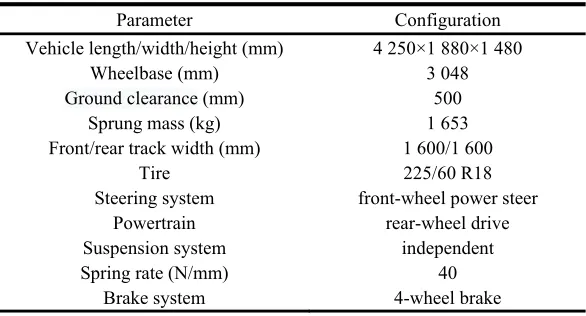
[image:2.612.245.367.585.705.2]The vehicle dynamics model is built by setting the parameters in the CarSim software, and other models are built in Simulink software. The original engine drive system, shock absorber and brake system in vehicle dynamics model are removed, instead of rear wheel drive torque, four-wheel brake wheel chamber pressure and four suspension shock absorber damping force as the input signals, and the speed, acceleration, wheel speed, body roll angle, wheel vertical load, body pitch angle, vertical acceleration of body mass center, and damper compressibility as the output signals, which are used as the interface to connect the models in the Simulink software. The parameters of CarSim vehicle dynamics model are shown in Table 1.
Table 1. Parameters of vehicle dynamics model on CarSim.
Parameter Configuration
Vehicle length/width/height (mm) 4 250×1 880×1 480
Wheelbase (mm) 3 048
Ground clearance (mm) 500
Sprung mass (kg) 1 653
Front/rear track width (mm) 1 600/1 600
Tire 225/60 R18
Steering system front-wheel power steer
Powertrain rear-wheel drive
Suspension system independent
Spring rate (N/mm) 40
Brake system 4-wheel brake
Power System
[image:3.612.204.407.470.575.2]The schematic diagram of the parallel HEV power system model in the Simulink software is shown in Figure 3. The model set up the fuel engine module and ISG motor module, the power torque (T) is transmitted to the vehicle model as the rear wheel drive force through the clutch A/B module, the torque coupler module and the powertrain model. Meanwhile, the torque transfer is reversible, the power torque (T) from the vehicle model or engine module also can be passed to the ISG motor, and stored in the battery module, which are controlled by the corresponding control strategies in a power controller model.
Figure 3. Schematic diagram of power system model.
The schematic diagram of the power controller model of parallel HEV is shown in Figure 4. The model firstly determines the information of vehicle condition and operation condition under the judging rules. The vehicle condition includes braking, idling, uphill, downhill, speed up and constant
speed, by receiving the signals such as braking stroke(Lb), speed(v), acceleration(a), the pitch angle,
logical rules. Finally distributed the power effectively and reasonably, and made full use of the braking force and driving force from the motor, to get an effective way in energy recycling and keeping the stability of vehicle driving.
Figure 4. Schematic diagram of power controller model
Brake and ABS System
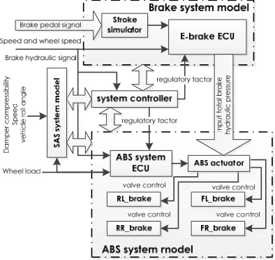
The brake systems usually work together with the ABS system to control the hydraulic braking force of four-wheels. Figure 5 shows the schematic diagram of brakes and ABS system models built in the Simulink software. Stroke simulator is used to convert the brake pedal signal into electrical signal, and transferred to E-brake ECU module. E-brake ECU module also gets the signals of speed, wheel speed and braking hydraulic, and the regulating factor inferred from the system controller model. Finally the ABS actuator obtains the value of the total brake hydraulic derived from the corresponding control strategy.
Figure 5. Schematic diagram of brakes and ABS system models.
[image:4.612.208.405.404.590.2]SAS System
[image:5.612.204.417.192.329.2]The SAS system implements the control of the vehicle driving stability by controlling the shock absorber damping forces. In Figure 6, the schematic diagram of SAS system model in the parallel HEV energy recovery system is shown, SAS system ECU module receives the damper compressibility, speed, vehicle roll angle and the wheel vertical load information from vehicle dynamics CarSim model, and gets the regulatory factor, then outputs four shock absorber damping forces with a fuzzy logic control strategy. Meanwhile, controlled the step pulse signals to regulate the four dampers’ damping force in the parallel HEV vehicle suspension system, so that realize the driving comfort.
Figure 6. Schematic diagram of SAS system model.
Controller Model and System Connection
In the process of driving, the motor provides a part of braking or driving force, so other system controllers must considers the effects from the motor, to better keep the vehicle system working normally. In this paper, we design an integrated coordinated controller model to realize optimal driving state, by judging the states of the power systems, ABS system, brake system and vehicle system in the parallel HEV, and output the corresponding regulatory factors to each subsystem.
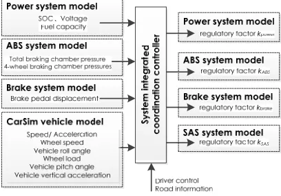
[image:5.612.204.408.563.705.2]Figure 7 shows the schematic diagram of system controller model in the parallel HEV energy recovery system model, the system controller obtains and analyzes the signals, including the signals of battery SOC, voltage and fuel quantity from the power system model, the signals of total braking hydraulic and four-wheel brake hydraulic brake from the ABS system model, the pedal stroke signal from brake system model, the signals of speed, acceleration, wheel speed, body roll angle, wheel vertical load, the pitch angle and the vertical acceleration from the CarSim vehicle model, as well as the driver control signals and road information, finally output different regulatory factors to the power system, ABS system, brake system and SAS system, as reference variables for the control of each subsystem.
Figure 7. Schematic diagram of system controller model.
system are represented by kpower, kABS, kbrake, kSAS, respectively. Each subsystem control unit receives
the corresponding regulatory factor, and gets the proper outputs to the actuators combined with the other parameters.
Among the all the regulatory factors, the regulatory factor kpower plays a key role in the power
system controlling, and is directly used to coordinate the relationship between braking energy
recovery efficiency and vehicle stability, the function relation is expressed as Ktarget = K * kpower,
where K is the ratio of motor braking torque Tmotor and the total braking torque Ttotal, i.e., K = Tmotor /
Ttotal, Ktarget is the target ratio. The value of battery SOC and the rate of pitch angle ▽δ are selected as
input parameters, and the ▽δ is set a comparable threshold A (where A =2 deg/s), the ▽δ is disposed
by quantity as ▽δ/A. The value of kpower is regarded as only output, and achieved the optimal target
ratio Ktarget based on a fuzzy control strategy.
The value of regulatory factor kABS is set as a coefficient that related to the ratio of rear wheel motor
braking force, and is used to reflect the distribution status of two kinds of braking forces on rear
wheel, so as to optimize the control strategies of ABS system. The value of regulatory factor kbrake is
the coefficient that reflect the driver control, vehicle condition and road information, which acts on
the control of total braking force to ensure the driving safety. The value of regulatory factor kSAS is set
as a coefficient that related to the wheel vertical loads and the ratio of motor braking force, to optimize the damping force of the suspension system in the front and rear wheels.
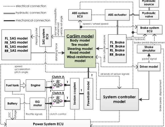
[image:6.612.161.451.490.714.2]In Figure 8, the combined simulation model of parallel HEV energy recovery system on the platform of CarSim-Simulink software is shown, including the CarSim vehicle model, the power system model, the brake system model, the ABS system model, the SAS system model and the system controller model, which are configured the input/output interfaces, respectively. The parallel HEV vehicle Carsim model consists of the body, tires, steering, road surface and wind-resistance models, and is connected with the Simulink models based on the input/output interfaces. The driver model, the power system model, brake system model, ABS system model and SAS system model, as well as the corresponding ECU modules and system controller model by the Stateflow block and Fuzzy Logic Controller block are built in Simulink software. The parallel HEV energy recovery system model is a closed loop simulation system, and need to artificially set different road parameters and the controller type, and then simulating and analyzing the recovery efficiency and the stability of the parallel HEV. The model adopts the modular structure, which is easy to change or optimize the control strategy, and set the operating state of the system controllers in the driver model.
Simulation
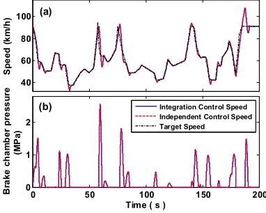
In order to verify the validity and practicability of the model of parallel HEV energy recovery system, the model was set a straight line road condition, and driven by the target speed control method along the side of road in the CarSim, and then simulated. As shown in Figure 9 (a), the maximum vehicle speed is 94.4795 km/h, the minimum speed is 37.4404 km/h, the average speed is 61.0866 km/h, the simulation time is 200s, and the driving distance is 3393.5 m. The model is set as two different control strategies: integrated control strategy and independent control strategy. The independent control model is achieved by closing the system controller and setting the all regulatory factors are equal to 1, and the simulation results are shown in Figure 9 and Figure 10.
As shown in Figure 9 (a) and (b), the actual speed and the hydraulic pressure of the two models are basically same. The pitch angle of the vehicle is one of the important parameters to evaluate the braking and acceleration stability of the vehicle. The battery either provides the electrical energy for driving force during driving, or store the electrical energy transferred from braking energy by the motor, while the engine mainly provides the driving energy. So the pitch angle, the battery SOC and fuel consumption are as the main results of simulation, and shown in Figure 10, respectively.
40 60 80 100 Sp e ed ( k m /h)
0 50 100 150 200
0 1 2
Time ( s )
B rak e ch am be r p re ss u re (M P a)
Integration Control Speed Independent Control Speed Target Speed (a) (b) -0.5 0 0.5 1 Pi tc h a n g le ( d e g ) 0.6 0.7 0.8 SO C ( .a .u )
0 50 100 150 200
0 100 200 300
Time ( s )
[image:7.612.95.286.279.432.2]Fu e l c o n su m p ti o n (m L ) Integration Control Independent Control (a) (b) (c)
Figure 9. Comparison of two control strategy models’ parameter. (a) the actual speed curves and the target
[image:7.612.338.501.279.435.2]speed curves, (b) the total brake hydraulic pressure curves.
Figure 10. Comparison of two control strategy models’
performance. (a) pitch angle curve, (b) SOC curve, (c) fuel consumption curve.
[image:7.612.127.485.607.671.2]Table 2 gives the information about the rates of the parameters for the two models. As can be seen, the integration control model vehicle compares with the independent control model vehicle, the peak pitch angle, the value of SOC values and accumulated fuel consumption declined by 25.8%, 9.55% and 5.07%, respectively. The results indicate that integration control model can makes better use of the recycling energy, and reduces the fuel consumption by using electrical energy in the battery as much as possible, and shows a good operability on the control strategy of the parallel HEV energy recovery system model.
Table 2. The rates of parameters for independent control and integration control models.
Parameter Independent control Integration control Rate of change
Peak pitch (deg) 1.048 0.7776 decline 25.8%
Battery SOC consumption (.a.u) 0.2701 0.2443 decline 9.55%
Total fuel consumption (mL) 298 282.9 decline 5.07%
Conclusion
energy recovery and vehicle stability, and developed the vehicle dynamics model, the power system model, the brake system model, the ABS system model, the SAS system model and the system controller model. Then, a parallel HEV energy recovery system model was constructed by connecting each subsystem model. Finally, the model is set with the integrated and independent control strategies, respectively, and simulated. The results show that the integrated control strategy can make the vehicle more stable, and the energy recycling is more reasonable, and indicate that the model can be easily used for the research of the parallel HEV energy recovery system control strategy.
Acknowledgement
The authors would like to thank the financial support of the Natural Science Foundation of China (Grant No. 51275002), Zhejiang Provincial Key Laboratory of Laser Processing Robot for the open fund (Grant No. lzsy-07), and the key Laboratory for New Technology Application of Road Conveyance of Jiangsu Province (Grant No. BM20082061502).
References
[1] M.F. M. Sabri, K.A. Danapalasingam, M.F. Rahmat, A review on hybrid electric vehicles architecture and energy management strategies, Renewable and Sustainable Energy Reviews, 53 (2016) 1433-1442.
[2] X. Zhang, Z.M. Dong, C. Crawford, Hybrid Energy Storage System for Hybrid and Electric Vehicles: Review and a New Control Strategy, Proceedings of the Asme International Mechanical Engineering Congress and Exposition, 2011, Vol 4, Pts a and B, (2012) 91-101.
[3] M.O. Nicolaica, Vehicle Dynamics Effect on Energy Efficiency in Hybrid Electric Vehicles, 2015 Ieee 17th International Conference on High Performance Computing and Communications, 2015 Ieee 7th International Symposium on Cyberspace Safety and Security, and 2015 Ieee 12th International Conference on Embedded Software and Systems (Icess), (2015) 1669-1672.
[4] J.S. Kim, S.M. Kim, J.H. Jeong, S.C. Jeong, J.W. Lee, Effect of regenerative braking energy on battery current balance in a parallel hybrid gasoline-electric vehicle under FTP-75 driving mode, Int. J. Automotive Technology, 17 (2016) 865-872.
[5] Y.G. Liu, D.Q. Chen, Z.Z. Lei, D.T. Qin, Y. Zhang, R. Wu, Y. Luo, Modeling and control of engine starting for a full hybrid electric vehicle based on system dynamic characteristics, Int. J. Automotive Technology, 18 (2017) 911-922.
[6] F.Z. Ji, X.X. Zhou, W.B. Zhu, Coordinate Control of Electro-hydraulic Hybrid Brake of Electric Vehicles based on Carsim, Mechanical Design and Power Engineering, Pts 1 and 2, 490-491 (2014) 1120-1125.
[7] L. Niu, J. Xu, C. Liu, Research on Simulation Model for Suspension and Steering System Based on CarSim, Mechanical Science and Technology for Aerospace Engineering, (2014) 573-577. [8] L.T. Song, J.J. Chen, Research on Automotive Anti - lock Braking System Based on Simulation Technology, Agro Food Ind Hi Tec, 28 (2017) 917-921.
[9] M. McDonough, Integration of Inductively Coupled Power Transfer and Hybrid Energy Storage System: A Multiport Power Electronics Interface for Battery-Powered Electric Vehicles, Ieee T Power Electr, 30 (2015) 6423-6433.
[10] D.A. Crolla, D.P. Cao, The impact of hybrid and electric powertrains on vehicle dynamics, control systems and energy regeneration, Vehicle Syst Dyn, 50 (2012) 95-109.