2016 International Conference on Mathematical, Computational and Statistical Sciences and Engineering (MCSSE 2016) ISBN: 978-1-60595-396-0
Solving Method of Workspace for 6 DOF Robot Based on Vision
Xiao-man CAO, Xiang-jun ZOU, Yu-da MO and Shao-feng LUO
College of Engineering, South China Agricultural University, Guangzhou 510642, China
Keywords: Workspace, 6 DOF robot, Monte-Carlo method, Simulation.
Abstract. In order to get the solution of the robot workspace, a method that based on the SimMechanics model in Matlab and the Monte-Carlo method was adopted to solve the robot workspace.Matlab/Simulink software was used to realize movement simulation of robot arms and got a compact workspace. Compared to traditional Monte-Carlo method, this method had the advantages of better speed in solving workspace,strong visibility and avoiding complicated mathematical operations, which provided an important basis for robot's obstacle avoidance planning.
Introduction
The workspace of 6 DOF robot represents the range of motion of the robot, which is an important index to measure the ability of robot to work[1]. The calculation methods of the robot workspace mainly include analytic method, graphic method and numerical method. Analytic method presents great complexity and poor visibility[2, 3]. Graphic method has good visibility, but the solution of this method are usually cross section and sectional curves of workspace. It has to be dealt with packet processing as robot has excessive freedom[4, 5]. Numerical method is relatively easy, with use of workspace analysis for arbitrary structural type of robot. Representative results are search method, iterative method and Monte Carlo method, in which Monte Carlo method is the most commonly used method. Monte Carlo method demands to seek forward kinematics and inverse kinematics solution as solving workspace with using numerical method. This would bring large amount of calculation, which leads to lower calculation efficiency, especially calculating workspace of high redundancy robots[6-8].
In order to improve computing efficiency, simulation method for solving the workspace of robot was put forward[9, 10]. Yanjiang Zhao et al. solved workspace using simulation method based on software Matlab/Simulink. The model of single three-degree-of-freedom finger of dexterous hand was modeled and simulated. Then the coordinates of the arm tip in simulation was recorded and exported to Workspace of Matlab. At last, the robotic workspace was drawn and calculated. This method avoided the complex calculation of kinematic solution in the traditional method and movement tracks of robot could be directly observed in the simulation process. Guohua Cui et al. also used the simulation method based on software Matlab/Simulink to solve workspace. But in the solving process, simulation results of only one position could be achieved at a time of simulation. So it needed to compile m-files for multiple simulations to realize continuous simulation. The simulation process was relatively complex. Therefore, this article planned to use both Monte Carlo method and simulation method to solve workspace of 6 DOF robot based on vision, which was able to avoid calculation of kinematic solution and realize continuous simulation with briefness and high-speed.
Principle and Method
Yanjiang Zhao et al. used sinusoidal signal as joint driving signal to simulate. But sinusoidal signal is highly cyclical, that is hard to ensure optimum of the simulation results. Therefore this paper supplied joint driving signal based on Monte Carlo method. Monte Carlo method is a type of numerical method to utilize random sampling to solve math problems, namely, to use random function to generate random values for every joint[8].
(1) This paper would use random value generated by random function as input value of joint driving signal.
So, solution procedure of workspace was:
(1) Establish model of robot arm in Simulink/SimMechanics based on structure diagram and D-H parameters.
(2) Generate random value of every joint by formula (1) and make the random value as the input value of every joint driving signal;
(3) Input different driving signal for every joint and record coordinate data of end of robot arm by sensors;
(4) Start simulation and input data to workspace of Matlab;
(5) Deal with data and generate workspace of 6 DOF robot based on vision.
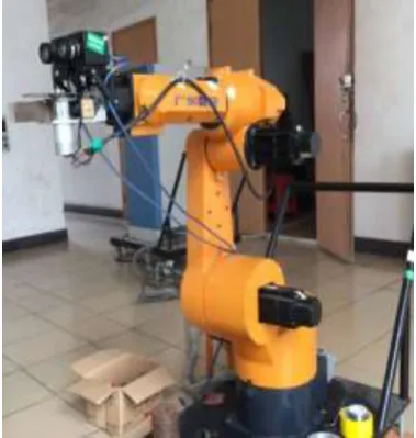
[image:2.595.327.513.378.585.2]HN(SCAU)-6 Robot was a type of open chain structure that was in series connection with connecting rods through rotary joints. It consisted of six- degree-of-freedom robot arm, end-effector and binocular vision system and so on. The structure of the robot was shown in Figure 1.
Figure 1. 6 DOF robot based on vision(HN-6 Robot). Figure 2. Structure diagram of 6 DOF robot based on vision.
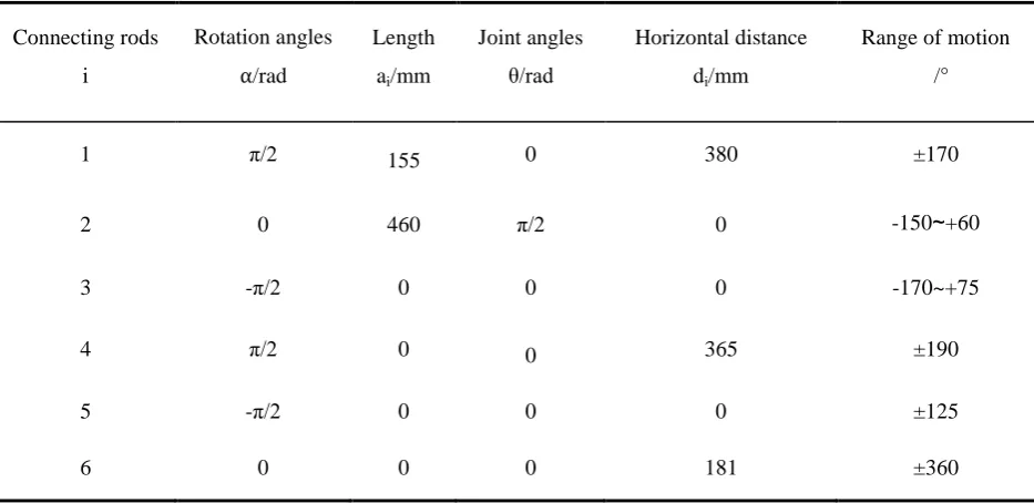
[image:2.595.69.259.380.580.2]Table 1. D-H parameters.
Connecting rods
i
Rotation angles
⍺/rad
Length
ai/mm
Joint angles
θ/rad
Horizontal distance
di/mm
Range of motion
/°
1 π/2 155 0 380 ±170
2 0 460 π/2 0 -150~+60
3 -π/2 0 0 0 -170~+75
4 π/2 0 0 365 ±190
5 -π/2 0 0 0 ±125
6 0 0 0 181 ±360
Modeling and Simulation
Modeling of Robot Arm in Matlab. The structure of 6 DOF robot based on vision was modeled
in Matlab/Simulink/SimMechanics, as shown in Figure 3. The model mainly consisted of a ground module, six rotary joint modules, six driving modules, six rigid-body modules and a sensor module and so on. Rotary joint modules needed to be set the shaft of joints. Driving modules provided driving signal for rotary joints. Rigid-body modules were set based on Table 1. The sensor module recorded the position of where robot arm arrived and exported data to the workspace of Matlab.
Figure 3. Structure modeling of 6 DOF robot based on vision.
Simulation and Analysis of Workspace. After the model was built and every parameters and
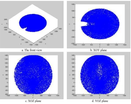
[image:3.595.91.505.440.625.2]Figure 4. The two dimensional workspace of manipulator.
a. The front view b. XOY plane
c. XOZ plane d. YOZ plane
Figure 5. The three dimensional workspace of manipulator.
Summary
[image:4.595.77.520.242.594.2]31571568), Science and Technology Planning Project of Huizhou city (No. 2014B040008006), and Science and Technology Planning Project of Guangdong Province. (No. 2014A010104011). Corresponding Author: Xiangjun Zou.
References
[1] Ruixia Li, Fenxia Li, Jieming Yang, et al. Workspace Analysis of Serial Robot Manipulator Based on D-H Method, Machine Tool and Hydraulics.43(2015):70-73.
[2] Xiandan Zhao, Qingzhong He, Yinghua Liao, et al. Research on Workspace Simulation Program for 3-6 DOFs Serial Manipulator, Modern Manufacturing Technology and Equipment.04(2010):75-76.
[3] Zhizhong Liu, Hongyi Liu, Zhong Luo, et al. Improvement on Monte Carlo Method for Robot Workspace Determination, Translation of CSAM.44(2013):230-235.
[4] Yanjiang Zhao, Yongde Zhang, Jingang Jiang, et al. A Method for Solving Robot Workspace Based on Matlab, Mechanical Science and Technology for Aerospace Engineering. 28(2009):1657-1661.
[5] Yujie Cui, Zuli Zhang, Lei Fan. Working Space Analysis of Picking Manipulator Based on Monte-Carlo Method, 12 (2007):62-63.
[6] Cao Y, Zang H, Wu L, et al. An Engineering Oriented Method for the Three Dimensional Workspace Generation of Robot Manipulator, Journal of Information and Computational Science. 8(2011) : 51-61.
[7] Baofeng Li, Hanxu Sun, Qingxuan Jia, et al. Calculation of Space Robot Workspace by Using Monte Carlo Method, Spacecraft Engneering. 20(2011):79-85.
[8] Haibo Tian, Hongwei Ma, Juan Wei. Workspace and Structural Parameters Analysis for Manipulator of Serial Robot, Translation of CSAM. 44(2013):196-201.
[9] Weibin Xu, Xueliang Ping, Zai'en Ying, et al. Rapid Solving Method for 6R Serial-type Robot Working Space, Journal of Machine Design. 30( 2013):28-31.