2016 International Conference on Electronic Information Technology and Intellectualization (ICEITI 2016) ISBN: 978-1-60595-364-9
A New Testing Method for Dynamic
Positioning Performance of
Navigation Receiver
Huaijian Li, Lijie Yang and Xiaojing Du
ABSTRACT
Dynamic positioning performance of navigation receiver reflects the adaptability of receiver to the dynamic satellite signal. In this paper, a new testing method to test the dynamic positioning precision with dynamic offset directly added to pseudo-range of signal is designed. In this method, the receiver is in a static scene, a same dynamic offset will be added to all the visible satellites’ pseudo-range to change the signal, then the test of pseudo-range measuring and positioning precision can be finished with the changes of the output signal of signal simulator.
INTRODUCTION
The way proposed in this paper finishes the dynamic test of receiver in a static scene, which has the advantages in loading dynamic unaffected by signal incidence direction and satellite movement, and the loading dynamic can be controlled accurately. Therefore, more accurate response of receiver to dynamic signal can be stimulated. To test the dynamic positioning property of receiver, first-order and second-order changing offsets are added to pseudo-range of the signal, and the
________________________
output pseudo-range of receiver declines with the rise of value and order of the offset added, which is in line with the inner loop running property of receiver.
TESTING METHOD
Theory of The Method
In this method, with the addition of off set, the measuring value of pseudo-range is different from its true value, but accurate positioning is still available. The explanation is written blow.
As the pseudo-range equation shows[1]:
s
ur c t t cI cT
(1)
With the offset added in, it changes to equation (2):
s
u
r c t t cI cT
(2)
Measuring value of pseudo-range after revise is write as follow:
s
c t I T
(3)
According to the positioning function:
(1) 2 (1) 2 (1) (1)
(2) 2 (2) 2 (2) 2 (2)
( ) 2 ( ) 2 ( ) 2 ( )
2
u c u c
N N N N
u c t t t ……
(x - x) (y - y) (z - z)
(x - x) (y - y) (z - z)
(x - x) (y - y) (z - z)
(4)
When the offset added in, the same is added to thec( )N of each equation. In theory, the positioning result will be different from that without offset. However, in fact, the receiver can feel the offset of pseudo-range and make response to it. The response acts on the clock error of receiver finally, so atis added to the tuof each equation. And in theory, the t has the same value with , so the positioning
Testing Content
TESTING SCENARIO
GPS signal simulator is used for the test and the simulation scenario is designed as follows: satellite orbit, clock error, ionosphere delay and troposphere delay are all set as error-free model to avoid the influence of them; visible satellite number is more than 6, PDOP value is less than 2.5 and signal power is -133dBm[4].
In the scenario designed above, firstly we use simulator to export the RF signal to the receiver when receiver is in a static scene, then the receiver will export its measuring pseudo-range value and positioning results. All the testing data is saved for comparison with the data of simulator to calculate the measuring and positioning precision. Secondly, add same offset to pseudo-range of each visible satellite to change the RF signal and repeat the testing process in first step, while the offset changes in first-order and second-order. The offset addition process is finished by the control software of signal simulator. Thirdly, compare the pseudo-range measuring and position precision of no offset with different offsets to conclude the principle.
DATA PROCESSING METHOD
With the large amount of data obtained in the testing process, data processing in the way of mathematical statistics is necessary to analyze the changing principle. Pseudo-range measuring precision is calculated in the method designed below [2]:
, ( , 1, ) ( , 1, )
i j xi j x j xi j xj
,i1(5)
2
1 2
n ij j i
n
(6)
max( )i
(7)
,
i j
x is the pseudo-range measuring result of receiver’s channel i at time j;
,
i j
x is the pseudo-range value of simulator’s channel i at time j;
i
TESTING PROCESS
Testing System Composition
The testing system consists of three subsystems. High-dynamic signal simulation system is made up of signal control software and satellite signal simulator. Pseudo-range modification function is its key factor for the testing to add the offset. Data collection system is used for the reception of output data of receiver, which must have the capacity of serial-port communication to connect the receiver. Testing evaluation system analyses and evaluates the data logically, computer program is used.
Testing Scenario Design
(1) Satellite Signal Design
Satellite signal is designed in the condition of Testing Scenario. (2) Error Factor Design
The objective is to test the dynamic measuring performance of tracking loop of receiver, so all the other influential error factors are set as error-free model.
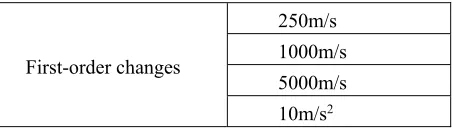
[image:4.612.185.415.403.468.2](3) To finish the simulation analyzing, we design some pseudo-range offset value preliminarily, which is shown in TABLE I:
TABLE I. DESIGN VALUE OF PSEUDO-RANGE OFFSET.
First-order changes
250m/s 1000m/s 5000m/s 10m/s2
Testing Result
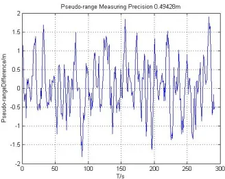
Figure 1. PR precision with offset 250m/s. Figure 2. PR precision with offset 1000m/s.
[image:5.612.93.500.362.460.2]From Figure 1 and Figure 2, we can get that the pseudo-range measuring precision declines with the offset added to signal rises. Results of all channels are in TABLE II.
TABLE II. TESTING RESULTS OF ALL CHANNELS. Signal
Offset changes
Pseudo-range precision of each receiver channel/m Precision of receiver/m
7 8 10 26 29
None 0.335 0.333 0.345 0.333 0.333 0.345 250m/s 0.450 0.435 0.468 0.399 0.478 0.478 1000m/s 0.494 0.447 0.514 0.528 0.503 0.528 5000m/s 0.544 0.452 0.489 0.481 0.470 0.544 10m /s2 0.547 0.501 0.450 0.529 0.496 0.547
CONCLUSION
From TABLE II, we can see that pseudo-range measuring precision declines with the value and order of offset added to the signal rising. That shows the inner loop running property of receiver, so the designed method is proved reasonable enough and with practical application prospect to test the high dynamic positioning performance of navigation receiver. And with all the advantages it has over the traditional testing method, it is a combination of accuracy, efficiency and economy.
REFERENCES
2. Bo Wang, Haisong Jiao, Qing Gu. 2014. Testing and Analysis for Dynamic Positioning Precision of BD Receiver. Journal of Navigation and Positioning, 109-112, in Chinese.
3. Dieudonne M., Vandeplas T., Cresens W. Method for testing a navigation receiver, US20080085704 [P]. 2008.
4. O'Shea M. Monitoring, recording and testing of navigation systems: US, US8423284. 2013. 5. Hu X., Qiao Z., Zhang C. Research on the performance testing method of GNSS receiver.