2016 International Conference on Computer, Mechatronics and Electronic Engineering (CMEE 2016) ISBN: 978-1-60595-406-6
Error Compensation for 3-axis Machine Tools
Fang-yu PAN, Li NIE
*, Yue-wei BAI, Xiao-gang WANG, Kai LIU
and Xiao-yan WU
Shanghai Second Polytechnic University, Industrial Engineering, Room 300, No.14 building, No.2360 Jinhai Road, Shanghai, China, 201209
Keywords: Machine tools, Geometric errors, Error model, Laser interferometer, Ball bar.
Abstract. This paper proposes an efficient and economic way to improve the accuracy of machine tools by error compensation. The paper focuses on the basic research on error compensation, including seeking out the machine tools’ geometric errors, modelling the errors and presenting the measurements methods. The experiments are done by the laser interferometer and the ball bar, which prove the feasibility.
Introduction
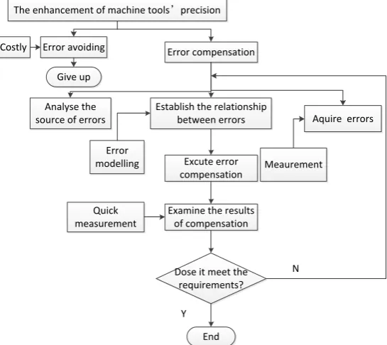
Manufacturing is the mainstay industry for our country, which plays a key role in national economy. As the basic equipment of manufacturing, machine tools attract researchers’ attention to enhance their precision. Generally speaking, there are two ways to achieve above goal. One is error avoiding, which means to avoid bringing in any errors as possible, for example, careful design, perfect manufacture and accurate assembly. However, it leads to huge cost. The other method is error compensation. It imports additional errors to offsets the original errors of machine tools’ system, so it is more economic and convenient. The process of machine tools’ precision enhancement is given as Figure 1.
The enhancement of machine tools’precision
Error avoiding Costly
Give up
Error compensation
Analyse the source of errors
Establish the relationship
between errors Aquire errors
Excute error compensation
Examine the results of compensation Quick
measurement
Dose it meet the requirements?
End Y
N Error
[image:1.595.157.430.424.667.2]modelling Meaurement
Figure 1. The process of machine tools’ precision enhancement.
if the errors are used for compensation, they should be decoupled first which is complex and may bring in some new errors. Thus, the direct measurement is adopted before error compensation and the indirect one is used to check the effect of the compensation.
[image:2.595.182.415.165.289.2]The Sources of Errors
Table 1. The errors deteriorating precision of machine tools.
Machine tool errors
Geometric errors 22% 50%
Thermal errors 28%
Machining process errors
Cutting tool errors 13.5% 35%
Champ errors 7.5%
Thermal errors and
elastic deformation errors of workpiece
6.5%
Operation errors 7.5%
Detection errors
Uncertain errors 10% 15%
Installation errors 5%
There are 3 kinds errors involved in, which are machine tool errors, machining process errors and detection errors, shown in Table 1[1]. From the table, geometric errors account for 22%, which affect the machine tools’ accuracy seriously, so the paper focuses on them.
For a 3-axis machine tool, 21 geometric errors are involved, as follow.
Linear positioning error: δx(x),δy(y),δz(z); Vertical straightness error: δy(x),δx(y),δx(z);
Horizontal straightness error: δz(x),δz(y),δy(x); Roll angular error: εx(x),εy(y),εz(z);
Pitch angular error: εy(x),εx(y),εx(z) ; Yaw angular error: εz(x),εz(y),εy(z);
Squareness errors: Sxy,Syz,Szy
Relationship between Errors—Error Modelling
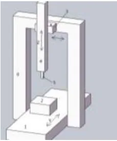
The model depends on the structure of machine tool. Take YTXZ for example, shown as Fig.2, 0 represents the base, 1 is glide board moving along Y-axis, 2 is workpiece, 3 represents the slider running along X-axis, 4 is a column going along Z-axis and 5 is the cutting tool.
[image:2.595.98.213.526.664.2] [image:2.595.341.528.575.659.2]
Figure 2. The structure of the YTXZ machine tool. Figure 3. The principle of laser interferometer for positioning errors.
The structure of the machine tool can be divided into 2 branches, one is the cutting tool branch and the other is the workpiece branch. In the ideal condition, the end of two branches should coincide with each other at the specific point, but it may not happen because of the inevitable errors. The difference between the two branches is the machining error and it can be calculated by Denavit-Hartenberg matrixes and homogeneous transformations. The Denavit-Hartenberg matrixes are used to describe the position feature and error character in the coordinate, for example, 2
w
represents the feature of workpiece in the 2 (workpiece) coordinate system and 5
t
T means the feature of cutting tool in the 5 (cutting tool) coordinate system. However, the above matrixes cannot compare with each other directly, except they are in the same coordinate system, so homogeneous transformations are employed to transform the coordinate system. As the base 0 is the common component of two branches, it is chosen. Therefore, the error model can be given as Eq.1
0 2
01 12
0 5
03 34 45 0 0
w w
t t
w t
T T T T
T T T T T
E T T
(1)
Errors Acquisition –The Principle of the Measurements
The measurements not only work for data collecting to error compensation, but also for quick checking the effect of the compensation. So for the different purposes, the measurements are introduced separately.
The Direct Measurements
The direct measurements for 3-axis machine tool mainly use laser interferometer. The equipment consists of laser source, several interferometer mirrors and reflector mirrors. The principle is as follows.
(1) The principle of collecting positioning errors
Shown as Fig.3, laser beam from the laser head’s launch hole go to the splitter (in the interferometer), which separate it into two beams. One beam goes up to the fixed reflector (in the interferometer), the other beam runs to the mobile reflector. By the reflectors, two beams are both returned back and meet with other at splitter where the interference phenomenon happens. According to the times of interference, the distance L (the mobile reflector moves) can be calculated[2].
(2) The principle of gathering angular errors
The laser beam from laser head goes into the angular interferometer, where the beam is divided into two parts. One goes up then to the angular reflector (Beam A1), while the other keeps straightly to the reflector (Beam A2); Subsequently the two beams return in new paths by the angular reflector and afterwards they converge into one beam at the interferometer which goes back to the laser head. The angular error causes the rotation of the reflector which bring in a change in the path difference, thus the error can be acquired by the change to divide the distance between incident beam A1 and incident beam A2.[3]
(3) The principle of gathering straightness errors
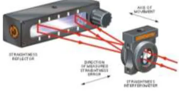
The outgoing beam from the laser passes through the straightness interferometer which splits it into two beams which diverge at a small angle and are directed to the straightness reflector. The beams are then reflected from the straightness reflector and return along a new path to the straightness interferometer as shown in Figure 5. At the straightness interferometer the two beams are converged and a single beam is returned to the entry port in the laser head. The straightness is measured by detecting the optical path change from a relative lateral displacement between the interferometer and the reflector.
[image:3.595.354.538.667.762.2]Figure 4. The principle of laser interferometer for
straightness errors.
[image:3.595.63.283.670.759.2](4) The principle of collecting squareness errors
Squareness measurements are carried out by making straightness measurements along each of the two nominally orthogonal axes of interest, using a common reference; a common reference is required so that the two sets of straightness measurements can be compared and the out of squareness of the two axes calculated. Take horizontal-to-horizontal squareness measurement for example, shown as Figure 6.
[image:4.595.96.508.182.367.2]
(a)First axis’ measurement (b)Second axis’ measurement
Figure 6. The principle of laser interferometer for squareness errors.
The Indirect Measurement
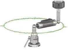
The ball bar is adopted to complete the indirect measurement for machine tool. In theory, if program a CNC machine to trace out a circular path and the positioning performance of the machine was perfect, then the actual circle would exactly match the programmed circle. In practice, the errors can cause the radius of the test circle and its shape to deviate from the programmed circle; the machine tool’s accuracy can be acquired by accurately measuring the actual circular path and comparing it with the programmed path, shown as Fig.7[4].
Figure 7. The principle of the ball bar.
Experiments
[image:4.595.240.357.552.638.2]Experiments by Laser Interferometer
As the measurements for 3 translational axes are similar, in order to avoid repeating, only Y-axis is chosen to be discussed detailed. The setup of laser interferometer for X-axis is given in Fig.8. It costs more than half an hour for each single error’s experiment; in other words, a lot of time should be used to gather all errors by laser interferometer.
[image:5.595.305.519.475.638.2](a) For positioning errors (b) For straightness errors (c) For angular errors
Figure 8. The setup of laser interferometer.
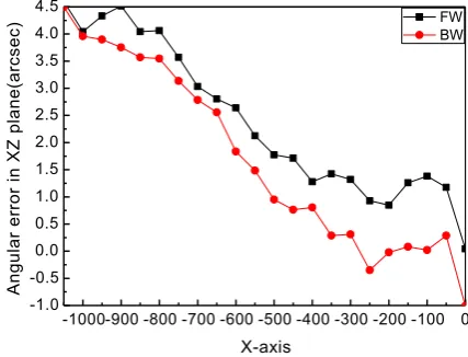
Some representative experimental results for X-axis are demonstrated in Figure 9-11, where are positioning error, angular error in XZ plane and straightness error in the XZ plane, respectively. The X-axis moves from 0 to -1200mm, the positioning error increases continuously, the maximum is 0.16mm, repeatability is 0.004mm and the backlash is 0.001mm. The general trend of the angular error in XZ plane is also growing when X-axis goes from 0 to -1050mm. Its peak value is 5.61 arc-seconds. The straightness error is different, which is not a single trend. The value is 0.01120mm (the negative sign in Figure 11 represents the direction of the error).
-1200 -1000 -800 -600 -400 -200 0
-0.14 -0.12 -0.10 -0.08 -0.06 -0.04 -0.02 0.00
Po
si
tio
n
in
g
e
rro
r(mm)
X-axis
FW-1 BW-1 FW-2 BW-2
-1000-900 -800 -700 -600 -500 -400 -300 -200 -100 0 -1.0
-0.5 0.0 0.5 1.0 1.5 2.0 2.5 3.0 3.5 4.0 4.5
Angular error
in
XZ
plane(arc
sec
)
X-axis
FW BW
-1100-1000-900 -800 -700 -600 -500 -400 -300 -200 -100 0 -0.006
-0.005 -0.004 -0.003 -0.002 -0.001 0.000 0.001 0.002 0.003 0.004 0.005 0.006
St
raight
nes
s
error
in
XZ
plane(m
m
)
X-axis
[image:6.595.195.400.77.227.2]FW BW
Figure 11. Results of straightness error in the XZ plane.
Experiments by Ball Bar
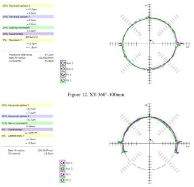
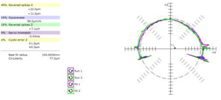
[image:6.595.105.492.383.755.2]Due to the limit of experimental condition, only the length 100mm of bar is selected. In the horizontal plane (XY plane), the machine tool with the ball bar can run a full circle, but in vertical plane, it can rotate approximate semicircle. Circle in XY plane is formed by X-axis and Y-axis associated movement, the result shows in Figure 12. Semicircles in YZ plane and in ZX plane are both from 0 to 220 degree, and their results shows in Figure 13 and Figure 14, respectively. All experiments by ball bar are done in a half an hour.
Figure 12. XY-360°-100mm.
Figure 14. ZX-220°-100mm.
Conclusion
(1) After analyzing the source of errors, the main errors which have significant influence on the accuracy of machine tools are found out.
(2) Based on Denavit-Hartenberg matrixes and homogeneous transformations matrixes, the error model is established, which builds relationship between every single error and compensation.
(3) According to the character of compensation and acceptance’s need, the methods for measurements are introduced. The experiments are done, they validate the feasibility.
Acknowledgement
This research is supported by the Innovation Program of Shanghai Municipal Education Commission under Grant No. 14YZ155; the School Fund of Shanghai Second Polytechnic University under Grant No. EGD16XQD05; the Key Academic Discipline Projects of Mechanic Engineering of Shanghai Second Polytechnic University under Grant No. XXKZD1603
References
[1] Shen Jinhua. Key technique and application in error compensation for CNC machine tools [D]. Shanghai Jiao Tong University. 2008.
[2] AbdulWahid Khan. Calibration of 5-axis machine tools[D]. Beijing: Beihang University. 2010, 48-49.
[3] Authony Co, Yalcin M E. Vertical machining center accuracy characterization using laser interferometer Part I[ J ]. Linear Positional Errors, 10 ( 5) : 394-406(2000).