A NOVEL APPROACH TO GENERATE TEST CASES FOR
COMPOSITION & SELECTION OF WEB SERVICES BASED
ON MUTATION TESTING
1ASHOK KUMAR. P.S
,
2 KAARTHICK .B,
3GOPAL KRISHNA. C1 Assistant Professor, Dept of Computer science & Engineering, YDIT, Bangalore-566078, INDIA 2 Professor & Head, Department of E & C Engineering, VTU, Coimbatore-641047, INDIA 3
Assistant Professor, Dept of Computer science & Engineering, AIT, Chikmagaluru-577101, INDIA E.mail: [email protected] , [email protected] , [email protected]
ABSTRACT
Now a day’s Web Service has become a significant part of the web. The importance of Web Services is to support interoperable and Application – to – Application interaction over a network with proper URI, so that Web Services provide high value to online business transactions. Testing (Verification & Validation) is a critical activity in software product design. Rigorous software testing is not possible so different software testing techniques are invoked before releasing the product. Based on Prim’s algorithm we created all possible test cases from directed weighted graph. Mutation testing is a structural testing method; it generates software tests and evaluating the quality of software testing by fault insertion in original code. A case study has been presented here in order to create the efficacy of our test approach in mutation analysis.
Keywords: Mutants, web service, testing, URI, SRS
1. INTRODUCTION
Web service is a modest and self-possessed modular application. Current trends in performing business-to-business transactions and enterprise application integration (EAI) have been extended to the use of web services. Web services facilitate the incorporation of different business processes [1]. Software testing is a critical activity in the software design and development life cycle, where testing is a collection of quality and creative test cases. Test cases are directly mapped through workflow of a system. Test cases are derived from SRS (system requirement specification) of a system accepted by the user. For reusability of a system, patterns are most important, based on Patterns tester will create test cases. Since exhaustive testing is usually not traceable, test strategies are faced with a problematic task that is how to detect a minimum set of test cases that is sufficiently effective for revealing potential faults in a program. If the system design and Architecture is clear and complete, then test cases are created before the development cycle has been started and ready to test the system based on test cases. If the test cases are created earlier than the development
phase, then the development team will find ambiguities (or unclearness) in the SRS and design documents [2][4].
In testing process a mutation is a small change in a program; such small changes are intended to model low level defects that arise in the process of coding systems. The mutation testing is a fault based testing strategy that measures the quality of testing by examine whether the test set, test input data used in testing can reveal certain type of faults, i.e. we use the structure of the code to guide the test process and estimating the number of faults present in systems under test [5].
Mutation testing methods generates simple syntactic deviations, mutants of the original program representing typical programming errors such as a mutation methods replaces an arithmetic operator like ‘+’ with -, *, / which is intended to represent the programmer using a wrong operator.
notations for modeling and design object-oriented systems (OOMD). It has various set of diagrams for representing the dynamic behavior of objects in a system.
Main intension of our work is to creating test cases based on UML collaboration diagram generated by the design specification of the system. UML collaboration diagram represents the interaction between objects with a sequence of operation [7][8] . Section 2 describes the related work & description of Testing. Section 3 defines the composition of web services approaches. Section 4 states the recommended methodology and usage of our system. Section 5 demonstrates the Case study – Bill payment system in Roopa’s
mall. Section 6 deals with design and
implementation of Mutation testing in web services application, where Tests are created and measured based on the basis of their fault insertion techniques. Section 7 explain the conclusion briefly.
2. RELATED WORK
In web services research arena, the mutation testing has a rich history and it focuses on three kinds of activities in testing process, like
1) Defining mutation operators, 2) Experiment,
3) Development tools.
The first one involves defining new mutation operators for different languages and types of testing.
Mutation testing is a fault based technique, it conforming to different programming languages or types of the applications. It is an efficient method to assess the quality of a given test suite, also limitations do exist. The most common problems are represented by the increased computation time, necessary to derive the entire mutation testing process, and the equivalent mutants problem [5].
The second research activity performing the experiment with mutations. An empirical study in mutation testing has been allowed the testing process is creative and competent manner. Mutation testing approach is more powerful than different testing approaches, like statement coverage, branch coverage, path testing, etc, but Mutation testing is more effective in finding faults than data flow [10].
With respect to web services research, the third kind of activity is mutation development tools, Jester, Jumble, MuJava, JavaMut are dedicated java mutation development tools.
In Roop’s Mall bill payment system, the web services use ontology to enrich the linking between resources and Object-ontology mapping. Here some of the approaches are developed with respect to my research projects, which can be considered as a motivation and inspiration of my recent research work.
3. COMPOSITION APPROACH IN WEB
SERVICES
In SOA, the composition of web services can perform all potential operations within an information system. The composition operations facilitate the application into very complex descriptions of web service capabilities within an application. The service discovery mechanism depends on service descriptions. Service discovery is normally limited to matching of service inputs and outputs [2].
The implication of Composition of Web service is to find effective all possible activities in the web services application. Composition of web service is totally based on services that are considering on available input data, i.e. these services are specified by the user query. In the initial state of composition of web services we do not know which services to be considered or which are not required. Actually we realize all available services to be enabled from User end or we mark usable as input data for a service. The significance of serviceable activity is to specify all serviceable activities and build the composition of services available from input data. The implication of finding unserviceable activity is to restrict the set of services which are considered during the composition.
For Instance, to Order a ‘LENOVO Laptop’ through online web services can be represented in mathematical form as,
A web method is an Order set of activity; this can be represented as grammar style notations,
Let
a
1, a2, a3……… a
n be the set of input dataLet
b
1, b
2, b
3……… b
n be the set of output data,P = (A Ụ B) = > ({a1, a2, ..an } Ụ { b1, b2, ..bn})
assume
a
’s means input,b
’s means output are the subset of K, for homogeneous relation can be written as P(K) Order_ LENOVO Laptop can be written as –LENOVO Laptop =
{av, spec, pr, dd, dp} → Order_Laptop
LENOVO Laptop low-end = {av, spec, Pr, dd, dp}
LENOVO Laptop I5 = {av, spec, Pr, dd, dp,
ospec}
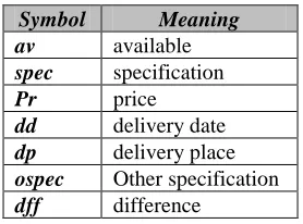
[image:3.612.124.263.342.445.2]Attribute list resulting entity of the low-end and high-end LENOVO Laptop can be written as,
Table 1: Entity Attribute List
Symbol Meaning
av available
spec specification
Pr price
dd delivery date
dp delivery place
ospec Other specification
dff difference
To order an LENOVO Laptop can be defined as, Laptop order = dff {Laptop low-end , Laptop I5 }
Different operations in composition of web services are,
1. Selection or Event composition 2. Sequential composition
In theory a Union describes the selection or choice of two or more web methods or simple web services,
i.e.
Laptop order = dff {Laptop low-end , Laptop I5 }
The sequential composition of web services is a two ordered pair values of web services, like ws1, ws2
Where, ws1 = (a, b) and ws2 = (x, y)
Sequential composition of web services can be defined as,
{(a, b), (x, y)} = {ws1, ws2} then,
{ws1, ws2} = dff
Composition of two relations A and X can be defined as,
{ws1, ws2} = {A: B} then, {A: B} can be written as,
{A: B} = dff {a:b | a A,
x X, (a:x) are defined }
i.e. size of output set ‘a‘ as the same size of input set ‘x‘
4. RECOMMENDED SYSTEM
METHODOLOGY
Steps involved in this proposed methodologies are, 1.Study the system and deduce that SRS is
accepted by the user?
2.Design and develop collaboration diagram using Smart Draw software and save the file name as XYZ.srd extension
3.Transfer the collaboration diagram into graph. 4.A graph is a collection of vertices or nodes and
edges, where
i. Nodes are represented by objects ii. Edges are represented by information 5.Information weights are represented as sequence
of number between two nodes.
6.Using Prim’s algorithm to find the minimum weighted node.
7.Finding the Test sequences based on node traversal in the graph.
Figure1: Control Flow Of Proposed System Methodology
Figure 1 represents the Control flow of recommended System methodology. The testing process of our case study Bill payment system in Roopa’s mall, we introduced Mutation Testing. Once we get Mutation score we transfer that report into test team and find the implications with SRS and test result.
5. EXPERIMENTAL INFORMATION
With respect to Customer view –
• Our product is a final product for Bill payment system in Roopa’s Mall itself, but it is not developed for end users or other customers.
• Our product is totally developed for select & composing of online items or product billing system in mall.
Below Algorithm is specifying to find the minimum weighted node in a collaboration diagram used in our case study – Bill Payment System in Roopa’s mall.
Prim’s Algorithm to find minimum weighted node,
input: G, V, F
output: find minimum weighted node
for ( int i=0 ; i= lvl ; i – –) destination [i] = ∞ edges [i] = null;
while (F is a vertex)
for(each vertices v=v1, v2)
if(length (v1, v2) < distance [v2]) distance [v2] = length (v1 , v2) edges [v2] = v1
end if end for
end while end for
5.1 Case Study: Bill Payment System in Roopa’s Mall
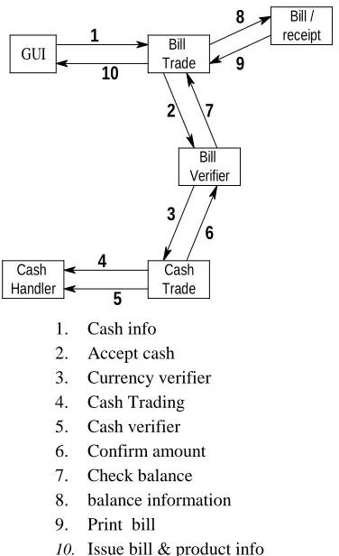
In Roopa’s mall bill payment system, cashier gets the cash from customer and returns the balance and receipt or bill to customer. A bill should contain whole information about the products purchased by customer with price on unit or item wise. The collaboration diagram of this system represents the entire functions of this case study. The system has major live components like: GUI, Trade Bill, Bill verifier, Cash Trade, Cash Handler and Bill/ receipt. The entire Roopa’s Mall bill payment system has been represented in the form of a collaboration diagram.
GUI
Bill Verifier
Bill / receipt
1
3 6
10 9
8
7 2
4
5
Bill Trade
Cash Trade Cash
Handler
1. Cash info 2. Accept cash 3. Currency verifier 4. Cash Trading 5. Cash verifier 6. Confirm amount 7. Check balance 8. balance information 9. Print bill
[image:4.612.326.514.395.703.2]10. Issue bill & product info
When customer expects a bill in the bill counter, cashier will edit all the merchandised products through GUI. The dash board of bill GUI will automatically generate the product price with respect to the number of units, that will take care of bill transact. Bill verifier will verify the bill information with price details. GUI will provide full information about the mall, even though what are the facilities, offer, discounts and different products are available within the mall as well as the unit price of the product and merchandised product information. The cash transact gives cash confirmation acknowledgement and balance information to bill transact. Bill transact sends an acknowledgement to GUI. Finally bill transact will issues a bill to customer.
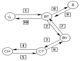
5.1.1 Collaboration diagram to weighted graph
After design and develop the collaboration diagram using Smart Draw software and save the file as XYZ.srd, then pass this file as input to the parser [11]. The parser collects all the information about objects and statements, which are represented as nodes and edges in a directed graph with weights shown in figure 3.
Figure 3: Conversion Of Function In Collaboration Diagram To Directed Graph
A directed graph is a non-linear data structure, where each and every edge are directed, which can be represented in mathematically as,
[image:5.612.343.518.111.225.2]
The Mapping of objects in collaboration model to its corresponding auxiliary node in a directed graph can be represents in Table 2.
Table 2: Mapping Info Table Of Objects
Objects in collaboration model
auxiliary node
GUI G
Bill Trade BT
Bill Verifier BV
Cash Trade CT
Cash Handler CH
Bill B
[image:5.612.332.471.296.440.2]The mapping information of contents in collaboration model and weights with respect to an edge in a directed graph is represented in Table 3.
Table 3: Mapping Information Weight And Contents
contents in collaboration model
Weights
Accept cash 2
balance information 8
Cash info 1
Cash trading 4
Cash verifier 5
Check balance 7
Confirm amount 6
Currency verifier 3
Print bill 9
Issue bill 10
[image:5.612.109.283.440.571.2]Figure 3 represents the mapping information for weight and contents in collaboration diagram graph for bill payment system.
Figure 4: Mapping Information For Weight And Contents Graph
[image:5.612.334.512.492.621.2]Table 4: Test Case Sequence Of Bill Payment System
test sequence of graph
Spanning tree <G-1-BT> valid <BT-2-BV> valid <BV-3-CT> valid <CT-4-CH> valid <CH-5-CT> valid <CT-6-BV> valid <BV-7-BT> valid <BT-8-B> valid <BT-9-B> invalid <BT-10-G> invalid
<G-1-BT-2-BV-7-8-B-9-BT-10-G> terminated
6. MUTATION TESTING IN WEB
SERVICES APPLICATION
Mutation testing is a white-box fault-based technique, it measures the effectiveness of test set for fault localization, where test set should kill all the mutants, i.e. mutation is a low-level defect creation technique. The main importance of mutation testing is to measure the effectiveness of test sets in discovering defects [13].
6.1 Fault Insertion
Test cases are created using Prim’s algorithm for the testing process of Bill payment system. Mutations will define good test sets are comprised in test process. In the concept of Fault insertion approach, we introduce a `defect’ or ‘bug' by altering a program and observing that, if our `mutated program' acts different to the original program with respect to any element of the test set [10].
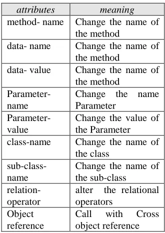
For the mutation analysis process table 3 represents the parameters list of collaboration diagram. For bill payment system we created 90 mutants are shown in table 6 and different attributes and their descriptions of a bill payment systems are represented in table 6.
Table 5: Attributes And Their Meaning
attributes meaning method- name Change the name of
the method
data- name Change the name of the method
data- value Change the name of the method
Parameter-name
Change the name Parameter
Parameter-value
Change the value of the Parameter class-name Change the name of
the class
sub-class-name
Change the name of the sub-class
relation-operator
alter the relational operators
Object reference
Call with Cross object reference
If a test set is good, it kills all mutants i.e. alter the operators in program [5].
[image:6.612.336.501.113.346.2]For example, in a mutated program, if I found ADD sign (+) that can be replaced by any one of operators like, (- ,*, /).
Figure 5: Equivalent Mutant
[image:6.612.314.521.441.478.2]Figure 5 represents an example, of an Arithmetic Operator Replacement (AOR) mutation. It is important to detect and avoid equivalent mutants because it causes low mutation score, and mutants cannot be killed.
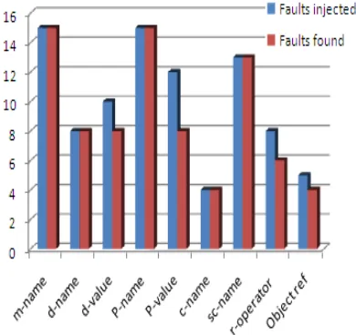
Table 6: Mutants Summary Of The Bill Payment System
Test parameters Faults injected
Faults found
method- name 15 15
data- name 8 8
data- value 10 8
Parameter-name 15 15
Parameter-value 12 8
class-name 4 4
sub-class-name 13 13
relation-operator 8 6
Object reference 5 4
[image:6.612.330.517.578.733.2]6.1.1 Mutation test score
A mutation score is a quantitative measurement of the quality of the test set. Mutation score can be defined as a percentage in the ratio of the number of killed mutants to the total number of equivalent mutants. The total number of non-equivalent mutants results from the difference between the total number of mutants and the number of equivalent mutants. Equivalent mutants always produce the same output as the original program, so they cannot be killed.
Mutant/Mutation score can be also computed for the entire Test set -
Mutation score M can be defined as,
Figure 6 represents the graph of mutation analysis about Faults Injected and Faults Found for bill payment system.
Figure 6: Mutation Testing Graph
7. CONCLUSION
Our agile methodology is well suited for generating sufficient test cases for UML Collaboration diagram. In our case study Roopa’s
Mall Bill payment system, we tested application by
traversing a directed graph through prim’s algorithm. Mutation testing is a complicated and computationally expensive testing methodology. Mutation testing is not a replacement for code coverage, but it is a complementary approach, i.e. it is useful in detecting those pieces of the code,
when faults are injected, but it is not actually full testing approach. For mutation testing we have clear understanding of system requirement specification and different features of Java. From our experiment we concluded that our methodology is useful to detect errors at an early stage in the development life cycle.
REFRENCES:
[1] J. D. McGregor, and D. A. Sykes, “A Practical Guide to Testing Object-Oriented Software “, Addison Wesley, NJ, 2001.
[2] Binder, R. V. Testing Object-Oriented Systems: Models, Patterns, and Tools. Addison-Wesley, 2000.
[3] R.V.Binder, Testing object-oriented software: a survey. Software Testing Verification and Reliability, 6(3/4): 125-252, 1996.
[4] UML Specification, http://www.omg.org/ technology/documents/formal/uml.htm. [5] Booch, J. Rumbaugh and I. Jacobson:
“Unified Modeling Language User Guide”. Addition-Wesley, 1999.
[6] K. BARCLAY, J.SAVAGE, Object-Oriented Design with UML and Java, Elsevier, 2004, [7] S. K. Swain. UML-based Testing of Software
System, Technical Report, KIIT, 2005. [8] Prasanna M, Chandran K R, Thiruvenkadam
K. Automatic Test Case Generation for UML Collaboration Diagrams. IETE J Res 2011;57:77-81
[9] Puneet Patel1 and Nitin N. Patil2, Test case formation using UML activity diagram , World Journal of Science and Technology 2012, 2(3):pp. 57-62
[10] J. Hartmann, M. Vieira, H. Foster, and A. Ruder., “A UMLbased approach to system testing. Innovations in Systems and Software Engineering”, 1(1):12-24, April 2005. [11] Debasish Kundu and Debasis Samanta., “A
Novel Approach to Generate Test Cases from UML Activity Diagrams.”, Journal of Object Technology Vol. 8, No. 3, May/June 2009 [12] L. Briand and Y. Labiche., “A UML-based
approach to system testing.” In 4th International Conference on The Unified Modeling Language, Modeling Languages, Concepts, and Tools, pp. 194-208, 2001.
[image:7.612.94.289.384.568.2]