EDCA LIMITATION WITH HIGH TRAFFIC REAL TIME
APPLICATIONS
1AHMED ABU-KHADRAH, 2ZAHRILADHA ZAKARIA, 3MOHDAZLISHAH OTHMAN
1,2,3
Centre for Telecommunication Research and Innovation (CeTRI), Faculty of Electronic and Computer Engineering, Universiti Teknikal Malaysia Melaka (UTeM), Hang Tuah Jaya 76100 Durian Tunggal
Melaka Malaysia E-mail: 1
ABSTRACT
The simplicity of expanding and maintenance wireless network helped to use it widely in the public locations such as parks, airports and bus stations. Distributed Coordination Function (DCF) and Enhanced Distributed Channel Access (EDCA) protocols are used with WLANs. DCF protocol sends its data without any priority between different data types, and does not give any advantage of real time application such as voice over internet protocol (VOIP) or video conference. However EDCA protocol divides data to different class’s voice, video, best effort and background. Each class has its own priority and parameters. The default values of EDCA protocol give voice traffic the highest priority. Quality of Service (QOS) parameters such as end to end delay, packet loss and jitter values determine if the protocol support QOS or otherwise. This paper evaluates the performance of DCF protocol and EDCA protocol by using OPNET simulation and shows the differences between them, depending on QOS parameter values. The result of simulation shows the limitation of EDCA protocol when increasing the number of VOIP users. Therefore the EDCA protocol tolerates specific number of real time applications with acceptable values of QOS parameters.
Keywords: DCF, EDCA, QOS
1.
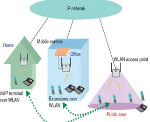
INTRODUCTION [image:1.595.330.485.461.587.2]The wireless network was spread in the world; it is used at homes, offices and also in the public locations such as airports, restaurants and bus stations. Nowadays the increment of using smart phones that have many wireless applications increased the concern to enhance the performance of wireless networks. The real time applications such as voice over internet protocol (VOIP) and video conference consider the real challenge for WLAN, because these applications need restrict time to reach destination and specific percentage of packet loss that can tolerate it. So the WLAN must support QOS to success when using real time application [1]. This means the end to end delay must be less than 150 ms and the percentage of packet loss does not increase than 1% [2]. The prevalence of the internet in all fields of the life and low cost of it make the VOIP application more common, Figure 1 describes how VOIP applications work in different locations.
Figure 1: Using VOIP in different location.
There are some differences between wired and wireless networks. The wireless networks have more overhead packet and limitation in bandwidth rather than wired networks. In addition to that the weather and the size of wall inside building also affect to the efficiency of wireless networks [3].
effort service without any priority between different types of data [5]. However EDCA protocol divides data to four access categories depending on the types of data.
In this paper, we propose the difference between the DCF and EDCA protocol as well as evaluating how the ECDA protocol supports QOS with less delay and packet loss. The limitation in the EDCA protocol when increasing the real time application users will also be determined.
2.
DCF PROTOCOLIEEE802.11 uses DCF protocol, which depends on Carrier Sense Multiple Access Collision Avoidance mechanism CSMA/CA [6]. There are two ways to send data in DCF protocol, the first one basic way method and the second request to send (RTS) and clear to send (CTS) method.
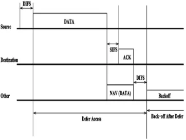
[image:2.595.308.488.445.601.2]In the basic method the station senses the medium if it is idle or not after Distributed Inter Frame Space (DIFS) time. If the medium is free, the station start sends its data and reserved the medium. In this case all stations in the network set the Network Allocation Vector (NAV), which means the medium is reserved. If another station tries to send at this time it will be deferred and takes backoff time which calculated randomly to avoid collision. When the data reach destination, it wait Short Inter Frame Space (SIFS) and sends the acknowledge (Ack) to the sender [7]. Figure 2 illustrates how basic method in DCF protocol works.
Figure 2: Basic method of DCF.
The RTC/CTS method is used with DCF protocol to avoid collision and solve the hidden node problem. This problem happens when a network has more than one access point and there
are interferences between the ranges of the access points. The basic method of DCF does not solve this problem because all stations unable to hear each others in different access point ranges, but when using RTS/CTS method the hidden node problem will be solved [8]. With RTS/CTS method the station that requires sending data, senses the medium after DIFS time to check if it is idle or not. If it is idle it sends RTS to the destinations per requirement. Then the destination sends CTS after SIFS time when it is free, therefore by this mechanism all the stations in the network heard each other’s and avoid the hidden node problem, as it is shown in Figure 3. If the station senses the medium busy, it will take backoff time that calculates randomly depending on the contention window minimum and maximum size (CWmin,CWmax). By using Eq. 1, the backoff time can be calculated. At the first collision the integer random value selects from [0,CWmin]. If the collision happens again the CW will be duplicated until reach CWmax [9].
Backoff time= random() ×Slot Time (1)
[image:2.595.94.275.543.679.2]Where random() is integer value between [0,CW] and CW between[CWmin,CWmax].
Figure 3: RTS/CTS method.
3.
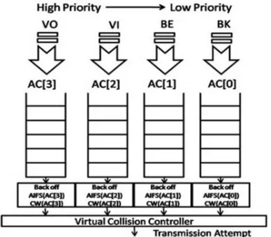
EDCA PROTOCOLits data faster than other types. In the default EDCA priority the voice data takes the highest priority which makes it has less delay and packet loss. Figure 4 describes how EDCA protocol divides data to four classes depending on the types of the data. EDCA also gives each AC different parameters than others. The parameters are Contention Window (CW), Arbitration Inter Frame Space(AIFS) and Transmit Opportunity Length (TXOP) [11].
Table 1: Default Priorities For EDCA Protocol
Priority Access
Category
Designation
1 AC_BK Background
2 AC_BK Background
0 AC_BE Best Effort
3 AC_BE Best Effort
4 AC_VI Video
5 AC_VI Video
6 AC_VO Voice
7 AC_VO Voice
CW parameter is used to calculate the backoff time by selecting the random value between [1, CW]. The first value of CW sets to CWmin for the first transmission [12]. If the collision happens again the CW will increase until reach CWmax. The difference between DCF and EDCA is CWmin and CWmax have different values for each AC in EDCA protocol, but DCF protocol has only one value of CWmin and CWmax [13].
Figure 4: EDCA Access Categories And Priorities.
The second parameter, AIFS is used to determine the priority of the AC’s. It is the amount of time that waits until sense the medium or start count down the backoff counter. By changing the AIFS
value for each AC it will cause different priority between AC’s. Figure 5 shows how changing the values of the AIFS leads to different priorities [14]. According to figure (5) the voice takes the lowest value. That means needing less time transmit its data. The AIFS can be calculated depending on the AIFSN value which represents the number of slot time after the SIFS [15]. Eq. 2 explains how the AIFS is calculated.
AIFS[AC]=SIFS+AIFSN[AC]×Slot Time (2)
[image:3.595.313.493.355.488.2]The third parameter, TXOP represents the maximum duration time to reserve the medium. The high value of the TXOP means the higher priority [9]. In general all three parameters CW, AIFS and TXOP affect to the priority for AC but the AIFS plays the important factor to determine the priority. In addition to that, when decreasing, the backoff time will decrees also.
Figure 5: How AIFS Determine Priorities.
4.
SIMULATION RESULTS ANDDISCUSSION
4.1 Scenario1
[image:3.595.89.283.504.674.2]Figure 6: Scenario 1 Components.
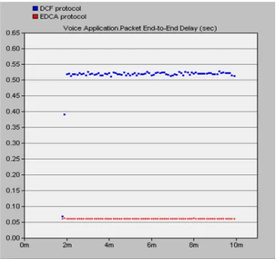
[image:4.595.88.295.106.311.2]In the first we want to measure the end to end delay for both DCF and EDCA. End to end delay counts the waste time when the sound comes out from sender until reach the receiver. The value of end to end delay must be less than 150 ms to support QOS. Figure 7 shows the difference between DCF and EDCA protocol for end to end delay when sending voice application.
Figure 7: End To End Delay For Voice Application In Scenario1.
According to Figure 7 the end to end delay when using DCF protocol is 0.512 second, but when using EDCA protocol it becomes 0.0608 second. Depending on these results the EDCA protocol supports QOS because the value less than 150ms.
Figure 8 presents the number of receive packets when sending 100 packets /second. From this value the packet loss can be calculated. The packet loss is
[image:4.595.308.499.240.408.2]caused by contentions inside the network; therefore some packets do not reach the destination. To support QOS the percentage of packet loss must not increase than 1%. According to the Figure 8 the packet loss for voice application when using the DCF protocol is 4.16%, but when with the EDCA protocol it is 0.004%. These results describe how the EDCA supports QOS because the value less that 1%.
Figure 8: Traffic Received For Voice Application In Scenario1.
[image:4.595.89.284.434.616.2]The difference time between arriving packets is called jitter; Figure 9 shows the values of jitter when using EDCA protocol and DCF protocol. In addition to that, it describes how the jitter decreases when using EDCA protocol.
Figure 9: Jitter For Voice Application In Scenario1.
[image:4.595.308.500.493.665.2]send its data first. The besteffort and background data can tolerate more delay than real time application. So with DCF protocol the end to end delay and the packet loss will increase and do not support QOS. However EDCA protocol divides data to different AC’s depending on the types of data and gives each AC specific value of EDCA parameters to determine the priority. The voice application has the highest priority, so the voice recorded less end to end delay about 0.0608 second and less packet loss about 0.004%.
4.2 Scenario2
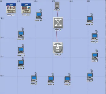
[image:5.595.306.501.308.462.2]In this scenario we design wireless network using EDCA protocol only. There are eleven wireless nodes, one access point and one server. As in scenario1 we define three traffic voice, best effort and background. We also applied the applications on the nodes as in scenario1, except adding one wireless node (node_17) with voice, besteffort and background traffic. The main different between scenario1 and scenario2 is the scenario2 has seven nodes use voice application but scenario1 has six nodes. Figure 10 shows the components of scenario2.
Figure 10: Scenario 2 Components
[image:5.595.89.273.419.582.2]In scenario2 we want to measure the QOS parameters and concern on end to end delay and packet loss. After increasing the number of nodes that use the voice application, the average of end to end delay becomes 0.5188 second and the average of packet loss is 14.62% according to Figure 11 and Figure 12.
Depending on these results, EDCA protocol has limitations when increasing the number of voice or video applications. This means when the numbers of real time application increase, the internal and
external collision will rise and lead to high values of end to end delay and packet loss. So there is a limitation when used EDCA protocol with real time application because EDCA can tolerate a specific number of voice and video applications in the same network.
The default values of EDCA protocol parameters lead to increase the number of internal collisions because these values do not change depending on the situation of the network. Nowadays, researchers are trying to enhance the EDCA protocol by adjusting the contention window values depending on the number of collisions inside the networks.
Figure 11:End To End Delay For Voice Application In Scenario 2.
Figure 12:Traffic Received For Voice Application In Scenario2.
5.
CONCLUSION [image:5.595.306.502.494.665.2]the DCF protocol, the end to end delay and packet loss will increase and therefore it will not support QOS. In contrast, when using EDCA protocol with real time application, the end to end delay, jitter and packet loss support QOS as it is shown in scenario1. It is because the EDCA protocol divides data to different classes and gives the voice the highest priority.
But the numbers of real time application users affect the QOS parameters as it is presented in scenario2. According to the results of scenario2, the end to end delay and packet loss do not support QOS. So there is a limitation in EDCA protocol caused by increasing the collision inside the network. EDCA parameters such as CW and AIFS are fixed for each access category, and trying to make these values flexible depending on the number of collisions inside network may solve this limitation.
REFERENCES:
[1] K. Kosek, M. Natkaniec, L. Vollero, and A. R. Pach, “An Analysis of Star Topology IEEE 802 . 11e Networks in the Presence of Hidden Nodes,” Information Networking, 2008. ICOIN
2008. International Conference on. IEEE, pp.
1–5, 2008.
[2] J. Fitzpatrick, S. Murphy, M. Atiquzzaman, and J. Murphy, “Evaluation of VoIP in a Mobile Environment using an end-to-end Handoff Mechanism,” 2007 16th IST Mobile and
Wireless Communications Summit, pp. 1–5, Jul.
2007.
[3] D. G.V, B.R.Prakash, and B. Prakash, “Performance improvement using adaptation of the contention window in IEEE802.11e WLAN,” World Journal of Science and
Technology, vol. 2, no. 5, pp. 10–14, 2012.
[4] G. R. Hiertz, D. Denteneer, S. Max, R. Taori, J. Cardona, L. Berlemann, and B. Walke, “IEEE 802.11 s: the WLAN mesh standard,” Wireless
Communications, IEEE, no. February, pp. 104–
111, 2010.
[5] F. U. Ahemd and S. K. Sarma, “QoS and Admission Controller in IEEE 802.11e WLAN,” 2013 4th International Conference on
Intelligent Systems, Modelling and Simulation,
pp. 468–471, Jan. 2013.
[6] T. Sugimoto, N. Komuro, H. Sekiya, S. Sakata, and K. Yagyu, “Maximum throughput analysis for RTS/CTS-used IEEE 802.11 DCF in wireless multi-hop networks,” International
Conference on Computer and Communication
Engineering (ICCCE’10), vol. 3, no. May, pp.
1–6, May 2010.
[7] G. Sharma, A. Ganesh, and P. Key, “Performance analysis of contention based medium access control protocols,” Information
Theory, IEEE Transactions, vol. 55, no. 4, pp.
1665–1682, 2009.
[8] S. Ray, D. Starobinski, S. Member, A. The, and R. T. S. Cts, “On False Blocking in RTS / CTS-Based Multihop Wireless Networks,” Vehicular
Technology, IEEE Transactions, vol. 56, no. 2,
pp. 849–862, 2007.
[9] A. Hamidian and U. Körner, “An enhancement to the IEEE 802.11e EDCA providing QoS guarantees,” Telecommunication Systems, vol. 31, no. 2–3, pp. 195–212, Mar. 2006.
[10] R. Bolla, R. Rapuzzi, and M. Repetto, “On the Effectiveness of IEEE 802 . 11e Implementations in Real Hardware,” Wireless Communication Systems, 2009. ISWCS 2009.
6th International Symposium on. IEEE, 2009,
pp. 303–307, 2009.
[11] W. Lai and E. Liou, “A novel cross-layer design using comb-shaped quadratic packet mapping for video delivery over 802 . 11e wireless ad hoc networks,” EURASIP Journal on Wireless
Communications and Networking, pp. 1–28,
2012.
[12] A. Gupta, P. S. Patheja, and N. Raza, “NOVEL CHANNEL ACCESS METHOD IN WIRELESS SENSOR NETWORK USING CSMA / CA,” Asian Journal of Computer
Science & Information Technology, vol. 10, pp.
129–132, 2013.
[13] P. Serrano, A. Banchs, P. Patras, S. Member, A. Azcorra, and S. Member, “Optimal Configuration of 802 . 11e EDCA for Real-Time and Data Traffic,” Vehicular Technology,
IEEE Transactions, vol. 59, no. 5, pp. 2511–
2528, 2010.
[14] M. T. Koprivica, M. M. Ili, A. M. Neškovi, and N. J. Neškovi, “An Empirical Study of the EDCA QoS Mechanism for Voice over WLAN,” Telfor Journal, vol. 3, no. 1, pp. 3–8, 2011.
[15] C. Huang, W. Liao, and S. Member, “Throughput and Delay Performance of IEEE 802 . 11e Enhanced Distributed Channel Access ( EDCA ) Under Saturation Condition,”
Wireless Communications, IEEE Transactions,