tion of its products in the manner described herein will not infringe on existing or future patent rights, nor do the descriptions contained herein imply the granting of license to make, use, or sell equipment constructed in accordance with this description.
Digital believes the information in this publication is accurate as of its publication date; such information is subject to change without notice. Digital is not responsible for any inadvertent errors.
The following are trademarks of Digital Equipment Corporation: CTS-300, DATATRIEVE, DEC, DEC, DECnet, DECservice, DIBOL-83, the Digital logo, DSM-ll, FMS, FORTRAN IV, Internet, LA, Letterprinter 100, Letterwriter 100, MicroPDP-ll/23, MicroPDP-ll/73, MicroPower/Pascal, Micro/RSTS, Micro/RSX, MicroVAXI, MicroVMS, Packetnet, PDp, Professional, Q-bus, Rainbow, ReGIS, RSTS, RSX, RT, ULTRIX, UNIBUS, VAX, VAXELN, VMS, VT.
This handbook was produced by Digital Equipment Corporation, Corporate Communications Group, 200 Baker Avenue, West Concord, Massachusetts 01742.
Chapter 1 • Microsystems Family Overview
Definition of Microsystems ... 1-1 Markets/Applications . . . .. 1-1 Number of Users . . . 1-1 Commonality Among the Microsystems ... 1-2 Q-bus . . . 1-2 System Hardware . . . 1-2 System Options . . . 1-2 Networks . . . 1-2 Differences Among the Microsystems ... ... 1- 3 Central Processors . . . 1-3 System Software . . . 1-4
Chapter 2 • System Hardware
LA50 Printer ... 3-25 LAIOO Printing Terminal . . . .. 3-26 LAl20 Printing Terminal . . . .. 3-27 LA210 Printer ... 3-28 LA12 Printing Terminal. . . . .. 3-29 LQP02 Letter-quality Printer ... 3-30 LQP03 Letter-quality Printer . . . .. 3-30 LN03 Laser Printer ... '.' ... 3-32 DF02 and DF03 Modem Units ... 3-32 DFIOO Modem Enclosure ... 3-34 Additional Documentation ... 3-35
Chapter 4 • System Software and Layered Products
VAX TDMS (Terminal Data Management System) ... 4-24 Productivity Tools . . . 4-24 VAX DEC/CMS (Code Management System) ... 4-24 DECmail-ll . . . 4-24 VAX DEC/MMS (Module Management System) . . . .. 4-24 VAX DEC slide . . . 4-25 VAX DEC/Test Manager . . . " 4-25 VAX DEC/Shell . . . 4-25 FMS (Forms Management System) . . . 4-25 INDENT . . . .. 4-26 MENU-ll . . . 4-26 Communications Software . . . .. 4-26 Additional Documentation . . . 4-27
Chapter 5 • Networks
Introduction . . . 5-1 Types of Systems . . . 5-1 Standalone Systems . . . 5-1 Network-connected Systems . . . .. 5-3 Digital Network Architecture ... , ... 5-5 DNA Structures . . . 5-5 Typical Network Configurations . . . 5-7 Types of Links ... " . . . 5-10
Ethernet Link . . . 5-10 Asynchronous Links . . . .. 5-14 Synchronous Links . . . .. 5-17 Network Software . . . 5-21 DECnet Communications . . . 5-21 Internet Communications . . . " 5-22 Packet net System Interface . . . .. 5-22 Single-user System Connection . . . 5-24 Additional Documentation . . . 5-24
Chapter 6 • Architecture Summary
Registers and Stacks. . . . .. 6-11 MicroVAX Registers . . . 6-12 MicroVAX Program Counter . . . 6-13 MicroVAX Stack, Argument, and Frame Pointers ... 6-.13 Micro VAX Processor Status Longword . . . .. 6-14 MicroPDP-ll Registers . . . 6-14 Processor Status Word . . . 6-15 Addressing Modes . . . .. 6-17 Micro VAX Addressing Modes . . . 6-18 MicroPDP-ll Addressing Modes . . . 6-19 Exceptions and Interrupts . . . 6-21 Exception and Interrupt Vectors . . . 6-21 Processor-priority Levels. . . . .. 6-22 Context Switching . . . 6-22 Processor Operating Modes . . . .. 6-22 MicroVAX Operating Modes . . . 6-23 MicroPDP-ll Operating Modes . . . 6-24 Data Types . . . 6-24 Instruction Sets . . . 6-28 MicroVAX Instruction Set . . . 6-28 MicroPDP-ll Instruction Set . . . 6-29 Microsystem Instruction Set Summary . . . 6-30 Additional Documentation . . . 6-44
Appendix A • Q.bus . . . A-1
Appendix B • PDP.ll/23-PLUS Overview . . . B-1
Appendix C • Site Preparation and Installation . . . C-1
Appendix D • Customer Services . . . .. D-1
Appendix E • Documentation . . . . . . .. E-1
Appendix F • MicroPDP-ll/SV Overview . . . F-1
Glossary . . . Glossary-1
This Microsystems Handbook is a concise reference for Digital's 16-bit and 32-bit supermicrocomputers. It describes the functions of each member of the microsystems family-the MicroVAX I, MicroPDP-ll/73, and MicroPDP-ll/23-and their related options MicroPDP-ll/23-and software.
Chapter 1 provides afamily overview with sections describing the similarities and differences among the various microsystems.
Chapter 2 outlines the basic hardware components of the family along with the types of configurations that are available.
Chapter 3 explains each of the system options that are available. These include memory, performance options, storage devices, communications devices, terminals, and printers.
Chapter 4 outlines basic system software products for the microsystems, including operating systems, high-level languages, information management products, productivity tools, and communications software.
Chapter 5 describes the Digital Network Architecture and how the microsys-tems implement the architecture with such products as DEe net, Ethernet, Internet, and Packetnet.
Chapter 6 summarizes the VAX and PDP-ll architectures and how they are implemented in the MicroVAX I and the MicroPDP-ll systems.
Appendix A gives a technical description of the 22-bit Q-bus that is the backbone of the microsystems family.
Appendix B gives general information on the PDP-ll/23-PLUS, the original Q-bus PDP-ll system.
Appendix C provides help with the preparation for the microsystem installation and gives some configuring guidelines.
Appendix D covers Digital's extensive Customer Services programs.
Appendix E lists additional reference documentation for MicroVAX I and MicroPDP-ll hardware and software.
Your comments and suggestions will help us in our continuous effort to improve the quality and usefulness of this handbook. Please complete and return the Reader Comment Sheet that can be found at the back of this book.
Note
Digital's microsystems are a family of low-cost, medium-to high-performance, 16- and 32-bit supermicrocomputers that are designed for realtime and timesharing applications. They each offer a choice of operating systems, high-level languages, and information management tools. The three microsystems described in this handbook are the 32-bit MicroVAX I, the 16-bit MicroPDP-ll/ 73, and the 16-bit MicroPDPll/23.
The MicroVAX I successfully implements a subset of the 32-bit VAX architec-ture and a modular version of the VAXjVMS operating system. This enables the MicroVAX I to be compatible with larger VAX systems and to run programs that have been developed on these systems.
The MicroPDP-ll/73 and MicroPDP-ll/23 successfully implement a subset of the 16-bit PDP-ll architecture and all of the many PDP-ll operating systems. This enables the MicroPDP-ll systems to be compatible with larger Q-bus and UNIBUS PDP-ll systems and to run programs that have been developed on these systems.
Markets/Applications
The microsystems serve the technical customer who requires data processing for a variety of applications in the laboratory, factory, medical, educational, and engineering markets. They also serve the commercial customer who requires data processing for such applications as business, office, banking, insurance, and administration. And because they are fully compatible with software developed for either the VAX or PDP-ll, the microsystems offer Digital's existing customers easy growth and expansion capabilities.
The rnicrosystems family allows users to build distributed processing networks entirely from Digital's systems and components. Each microsystem can be easily integrated into distributed processing environments with other Digital system p.roducts via DECnet or into local area networks with Ethernet.
Number of Users
1-2 • Microsystem Family Overview
. Commonality Among the Microsystems
All of the microsystems use many of the same components. These components are the chassis, enclosures, memory options, storage devices, communications devices, video and printing terminals, and modems. Because they are common components, they allow for easy, cost-effective migration from one microsys-tern to another as the customer's application requires. There is no need for reinvestment in new packaging or options when the processing requirements grow.
Q-bus
The 22-bit Q-bus (or the Q22 bus) is implemented in the common, eight-slot backplane assembly of the microsystems. The Q22 bus enables a common set of low-cost interface options to be installed in the systems. The Q22 bus implements block-mode, direct-memory access addressing for up to 4 Mbytes of physical memory.
System Hardware
The microsystems are available as complete systems in various types of configurations. The microsystem chassis provides all of the internal assemblies necessary to configure a system. Included with each chassis are an eight-slot, Q22-bus backplane, de power supply, front control panel, I/O distribution panel, and cooling fans.
There are three types of common system packaging methods-floorstand, tabletop, and rackmount. All three can accommodate a microsystem chassis along with a dual-diskette drive and/or a Winchester fixed-disk drive.
System Options
Besides the basic system hardware, there is a large assortment of system options that are available for the microsystems. These include memory and performance options, storage devices, communications devices, video and printing terminals, and modems. All are Q22-bus-compatible.
Because the microsystems share the same bus, chassis, and backplane, most of the options that are available for one microsystem are also compatible with the other microsystems. This makes system migration and software interchange easier and very economical.
Networks
The microsystems and other Digital computers can use DECne!, one of the DNA protocols, to share files, programs, and resources_ Systems can communi-cate over traditional interconnects and over Ethernet for high-speed, local communication_ Digital's Ethernet program provides high-level software and advanced hardware to enable high-speed communications between computer systems and servers in Local Area Networks (LANsl_
By emulating the protocol of other manufacturers' devices, the microsystems with Internet software can communicate with other vendors' equipment. IBM batch (2780/3780), interactive (3271), and SNA protocols are supported, as are those from CDC and UNIVAC.
The microsystems can interface with Digital's Packetnet system for communi-cations through a public packet-switched network (X.25) with other systems, regardless of the manufacturer.
The Professional 300 series, DECmate II and III, and the Rainbow 100 series of single-user systems can also be connected to the microsystems for file transfer and terminal emulation .
. Differences Among the Microsystems
The MicroVAX I and the MicroPDP-ll systems are based on different, but related, family architectures. Although there are many architectural similarities between the VAX and PDP-ll system designs, there are some differences as well. Both families share such characteristics as physical-address space, virtual-address space, memory management, general registers, virtual-addressing modes, interrupts, and use of instruction sets. The families differ in the size and type of these characteristics.
For example, the MicroVAX I is based on 32-bit operand size, and the MicroPDP-lls are based on 16-bit operand size. They each use virtual-address space, but each can address varied sizes of this space_ For a more detailed description of the two family architectures, refer to Chapter 6-Architecture Summary.
Central Processors
1-4· Microsystem Family Overview
System Software
The basic system hardware that each microsystem requires is a CPU, chassis, enclosure, memory, and mass storage. Digital has developed a common chassis for all of the microsystems so that the user has to choose only the CPU, enclosure, memory, and storage that best fits the needs of the application. The microsystem chassis, along with a variety of enclosures, is very compact. This gives the microsystems a trim, attractive appearance while also giving them more flexibility in location and in mounting. A complete microsystem can sit on a tabletop, stand on the floor under a desk or table, or be mounted into a standard 19-inch-wide rack.
Configuring methods will be discussed so that the accompanying system options can be planned and ordered in the easiest and most convenient manner. For detailed configuring information for alI the microsystems, refer to the PDP-ll Systems and Options Catalog. Ordering information for this publication is provided in Appendix E-Documentation .
. CPU Modules
Each microsystem has its own unique central processing unit.
• The KD32-A module set is the 32-bit MicroVAX I central processing unit. • The KDJll-B module is the 16-bit MicroPDP-ll/73 central processing unit. • The KDFll-B module is the 16-bit MicroPDP-ll/23 central processing unit. These CPU modules all utilize the Q22 bus that helps to protect previous hardware and software investments. Coupled with the VAX or PDP-ll architec-·tures, these CPU modules represent a wide range of performance and
capabili-ties within the microsystem family.
KD32-A CPU Module Set
2-2 • System Hardware
The KD32-A CPU module set provides: • MicroVAX I CPU functions
• Q22-bus interface that supports block-mode direct-memory access (DMA) transfers and up to 4 Mbytes of physical memory
• 8-Kbyte, direct-mapped cache memory 512-entry longword-translation buffer
• lO-millisecond interval timer • One console terminal serial-line unit
• 8-Kbyte bootstrap programmable read-only memory (PROM)
The data path module contains the data path, instruction decoder, microse-quencer logic, and the miscellaneous logic necessary to implement the MicroVAX I instruction set. It decodes and executes macroinstructions and controls the microinstruction flow. It controls the transfer of data within the module and processes program interrupts. Communications between the console terminal and the system are also controlled by the module logic. The data path module is a quad-height module and occupies slot two of the Q22-bus backplane. The module is connected by flat cables to the memory controller module and to the panel insert on the I/O distribution panel. Three light-emitting diode (LED) indicators, mounted on the edge of the module, display an octal code during self-test operations.
The main functions of the data path module are: • Decoding and executing macroinstructions • Controlling microinstruction flow • Processing program interrupts
• Communicating with the console terminal
• Communicating with the memory controller module
• Generates clock signals
• Controls the memory controller microinstruction flow • Translates virtual addresses
• Accesses the data cache
• Communicates with the Q22 bus
KDJll-B CPU Module
The KDJll-B is a quad-height processor module that is implemented in the MicroPDP-ll/73. It is designed for use in high-speed, realtime applications and for multiuser, multitasking environments. It has three times the relative performance of the KDFll-B module.
The KDJll-B provides:
• Complete PDP-ll instruction set including hardware multiply/divide (Extended Instruction Set)
• Floating-point instruction set standard in microcode • S-Kbyte, direct-mapped cache memory
• Q22-bus interface that supports block-mode DMA transfers and up to 4 Mbytes of physical memory
• Line frequency clock • Four levels of interrupts • Powerfail/autorestart
• Console emulator in microcode • One console terminal serial-line unit
• 2-Kbyte erasable read-only memory (ROM) for custom bootstraps
The KDJll-B executes the complete PDP-ll integer and floating-point instruc-tion sets. Full 22-bit memory management is provided for both instrucinstruc-tion and data references (r&D space) in three protection modes-kernel, supervisor, and user. The KDJll-B is fully downward compatible with older PDP-us that have IS-bit memory management.
2-4 • System Hardware
modes are organized so that a higher protection mode can always enter a lower protection mode, but a lower protection mode can never enter a higher protection mode. Kernel mode has full privileges and can execute all instruc-tions. Supervisor mode and user mode, the two lower privileged modes, cannot execute certain instructions.
The module interfaces to the Q22 bus and can address up to 4 Mbytes of main memory. Block-mode DMA transfers are included, which are standard on the Q22 bus. The Q22 bus is fully downward compatible with the standard 18-bit Q-bus.
The KDJll-B supports console emulation (micro octal debugging tool or ODT). This allows users to interrogate and write to main memory, CPU registers, and I/O devices.
The module contains an 8-Kbyte, write-through, direct-mapped cache (set size one, block size one). The cache is transparent to all programs and acts as a high-speed buffer between the processor and main memory. The data stored in the cache represents the most active portion of main memory being used. The processor accesses main memory only when data is not available in the cache. Self-diagnostic LEDs are provided on the KDJll-B and indicate the status of the module and system when the module is powered-up. The LEDs aid in troubleshooting module failures. The LEDs also appear on the I/O distribution panel.
The KDJll-B is compatible with all of the MicroPDP-ll family operating systems.
KDFll-B CPU Module
The KDFll-B is a quad-height processor module that is implemented in the MicroPDP-ll/23. It is designed for use in moderate-speed, realtime applications and for multiuser, multitasking environments.
The KDFll-B provides:
• Complete PDP-ll instruction set including hardware multiply/divide (E1S) • Floating-point and commercial instruction sets (optional)
• Q22-bus interface that supports block-mode DMA transfers and up to 4 Mbytes of physical memory
• Line frequency clock • Four levels of interrupts • Powerfail/autorestart
The KOFll-B module supports up to 256 Kbytes of memory on an 18-bit Q-bus backplane or up to four Mbytes of memory on a Q22-bus backplane. When used with the Q22 bus, the KOFll-B can utilize four-level interrupt protocol. The 22-bit memory management is provided for both instruction and data references (1&0 space) in two protection areas-kernel and user. The KOFll-B is fully downward compatible with older POP-lls that have 18-bit memory management.
The KOFll-B supports console emulation (micro octal debugging tool or OOT). This allows users to interrogate and write to main memory, CPU registers, and I/O devices.
Self-diagnostic LEOs are provided and indicate the status of the module and system when the module is powered-up. The LEOs aid in troubleshooting module failures. The LEOs also appear on the I/O distribution panel. The KOFll-B is compatible with all of the MicroPOP-ll family operating systems .
. System Chassis and Enclosures
Each microsystem chassis contains the components that are shown in Fig-ure 2-1. These components include the following:
• 8-slot Q22-bus backplane • dc power supply
• Front control panel
• I/O distribution panel (not shown) • Two cooling fans
• CPU module(s)
• System modules (optional)
2-6· System Hardware
110 DISTRIBUTION PANEL INSERT
BACKPLANE
SIGNAL DISTRIBUTION BOARD
RD51 or RD52
RX50
CONTROL PANEL
[image:20.393.40.352.29.406.2]H9278-A Backplane
Figure 2-1 • Microsystem Chassis
Q-BUS MODULES
FANS
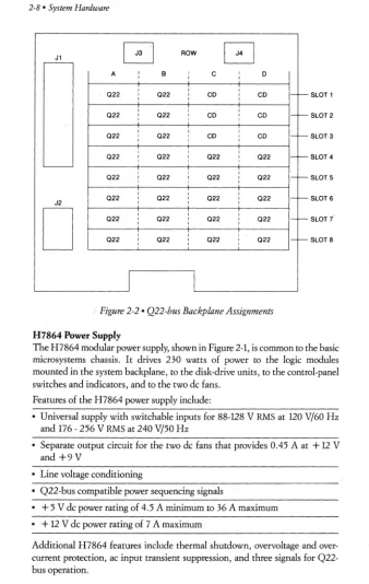
The logic modules for the MicroVAX I, MicroPDP-ll/73, and MicroPDP-ll/23 are installed into the H9278-A backplane assembly. The backplane is included with the system chassis. The assembly consists of four rows by eight slots of prewired connectors and a mounting frame that allows quad- or dual,height logic modules to be easily inserted and removed. A card guide also permits the latches on the quad-height modules to hold securely onto the backplane. The backplane incorporates the Q22-bus wiring in rows A and B of connector slots one through eight and in rows C and D of connector slots four through eight. The Q22 bus supports an interrupt and DMA grant-continuity scheme for the logic modules installed in the backplane. Table 2-1 shows each microsystem's module placement assignments, and Figure 2-2 shows the backplane slot locations listed in Table 2-l.
The backplane provides the 220-ohm far-end termination for the MicroVAX I
and the 120-ohm far-end termination for the MicroPDP-ll systems. Refer to Appendix A-Q-bus for detailed information on 120-ohm and 220-ohm bus termination on the backplane.
Table 2-1 • Logic-module Assignments
Slot Row MicroVAXI MicroPDP-ll/73 MicroPDP-ll/23
ABCD CPU CPU CPU
2 ABCD CPU Memory Memory
3 ABCD Memory Additional mem- Additional
mem-ory or communica- ory or communica-tions option tions option
4 ABeD Additional mem- Two dual-height Two dual-height ory or communica- options or one options or one tionsoption quad-height quad-height
option. option.
RQDXl if it is the RQDXl if it is the las t -used slot. last-used slot. 5 ABCD Two dual-height See Slot 4 See Slot 4
options or one quad-height option.
RQDXl if it is the last-used slot.
6 ABCD See Slot 5 See Slot 4 See Slot 4
7 ABCD See Slot 5 See Slot 4 See Slot 4
2-8 • System Hardware
~
G
ROWG
A I
I B I
I C
I
I D
I , I
I-f--022 I I 022 I , CD I CD
I SLOT 1
I , ,
I f -022 , I 022 I CD I CD
I , SLOT 2
,
I I022 , 022 , CD I CD
I-f--I I I SLOT 3
, I I
I-f--022 I 022 I 022 I 022
I I , SLOT 4
L
-I I I
022 I f
-022 I 022 I 022 I
I I I SLOT 5
, , I
I f
-022 , 022 I 022 , 022
J2 I I I SLOT 6
D
, I ,I-f--022 I , 022 I I 022 I I 022
, , I
022
I-f--022 I 022 , 022 I
I I I
SLOT i
SLOT 8
[image:22.386.17.355.25.558.2]I
l
Figure 2-2 • Q22-bus Backplane Assignments
H7864 Power Supply
The H7864 modular power supply, shown in Figure 2-1, is common to the basic micro systems chassis. It drives 230 watts of power to the logic modules mounted in the system backplane, to the disk-drive units, to the control-panel switches and indicators, and to the two dc fans.
Features of the H7864 power supply include:
• Universal supply with switchable inputs for 88-128 V RMS at 120 V/60 Hz and 176 - 256 V RMS at 240 Vj50 Hz
• Separate output circuit for the two dc fans that provides 0.45 A at + 12 V and +9V
• Line voltage conditioning
• Q22-bus compatible power sequencing signals
• + 5 V dc power rating of 4.5 A minimum to 36 A maximum • + 12 V dc power rating of 7 A maximum
Control Panel
The microsystem control switches and indicator lights are located on the control panel at the front of the microsystem chassis. This control panel is common to each microsystem chassis. Figure 2-3 shows the pushbuttons and indicators for the floor stand unit. These controls allow you to apply and remove the ac power, to stop and start the current program operation, and to protect the data stored on the RD51 or RD52 Winchester disk drive.
• ac Power-is controlled by the ac power rocker switch marked 0 and 1. When power is applied, the pushbutton lights orange.
• Halt Pushbutton-halts the operation of the current program. When the switch is activated, the indicator on the pushbutton lights orange. Restart/ bootstrap operations are inhibited when the Halt pushbutton is depressed. • Restart Pushbutton-used to initiate a processor restart when the Halt
pushbutton is not activated.
• Fixed Disk 0 Write Protect Pushbutton-used to prevent data from being written to the fixed disks. When the switch is activated, the orange indicator in the pushbutton lights.
• Fixed Disk 0 Ready Pushbutton-disables the fixed-disk drives to prevent data from being read from or written to the disk. When activated, the green indicator in the pushbutton lights. The indicator lights intermittently when the disk is reading or writing data during normal operation.
• Run Indicator-when the processor is operating, the run indicator lights green.
• DC OK Indicator-when the de voltages in the system unit are correct, the DC OK indicator lights green.
• Removable Disk Write Protect 1-when data cannot be written to removable disk 1 in the RX50, the indicator lights orange.
2-10· System Hardware
~DmDDmD
I
0
Roc DC OK
•
•
Hall Restart
~
[§]
FlxedOlskO Write Protect Ready
[§TI
~
Removable Disk Write
•
•
Protect,
2Figure 2-3 • Control Panel
I/O Distribution Panel
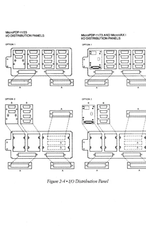
The I/O distribution panel, located at the rear of the microsystem chassis, is used to connect the cables from the console terminal, printing terminal, and other external devices that operate with the system. The I/O distribution panel, shown in Figure 2-4, contains six areas to mount connectors for these devices, and also provides signal filtering and shielding against electromagnetic and mdio frequency interference (EMI/RFI). Each module that sends a cable outside the chassis has a pa:nel insert that mounts in the I/O distribution panel. The external cable attaches to a connector on this panel. Insert panels come in two standard sizes: small (1 X 4 inches) and large (2 X 3 inches). The I/O distribution panel has apertures for four large inserts and two small inserts, or two large inserts and five small inserts (two of the large apertures can be converted to three small apertures).
MicroPDP-11123
1/0 DISTRIBUTION PANELS
OPTION 1
A
/
/ /
I
01
l(:1
A
,
,
1~1
A10
S
I
MicroPDP-11173 AND MicroVAX I 1/0 DISTRIBUTION PANELS
OPTION 1
OPTION 2
[image:25.391.35.328.89.542.2]A
2-12· System Hardware
Fans
Two brushless fans within the microsystem unit provide a flow of air from left to right (side-to-side) to cool the internal assemblies and modules as shown in Figure 2-1. Power for the fans is provided by the H7864 dc power supply.
Enclosures
The microsystems are available in three different system packages as shown in Figure 2-5. All three packages incorporate the same components that are shown in Figure 2-1. Each microsystem has a chassis, CPU, a choice of memory, a choice of integrated fixed-disk and/or dual-diskette drives, one or two serial-line units, and a Q22-bus backplane for additional interfaces and expansion. The floorstand and tabletop units are enclosed
m.
an outer shell and include a front cover and rear I/O distribution panel cover. The floorstand unit includes a base which is attached to the bottom of the microsystem unit.The rackmount unit can be installed into a 19-inch-wide (48.26 centimeters) rack or cabinet and contains a front cover and chassis cover. The mounting hardware for installation into the rack is also included.
FlOORSTAND
RACK-MOUNT
CABINET-MOUNTED
2-14· System Hardware
. Configurations
Each of the microsystems is available in a variety of configurations. The Micro VAX I is available in System Building Block configurations. The MicroPDP-11/73 is available in Base System, Packaged System, and System Building Block methods. The MicroPDP-11/23 is available in Base and Packaged Systems only. The following section briefly describes each of these configuring methods. Detailed configurating information can be found in the PDP-ll Systems and Options Catalog. Copies of this publication can be obtained from your local Digital sales representative or by ordering them direct from Digital. Refer to Appendix E for information on how to order documentation.
Base Systems
The base system is a method of selecting a 11/73 and MicroPDP-11/23 system with a preconfigured CPU, micro system chassis, enclosure, load device, main-storage device, backup-storage device, and memory.
Packaged Systems
The packaged system allows MicroPDP-11/73 and MicroPDP-11/23 customers to choose a pre-configured hardware system and software license. Each packaged system includes a CPU, microsystem chassis, enclosure, communications device, load and backup-storage device, main-storage device, memory, and a PDP-11 operating-system general license. In certain configurations, a U.S.A. country kit may also be included.
System Building Blocks
The system building block is the most popular way to select a hardware and software microsystem configuration. System building blocks are available for the MicroVAX I and the MicroPDP-11/73. Every micro system component is offered as part of a menu. First, a CPU must be chosen with the appropriate amount of memory from the CPU menu, and then each of the remaining components must be chosen from their own specific menu. The menu categories are storage device, load device, enclosure, communications device, console terminal, and software license. System building blocks are flexible because they offer a wide range of components, are customer-tailorable, and also make configuring very easy.
Country Kits
For MicroPDP-11 systems, user documentation comes in a country kit which must be ordered with the system. Also included in the kit are customer-runnable diagnostics. User documentation in English is supplied with the MicroVAXI.
. Additional Documentation
Micro VAX I CPU Technical Description
KDJll-A CPU Module User's Guide
KDFll-B CPU Module User's Guide
PDP-ll Systems and Options Catalog
EK-KD32A-TD
EK-KDJ1A-UG
Once a microsystem is selected, the hardware options that best suit the application must also be chosen. These options include memory, options which enhance the system's performance, storage devices, communications devices, terminals, printers, and modems. Most of these options are compatible with every member of the micro systems family. All of the options required to complete or expand a microsystem are described in this chapter .
. Memory Options
Two types of memory options are available for the microsystems-the MSVll-QA and the MSVll-P series. These memory options can often improve system performance. Each provides the capability to perform direct-memory access. During direct-memory access operations, data is transferred without processor intervention using block-mode transfers. Up to 16 words or 36 bytes of information can be transferred by specifying a starting address.
MSVll-QA
The MSVll-QA memory module is a random-access memory (RAM) module that provides 1 Mbyte of main-memory storage. This memory is implemented on a single, quad-height module using 64-Kbit MOS RAM integrated circuits. MSVll-QA supports 22-bit addressing so that up to 4 Mbytes of physical memory can be configured.
The following are the main features of the MSVll-QA:
• Offers 1 Mbyte of MOS memory on a single, quad-height module • Uses 64-Kbit MOS RAM chips
• Supports 22-bit addressing for up to 4 Mbytes of physical memory • Supports block-mode DMA
• Has LEDs for parity-error checking
MSVll-P Series
3-2 • System Options
The following are the main features of the MSVll-P series:
• Offers 256 or 512 Kbytes of MaS memory on a single, quad-height modul~
• Uses 64-Kbit MaS RAM chips
• Supports IS-bit or 22-bit addressing for up to 4 Mbytes of physical memory • Supports block-mode DMA transfers
• Has LEDs for parity-error checking
. Performance Options
Three options are available to enhance the performance of the MicroPDP-ll/23. A floating-point processor and floating-point accelerator are available for applications that require a great deal of calculation. A character-string instruc-tion set (Commercial Instrucinstruc-tion Set) is also offered for business applicainstruc-tions.
KEFll-AA Floating-point Processor
KEFll-AA is a single- and double-precision floating-point option. This option expands the capability of the MicroPDP-ll/23 by adding the microcode to implement PDP-ll floating-point instructions. The microcode resides in two chips in one 40-pin package that mounts directly on the CPU module.
It
performs operations on 32-bit and 64-bit floating-point numbers and provides up to 17 digits of precision. KEFll-AA also provides integer to floating-point conversions.FPFll Floating-point Accelerator
FPFll is a single-precision and double .. precision fast floating-point hardware option that executes instructions approximately six times faster than the KEFll-AA. This option is a single, quad-height module for the MicroPDP-ll/23 and mounts adjacent to the CPU. FPFll performs hardware operations on 32-bit and 64-32-bit floating-point numbers and provides up to 17 digits of precision. Like the KEFll-AA, it provides integer to floating-point conversions.
KEFll-BB Character-string Instruction Set
. Storage Options
There are many storage options available for the microsystems. These options are offered in several different technologies so that the correct choice can be made for the storage application. Whether storage is being added for media backup, for loading software, for main storage, or for software interchange with another system, Digital has the appropriate storage device for the task.
RQDXl Disk Controller
The RQDXl is a single, quad-height, intelligent controller that provides data transfers between the Q22 bus and the RX50 dual-diskette drive; and one or two RD51 or RD52 fixed-disk drives. The RQDXl logic provides the necessary data buffering and control to allow direct-memory access (DMA) transfers using the Mass Storage Control Protocol (MSCP).
A flat cable attaches to a 50-pin connector mounted at the edge of the module and to the signal distribution board located near the Q22-bus backplane. Signals and data are then transferred from the connectors on the distribution board to the disk-drive assemblies. Four LED indicators are also mounted near· the edge of the module to display octal codes during the self-test program operation.
The following are the main features of the RQDXl:
• Controls up to four logical disk-drive units (two fixed-disk drives and one dual-diskette drive)
• Supports block-mode DMA data transfers • Has maintenance self-test programs • Uses LEDs for parity-error checking
RLVU Disk Controller
The RLV12 controller is a single, quad-height module for the MicroPDP-ll family that interfaces the RL02 removable-disk drives to the Q22 bus. One RLV12 controls up to four RL02 disk drives. The RLV12 transfers data to and from the Q22 bus using direct-memory access transactions. It performs a cyclic redundancy check on· data and headers. Memory is parity-checked, and the current command to the RLV12 is aborted when the error is detected. The following are the main features of the RLV12:
3-4 • System Options
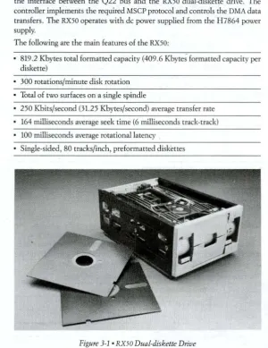
RX50 Flexible
Disk
Programs and data can be entered into and removed from the microsystems through the RX50 dual-diskette drives (shown in Figure 2-1 and in Figure 3-1). The RX50 is a single unit that contains two separate diskette drives. Each of the two drives in the RX50 operate with a 5.25-inch flexible diskette and provide a storage total on both diskettes of up to 819.2 Kbytes of formatted data. Access to the drive is through' the two doors located at the front of the drive unit.
The RQDXl controller module, located in the Q22-bus backplane, provides the interface between the Q22 bus and the RX50 dual-diskette drive. The controller implements the required MSCP protocol and controls the DMA data transfers. The RX50 operates with dc power supplied from the H7864 power supply.
The following are the main features of the RX50:
• 819.2 Kbytes total formatted capacity (409.6 Kbyte; formatted capacity per diskette)
• 300 rotations/minute disk rotation
• Total of two surfaces on a single spindle
• 250 Kbits/second (31.25 Kbytes/second) average transfer rate
• 164 milliseconds average seek time (6 milliseconds track-track)
• 100 milliseconds average rotational latency
[image:34.366.33.334.148.538.2]• Single-sided, 80 tracks/inch, preformatted diskettes
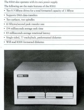
RX02 Flexible Disk
The RX02, shown in Figure 3-2, is a double-density, flexible-diskette drive that
operates with 8-inch diskettes. Direct-memory access is used to provide rapid
data transfer and efficient utilization of the host processor. The RX02 includes
two O.5-Mbyte drives, for a total of 1 Mbyte, and a controller with interco n-necting cables. The dual dfives are packaged as a rackmount or tabletop unit.
The RX02 also operates with its own power supply. The following are the main features of the RX02:
• Two O.5-Mbyte drives for a total formatted capacity of 1 Mbyte
Supports DMA data transfers
• Two surfaces, two spindles
• 61 Kbytes/second peak transfer rate • 154 milliseconds average seek time
83 milliseconds average rotational latency
• Single-sided, 77 tracks/inch, preformatted diskettes
[image:35.374.22.310.131.505.2]• Will read RXOl formatted diskettes
3-6 • System Options
RD51 and RD52 Fixed Disks
The RD51 and RD52 fixed-disk drives are compact, Winchester disk drives (shown in Figure 2-1 and in Figure 3-3), that provide reliable mass-data storage for the microsystems. The drives contain double-sided, 5.25-inch, nonremov-able disks enclosed in a sealed assembly. A microprocessor within the unit controls the data transfers. The RD51 disk drive can store up to 11 Mbytes of formatted data, and the RD52 disk drive can store up to 31 Mbytes of formatted data.
The RQDXl controller module, located in the Q22-bus backplane, is the interface between the Q22 bus and the disk-drive units. The controller module establishes the required MSCP protocol to allow direct-memory access between the CPU, memory, and the disk-drive units. Both the RD51 and RD52 units operate from the dc power of the H7864 power supply.
The following are the main features of the RD51: • 11 Mbytes formatted capacity
• Supports DMA data transfers • Four surfaces on a single spindle
• 5 Mbits/second (625 Kbytes/second) peak transfer rate • 93.3 milliseconds average access time
• 8.33 milliseconds average rotationallatency The following are the maillfeatures of the RD52: • 31 Mbytes formatted capacity
• Supports DMA data transfers • Eight surfaces on a single spindle
• 5 Mbits/second (625 Kbytes/second) peak transfer rate • 57.5 milliseconds average access time
3-8 • System Options
RL02 Removable Disk
The RL02, shown in Figure 3-4, is a lO.4-Mbyte, removable-cartridge disk drive for the MicroPDP-ll family. Direct-memory access is used to provide rapid data transfer and efficient utilization of the host processor. The RLV 12
controller module, located in the Q22-bus backplane, is the interface between
the Q22 bus and the removable-disk unit. The controller module establishes the required protocol to allow direct-memory access between the CPU, mem-ory, and drive unit. The RL02 operates with its own power supply.
The following are the main features of the RL02:
• 10.4 Mbytes formatted capacity
Supports DMA data transfers
• Two surfaces on a single spindle
• 512 Kbytes/second peak transfer rate
• 67.5 milliseconds average access time
12.5 milliseconds average rotational latency
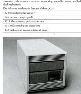
RQC25 Fixed/Removable Disk
The RQC25, shown in Figure 3-5, is a 26-Mbyte, Winchester fixed-disk unit combined with a 26-Mbyte, sealed removable-cartridge disk unit for a total of 52 Mbytes. The RQC25 contains its own intelligent controller (KLESI) and onboard microdiagnostics for maintenance. The removable-cartridge portion of the disk provides a one-to-one backup ratio, and is a low-cost alternative to traditional disk/tape configurations. The RC25 is also a 52-Mbyte, Winchester, fixed/removable disk drive but without a controller. It can be added onto the
RQC25 to give the microsystem a total of 104 Mbytes of storage.
Because it uses the Mass Storage Control Protocol, the RQC25 is compatible with other Digital Storage Architecture disk subsystems. Exceptional data reliability and integrity features include a powerful 170-bit error detection and correction code, automatic retry and revectoring, embedded servos, and bad-block replacement.
The following are the main features of the RQC25:
• 52 Mbytes formatted capacity
Four surfaces, single spindle
• 1025 Kbytes/second peak transfer rate
• 45.5 milliseconds peak access time
[image:39.367.33.319.191.521.2]• 10.5 milliseconds average rotational latency
3-10 • System Options
TQK25 Cartridge Tape
The TQK25, shown in Figure 3-6, is a cartridge-tape drive packaged in a standalone tabletop enclosure for the MicroPDP-ll family.
It
is designed for fast backup of the RD51 and RD52 fixed disks. The TQK25 will serially record up to 60 Mbytes on a DC600A 0.25-inch tape that is enclosed in a sealed cartridge.It
can copy any of today's mini-Winchester disks onto a single cartridge. The TQK25 cartridge-tape drive also comes with its own universal power supply with cooling, a quad-slot Q22-bus controller module (TSll emulation), a 16- or 32-inch (41- or 81-centimeter) internal CPU cable, and a 9-foot (2. 74-meter) CPU-to-drive cable.The following are the main features of the TQK25: • 60 Mbytes formatted capacity
3-12· System Options
TU58 Cartridge Tape
The TU58, shown in Figure 3-7, is a dual cartridge-tape drive offering 256 Kbytes of formatted data storage per drive. It is a random-access device that reads and writes on block-addressable, preformatted cartridge tapes. The TU58 consists of a controller, two drives, universal power cords, boot chip, 1 8-foot (5.5-meter) cable to interface with a serial-line unit (DLVE1 or DLV]l, which is a prerequisite), and two cartridge tapes.
The following are the main features of the TU58:
• 256 Kbytes formatted capacity per cartridge
• 800 bits/inch recording density
3.7 Kbytes/second peak transfer rate
[image:42.364.46.322.67.469.2]• 30 inches/second read/write speed
TSV05 Streaming Tape
The TSV05, shown in Figure 3-8, is a magnetic-tape drive for the MicroPDP-ll family that includes a tape transport with an integral formatter and a single,
quad-height controller module. It features a storage capacity of 40 Mbytes using 8-Kbyte blocks, 25/100 inches/second streaming-tape backup, and front-loading automatic tape threading. The TSV05 supports industry-standard 1600 bits/inch phase-encoded format and ANSI compatibility. The tape transport
occupies only 8.7 inches (22 centimeters) in a H9642-type 41.7 -inch-high (106-centimeter) cabinet, allowing ample room for expansion. The TSV05 is also available without the cabinet for system integrators.
The following are the main features of the TSV05:
• 40 Mbytes formatted capacity (2400-foot reel)
• Front loading
• 1600 bits/inch recording density Automatic tape threading
• 40 or 160 Kbytes/second peak transfer rate
• 8.7 inches high
25/100 inches/second read/write speed (preset by user)
3-14· System Options
· Communications Options
The communications capability of the each of the microsystems can be expanded by communications interface options. These options enable asyn-chronous, synasyn-chronous, and realtime data transfers between two or more systems, and also between a host system and its user terminals, modems, and other external devices. Each option consists of an interface module, internal cables, and a panel insert. The interface module installs into a slot in the Q22-bus backplane, and the device connector panel insert is mounted in the I/O distribution panel at the rear of the microsystem chassis. Refer to the PDP-ll Microcomputer Interfaces Handbook for detailed information on the following communications options. Appendix E has the ordering information for this handbook.
Asynchronous Interfaces • DZVll
The DZVll is a four-line, asynchronous multiplexer that provides local or remote interconnection between the microsystems and EIA RS232-C/CCITT V.28 terminals or other systems. The DZVll operates at program-selectable speeds up to 9600 bits/second at full-duplex with limited-modem control on each line.
The DZVll is a single, quad-height module. It is compatible with Digital's family of modems and with the Bell 100 and 200 series of modems and their equivalents. The DZVll does not support half-duplex operations on modems.
• DHVll
The DHVll is an eight-line, asynchronous, direct-memory access multiplexer that provides local or remote interconnection between the microsystems and EIA RS232-C/CCITT V28 terminals or other systems. Direct-memory access reduces system overhead for terminal-intensive applications. The DHVll operates at program- or jumper-selectable speeds up to 38,400 bits/second at full-duplex with full-modem control on each line. Split-speed transmit and receive rates are supported on each line making more efficient use of communi-cations facilities by reducing the software demand.for the receive line. The DHVll is a single, quad-height module. It is compatible with Digital's
~~cl~~~~~M~~~~cl~~~~
• DZQll
The DZQll is a four-line, asynchronous multiplexer that provides local or remote interconnection between the microsystems and EIA RS232-C/CCITT V.10 terminals or other systems. The DZQll operates at program-selectable speeds up to 9600 bits/second at full-duplex with limited-modem control on each line.
The DZQll is a single, dual-height module. It is compatible with Digital's family of modems and with the Bell 100 and 200 series of modems and their equivalents.
• DLVJl
The DLVJl is a four-line, asynchronous interface that provides local or remote interconnection between the MicroPDP-ll systems and ErA RS232-C/CCITT V.8, EIA RS422/CCITTV.ll, and EIA RS423/CCITTV.10 terminals. The DLVJl acts as four separate devices, making program operations more convenient than they are with a multiplexer. The DLVJl operates at program- or jumper-selectable speeds from 150 to 38,400 bits/second at full-duplex. Limited-modem control is included. Split-speed transmit and receive rates are supported on each line making more efficient use of communications facilities by reducing the software demand for the receive line.
The DLVJl is a single, dual-height module. It is compatible with Digital's family of modems and with the Bell 100 and 200 series of modems and their equivalents.
Diagnostic support is available for the DLVJl on the MicroVAX I, which is supported only as an OEM add-on device.
• DLVE1
The DLVEl is a single-line, asynchronous interface that provides local or remote interconnection between the MicroPDP-ll systems and EIA RS232-C/ CCITT V.28 terminals. The DLVEl operates at program- or jumper-selectable speeds from 50 to 19,200 bits/second at full-duplex. Limited-modem control is included. Split-speed transmit and receive rates are supported making more efficient use of communications facilities by reducing the software demand for the receive line.
3-16 • System Options
Synchronous Interfaces • DEQNA
The DEQNA is a high-performance, synchronous, communications controller that connects the microsystems to an Ethernet Local Area Network (LAN). The DEQNA complies fully with the Ethernet specification and operates at 10 Mbits/second.
The DEQNA provides Ethernet data-link layer functions and a portion of the physical channel functions. The DEQNA is supported under DECnet Phase IV software. Digital also provides documentation and device drivers so that users can write their own higher-level protocols for specialized applications and communications in multivendor environments. The DEQNA allows communi-cations with up to 1023 addressable devices on an Ethernet. It physically and electrically connects to the Ethernet coaxial cable via Ethernet transceiver cables and an H4000 Ethernet transceiver, or a Lecal Area Interconnect (DELNI). The Physical Address ROM (DEXMR) is required to downline load software to a diskless Ethernet node with a DEQNA.
The DEQNA is a single, dual-height module .
• DMVll
The DMVll is a microprocessor-controlled, single-line, synchronous interface that provides local or remote interconnection between the microsystems and other computer systems with EIA RS232-C/CCITT V.28, or RS423/RS449 interfaces. The DMVll implements DDCMP in hardware and supports direct-memory access data transfers, DECnet point-to-point or multipoint configura-tions, and full-modem control. It operates at speeds from 19,200 bits/second to 56,200 bits/second (depending on the version selected) at haIf- or full-duplex. Depending on the operating system and layered software, the DMVll can support up to 12 tributaries. In multipoint configurations, these tributaries can be other DMVlls or DMPlls. In point-to-point configurations, the DMVll can communicate with other DMVlls, DUPlls, DMRlls, or DMPlls.
• DPVll
The DPVll is a single-line, synchronous, programmable interface that provides local or remote interconnection between the microsystems and other computer systems with EIA RS232-C/CCITT V.28 or EIA RS232-C/CCITT V.ll interfaces. It operates at speeds up to 56,000 bits/second at half- or full-duplex with fuII-modem control. The DPVll is programmable for either byte-oriented protocols (DDCMP or BISYNC) or bit-oriented protocols (SDLC or HDLC). The DPVll is suited for interfacing to medium-speed synchronous lines for remote batch and remote job-entry applications.
The DPVll is a single, dual-height module. It is compatible with Digital's family of modems and with the Bell 200 series of modems and their equivalents.
·KMVll
The KMVll is a high-performance, direct-memory access, single-line, program-mable, communications controller that provides local or remote interconnec-tion between MicroPDP-ll systems and other computer systems with EIA RS232-C/CCITT V.28, EIA RS422/CCITT V.l, or EIA RS423/CCITT V.10 inter-faces. It is capable of communications speeds up to 64,000 bits/second. The KMVll utilizes the MICRO/Tll processor to perform user-defined communica-tions funccommunica-tions, thereby freeing the host to do more application computacommunica-tions. The KMVll can be programmed in synchronous or asynchronous modes. It is implemented as a single, quad-height module. The KMVll also provides fuIl-modem support for Digital's family of fuIl-modems, the BeIl200 series of fuIl-modems or their equivalents, and European-PPT approved modems.
Realtime Interfaces • DRVll-WA
The DRVll-WA is a general-purpose, direct-memory access, parallel-line, inter-face unit with 22-bit addressing capability. It permits block-mode DMA data transfers at rates up to 250 Kwords/second in single-cycle mode, and up to 500 Kwords/second in burst mode. The DRVll-WA is a single, dual-height module .
• DRVll-]
3-18 • System Options
• AAVll
The AAVll is a four-channel, digital-to-analog converter module for the MicroPDP-ll family that includes control and interfacing circuits. It has four DI A converters, a dc-to-dc converter that provides power to the analog circuits, and a precision voltage reference. Each channel has its own holding register that can be addressed separately and provides 12 bits of resolution. The AAVlI is a single, dual-height module and is available as an add-on option only.
• ADVll
The ADVll is a 12-bit, successive approximation, analog-to-digital converter module for the MicroPDP-ll family that samples analog data at specified rates and stores the digital equivalent value for processing. A multiplexer section can accommodate up to 16 single-ended or 8 quasi-differential inputs. The converter section uses a patented auto-zeroing design that measures the sample data with respect to its own circuitry offset and, therefore, cancels out its own offset error. The ADVll is a single, dual-height module and is available as an add-on option only .
• AXVll
The AXVll is an analog input/output module for the MicroPDP-ll family that accepts up to 16 single-ended inputs or up to eight differential inputs, either unipolar or bipolar. The AXVll also has two separate digital-to-analog (DIAl converters. Each D/A converter has a write-only register that provides 12-bit input data resolution. On receiving the data, the AXVll changes it to an analog output voltage. The AXVll is a single, dual-height module and is available as an add-on option only.
• KWVll
Terminals, Printers, and Modems
Digital offers a complete line of video terminals, printers, and modems for the microsystems. A terminal or device can be selected that incorporates the features that the application requires. A detailed description of all the video terminals and can be found in the Tenninals & Printers Handbook. Refer to Appendix E for ordering information for the handbook.
Video Terminals
Video-display terminals use a cathode-ray tube (CRT) screen for output and a typewriterlike keyboard for input. Alphanumeric-video terminals are capable of displaying letters, numbers, and special characters in a fixed format. Graphics-video terminals can individually manipulate picture elements on the display screen and can represent graphs, charts, and pictures. Typically, a graphics terminal can also emulate an alphanumeric terminal. Table 3-1 is a comparison chart of the alphanumeric and graphics video terminals.
Thble 3-1· Video-terminal Features
Universal
Asychro-VT100 Advanced nous
Family Video Printer Local Communi- Integral Model Features Keyboard Features Graphics Port Echo cations Modem
VTlO1 X ANSI X X Full Duplex OPT Numeric
VT102 X ANSI X X X Half/full OPT
Numeric Duplex
Word Processing
VTl25 X ANSI X X X Full Duplex OPT Numeric
Word Processing
VT220 X ANSI X X X Full Duplex Numeric
VT240 X ANSI X X X X Full Duplex Numeric
3-20 • System Options
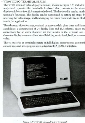
• VT100 VIDEO- TERMINAL SERIES
The VT100 series of video-display terminals, shown in Figure 3-9, includes a sculptured typewriterlike detachable keyboard that connects to the
video-display unit by a 6-foot (1.9-meter) coiled cord. The keyboard is used to set the
terminal's functions. The display can be customized by setting tab stops, by reversing the video image, and by changing the cursor from underline to block
to suit the application.
The advanced video features, optional on some models, gives three additional capabilities: a combination of 24 display lines and 132 columns, space and connections for an extra character set that resides in the terminal, and a
character display in any combination of blinking, underlined, bold, or reversed video.
[image:50.368.34.322.53.467.2]The VT100 series of terminals operate on full-duplex, asynchronous communi-cations lines and are equipped with a standard ErA RS232-C interface.
• VTlO1
The VTlOl, a low-cost video terminal, provides 24 lines of 80 characters or 14 lines of 132 characters. Characters can be underlined or represented in reverse video. The display includes smooth scrolling and split-screen operation. The operator can set the terminal characteristics from the keyboard.
Communications with the system are full-duplex and asynchronous.
• VTl02
The VTl02 terminal functions like a VT100 terminal with the advanced video and printer port options. The monitor displays 24 lines of 80 or 132 characters with individually selectable attributes including bold, blink, underline, or reverse video. Double-width, double-height characters can be used for legibil-ity at a distance. Text can scroll smoothly up the screen rather than jump a full line at a time. The screen can be split into scrolling and nonscrolling regions. Many of the terminal's operating characteristics can be changed from the keyboard.
Asynchronous communication with the system can be full-duplex, full-duplex with asymmetric speeds, or half-duplex with modem control. Automatic synchronization codes (XOFF tells the computer to stop sending data, X()N to start again) allow fast data transfers without the loss of information. The VT102 can connect to a dedicated printer, such as an LA 100 or LA50, to produce a hardcopy printout of the video screen.
The VTl02 video terminal is also available in a rugged version for use in harsh environments. The RT102 has a sheet-steel case, a heavy-duty filtration system, and a sealed keyboard.
• VTl25
The basic VT125 combines bit-mapped, monochrome graphics and a printer port with VT100 functionality. The advanced video option increases the number of 132-character lines to 24 and allows selection of any combination of bold, blink, underline, and reverse video attributes on a character-by-character basis.
3-22 • System Options
planes provide" four monochrome intensities on the VT125 terminal screen-black, white, and two shades of gray. When attached to an external color monitor, the VT125 can generate four colors from a palette of 64 using both graphics planes. The VT125 can be connected directly to a graphics printer such as the LA 100 or LA50 for a hardcopy printout of the screen .
• VT200 VIDEO- TERMINAL SERIES
The VT200 series is Digital's newest offering of video terminals. The VT200
terminals include all of the universal features of the VT100 series of video terminals. The VT200 units are smaller in size than the VT100 units and include low-profile packaging. A series of setup menus make tailoring the terminal to the application very easy .
• VT220
The VT220, a monochromatic, text-only terminal, shown in Figure 3-10,
incorporates full VT100 functionality. The terminal features include a 12-inch nonglare screen, low-profile packaging, and an adjustable monitor. The VT220
terminal includes VT52 terminal emulation, advanced-video features, built-in printer port, and U.S.A./European modem controls. The international capa-bilities include a multinational character set, universal power supply, and both 20 milliampere and ErA interfaces. A plain-language set-up menu, programma-ble function keys, and selective-erase feature combine to make the VT220
[image:52.366.40.323.321.540.2]terminal easy to use. Operator-oriented features such as split screen, bidirec-tional smooth scrolling, double-height and double-width characters, and reverse video allow the VT220 terminal to be used for many applications.
• VT240 AND VT241
The VT240 is a monochromatic, text and graphics video-display terminal. It
incorporates all the features of the VT100 family and the VT220 terminal, is completely self-contained, and requires no upgrading.
The VT240 terminal supports the industry's graphics standards by generating full bit-mapped graphics in both ReGIS and Tektronics 4010/4014 emulation. ReGIS is Digital's general-purpose graphics descriptor. It allows pictorial data to be created and stored very easily. By connecting this terminal to a graphics printer, such as the LAlOO, the contents of the display can be reproduced. The VT240 terminal consists of the same keyboard that is used for the VT220
terminal, a monitor, and a system box. The system box contains the power
supply, control-circuit board, and electrical connectors.
The VT241 terminal offers all the capabilities of the VT240 terminal and
[image:53.364.41.320.230.528.2]includes a color monitor for four-color text and graphics output. Both the VT240 and the VT241 are shown in Figure 3-11.
3-24 • System Options
Printing Terminals
Several printing terminals are available for operation with the microsystems. These terminals include large, free-standing units and small, desktop units. Table 3-2 provides a comparison of the features available with the printing terminals.
Table 3-2 • Printing-terminal Features
Print Speed Parts
Model and Quality Graphics per Form Paper Feed Special Features
LA50 100 chis draft X 3 Friction DEC PC-compatible
50 ch/s memo Low tear-off
tractor
LA 100 240 chis draft X 4 Friction DEC PC-compatible
30 chi s letter Tractor Plug-in fonts
Sheet OPT
80 ch/s memo OPT Roll OPT
LAl20 180 chis draft 9 Tractor High-volume printing
LA210 240 chis draft X 4 Tractor IBM PC-compatible 40 chis letter Sheet OPT DEC PC-compatible
10 languages 80ch/s memo OPT
LA12 150 chis draft X 2 Friction Dial through the
80ch/s memo Pin keyboard modem
Roll and/or acoustic Tractor OPT coupler LQP02 32 chi s letter OPT 4 Friction WPS-compatible
Sheet OPT Full-character Tractor OPT printing LQP03 27 chi s letter OPT 4 Friction PC-compatible
Sheet OPT Full-character Tractor OPT printing LN03 8 pages/min Cutsheet High-resolution
• LA50 PERSONAL PRINTER
The LA50, shown in Figure 3-12, is a low-cost, tabletop printer. Its impact
dot-matrix mechanism prints 7 X 9 matrix characters at 100 characters/second in draft mode, 13 X 9 characters at 50 characters/second in memo mode, as well as bit-map graphics.
Characters can be printed at pica (10) or elite (12) pitch, as well as compressed
(16.5) for 132 characters on a line. Each pitch can also be printed in double-width characters. The LA50 has 250 printable characters, including:
• The standard 96-character ASCII set • VT100 terminal special-character set
• 8-bit multinational-character set
[image:55.368.34.319.115.469.2]• 11 national-character sets
3-26 • System Options
• LA100 (LETTERPRINTER 100 AND LETTERWRITER 100)
The LAIOO printing terminals, shown in Figure 3-13, provide flexibility in a
tabletop unit about the size of an electric typewriter. The Letterwriter 100 is a keyboard send/receive (KSR) terminal, and the Letterprinter 100 is receive-only
(RO). Both can print on friction-fed paper or with an optional tractor-fed paper. The impact dot-matrix printer offers you a choice of print quality and speed.
In draft mode, it prints 240 characters/second maximum with a 7 X 9 print matrix. At the other extreme, letter-quality mode gives you a 33 X 18 print
matrix at 30 characters/second. In between these modes is the optional memo-quality mode with its 33 X 9 print matrix and 80 characters/second speed.
Standard fonts included with the LAlOO are Courier-lO and Orator-lO. Optional fonts include Gothic-lO, Symbol-lO, Courier-12, and many others.
[image:56.366.35.322.97.457.2]Fonts can be selected by the system or from the keyboard.
• LA120 DECWRITER III PRINTER
The LA120 freestanding printing terminal, shown in Figure 3-14, is a sturdy, high-performance device with a reputation for reliability. It prints on multiple-copy, tractor-fed paper from 3 inches to 14.8 inches wide, at a maximum speed of 180 characters/second-fast enough to print a typical one-page memo in 20 seconds. Because of its lOOO-character buffer, bidirectional printing, and ability to skip quickly across spaces, the LA120 printer maximizes the printing throughpur.
[image:57.364.30.315.54.518.2]The standard LAl20 printer character set is U.S.A.fUnited Kingdom. Charac-ter sets for Europe or the APL programming language are optional. CharacCharac-ters can be printed in eight sizes and in six choices of vertical-line spacing. Characters are formed by an impact dot-matrix print head in a 7 X 7 dot format. Both keyboard send/receive (KSR) and receive-only (RO) versions are available.
3-28· System Options
• LA210 LETTERPRINTER
The LA210 Letterprinter, shown in Figure 3-15, is a microprocessor-driven, medium-speed, wide-carriage, receive-only (RO), multimode printer that offers similar functionality to the LAIOO personal-computer model plus the addition of IBM personal computer compatibility. The LA210 uses conventional impact dot-matrix printing technology. Dot formations may be of either letter quality (lower speed/higher density), draft quality (higher speed/lower density) and a binary-print mode that allows the host computer to define all dots printed (graphics mode). The three basic modes of printer operation cover a wide range of applications. The LA210 has been designed with the following standard capabilities:
• 240 characters/second draft printing speed • 40 character/second letter-quality printing speed
• Compatibility with Digital and most IBM bit-map graphics printing applica-tions
• Compatibility with the IBM personal computer, IBM-XT, and IBM-AT personal computers and with many IBM personal-computer emulators • Equipped with Courier-lO font with over 30 optional font cartridges
available
• Prints in ten languages plus VT100 line-drawing characters • Wide carriage prints up to 217 characters on 15-inch paper • Styled for office environment
• Forms-handling tractor with acoustic shield • 2000-character input buffer
• Equipped with EIA RS232-C interface