ISSN: 1992-8645 www.jatit.org E-ISSN: 1817-3195
STBC-OFDM SYSTEM BASED ON DISCRETE FRAMELET
TRANSFORM
1
SUHA Q. HADI, 2P. EHKAN, 3M. S. ANUAR, 4AWATIF ALI JAFAAR 1,2,3
School of Computer and Communication Engineering, University Malaysia Perlis, 02060 Arau, Perlis, Malaysia.
4
Electrical Engineering Department College of Engineering Al-Mustansiriya University, Baghdad, Iraq E-mail: [email protected], [email protected], [email protected],
4
ABSTRACT
This paper proposed anew Space Time Block Coded Orthogonal Frequency-Division Multiplexing (STBC-OFDM) system based on Discrete Framelet transform (FT) instead of Fast Fourier Transform (FFT) under different channel environments. The proposed system (STBC-FT-OFDM) has been compared with traditional FFT-OFDM) system and OFDM) based on Discrete Wavelet Transform (STBC-DWT-OFDM) system. Through calculating the Bit Error Rate (BER) performance, it proved that the performance of the proposed system is outperform compared with the performance of the other two systems. BER performance of the system is analyzed by employing various digital modulations technique (BPSK, QPSK) over an Additive White Gaussian Noise (AWGN), flat fading, and multipath selective fading channels
Keywords:OFDM, STBC, Framelet Transform, Wireless Channel, PSK Modulation.
1. INTRODUCTION
Multiple Input Multiple Output (MIMO) system with OFDM, MIMO-OFDM, which has already been adopted for present and future broadband communication standards such as LTE or WiMax. One popular combination of MIMO and OFDM is the combine the STBC with the OFDM system, in STBC-OFDM the data is coded through space and time to improve the reliability of the transmission [1]. The STBC-OFDM technique has been recently considered in the current wireless communication systems, such as IEEE 802.11 a/g, Digital Video Broadcasting for Handheld (DVB-H), and IEEE 802.16 Wireless MAN, due to their high bandwidth efficiency, their robustness to frequency-selective fading, their flexibility in handling multiple data, a simple linear decoding, and low complexity receiver rates [1, 2, 3]. STBC scheme has been proposed by Alamouti in 1998 [3] as a simple two-branch transmit diversity scheme using two transmit antennas and one receive antenna. The author found that the proposed scheme does not require any bandwidth expansion ,any feedback from the receiver to the transmitter, and its computation complexity and the diversity order are similar to as maximal-ratio receiver combining (MRRC) with
one transmit antenna, and two receive antennas . Substantially, Alamouti’s coding is an orthogonal ST block code where two successive symbols are encoded in an orthogonal 2x2 matrix [4].
In [5] it was found that the performance of STBC-OFDM system in frequency selective fading channel under different channel conditions was better than OFDM system without STBC. This Study has shown that the system combined STBC with OFDM could effectively improve the system capacity and confront multipath interference. The effect of modulation order, antenna selection techniques, slow and fast fading conditions and power conditions on the performance of STBC-OFDM had been studied in [1]. From The simulation results, it is found that the BER performance of the system decreases on increase in modulation order. Performance of STBC-OFDM get improves with unequal power conditions and with antenna selection technique. The system performs well in slow fading. If fading is somewhat rapid, it does not achieve good performance.
ISSN: 1992-8645 www.jatit.org E-ISSN: 1817-3195 Discrete Wavelet Transform (DWT) can be a good
solution for these problems, so that there is no need for cyclic prefix. The DWT has the advantages of more flexibility, the higher suppression of side lobes compared to the side lobes of the rectangular window in the Fourier transform, and localized in time and frequency [6].
In [7] the authors proposed MIMO-OFDM based on DWT system, and compared the performance of this system with the performance of MIMO-OFDM based on FFT by applying Alamouti’s algorithm over AWGN and Rayleigh fading channels .They found that DWT based OFDM system performs better than FFT based OFDM without putting any restriction on the number of antennas which are using at the base station as well as at the receiver. Also in [8] the author found that there is an improvement in the BER performance of the wireless system such as MIMO-OFDM, when wavelet transform was used instead of FFT. All the simulation results that were studied by [9] showed that the performance of the discrete Wavelet transform based MIMO multicarrier modulation (MIMO-MCM), are superior to the performance of conventional OFDM in terms of BER and transmission capacity.
Though standard DWT can be obtained as a powerful tool for analysis and processing of many real-world signals and images, it suffers from three major disadvantages, Shift- sensitivity, Poor directionality and Lack of phase information. Frames, or over-complete expansions, have a variety of attractive features. With frames, better time frequency localization can be achieved than is possible with wavelet. Some wavelet frames can be shift invariant, while wavelet bases cannot be. Frames provide more degrees of freedom to carry out design. Framelets shows promise in removing some of the limitations of wavelets. Several applications have benefited from the use of frames, for example, de-noising and signal coding [10, 11].
In this paper, a new construction for the STBC-OFDM system is proposed to achieve better BER performance than the other systems. Inverse discrete Framelet Transform (IFT) will be used in STBC-OFDM transmitter side as a transformation tools instead of IFFT or IDWT, while the discrete Framelet Transform (FT) will be used in the receiver side instead of FFT or DWT.
The paper is organized as follows: section 2 describes STBC based on Alamouti’s algorithm. Section 3, give an introduction to FT. A description for the proposed STBC-FT-OFDM system is
presented in section 4. Results from a simulation performance evaluation are presented in section 5 and finally conclusions are given in section 6.
2. STBC USING ALAMOUTI ALGORITHM
STBC combined orthogonal encode technology, transmission diversity, and realized spatial diversity and time diversity by utilizing union code in time and space, thus improved the performance of the wireless communication system [12]. In STBC scheme of Alamouti, two transmitters (Tx1, Tx2) send the information symbol at the same time, its space-time encoding can be described as follow [3,12,13]:
1 2
2 1
s s
s s
∗ ∗
−
(1)
where s1 and s2 are complex signals to be transmitted and * denotes a conjugate operation. Rows indicate the time domain and columns represent the space domain. The received signal at time t and t +T can be written as:
1 2
1 1 1
* *
2 2 1 2 2
s s
y h n
y
y s s h n
= = +
−
(2)
where h1 and h2 are complex channel responses for antennas 1 and 2, respectively, and n1 and n2
complex noises at times t and t +T.
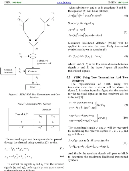
2.1 STBC Using Two Transmitters And One Receiver
ISSN: 1992-8645 www.jatit.org E-ISSN: 1817-3195
Figure 1: STBC With Two Transmitters And One Receiver
Table1:Alamouti STBC Scheme
The received signal can be expressed after passed through the channel using equation (2), so that
1 1 1 2 2 1
y =h s +h s +n (3)
2 1 2 2 1 2
y = −h s∗+h s∗+n (4)
To extract the signals s1 and s2 from the received signals (y1 and y2), both signals y1 and y2 are passed to the combiner as follows:
1 1 1 2 2
s% =h y∗ +h y∗ (5)
After substitute y1 and y2 as in equations (3 and 4) the equation (5) will be as follows:
2 2
( )
1 1 2 1 1 1 2 2
s%= h +h s +h n∗ +h n∗ (6)
Similarly, for signal s2
2 2 1 1 2
2 2
( )
2 1 2 2 2 1 1 2
s h y h y
s h h s h n h n
∗ ∗
= −
∗ ∗
= + + −
%
%
(7)
Maximum likelihood detector (MLD) will be applied to determine the most likely transmitted symbols as shown in equation (8).
( , ) ( , ),...
dist s s% i ≤dist s s% j ∀ ≠i j (8)
where: dist (A, B) is the Euclidean distance between signals A and B, the index j spans all possible transmitted signals.
2.2 STBC Using Two Transmitters And Two Receivers
[image:3.612.75.526.73.670.2]The representation of STBC using two transmitters and two receivers will be shown in figure 2. It’s clear from this figure that the notation for the received signal at the two receivers will be as follow [3]:
11 11 1 12 2 11
1 12 11 2 12 1 12
y h s h s n
For Rx
y h s h s n
= + +
∗ ∗
=− + + (9)
21 21 1 22 2 21
2 22 21 2 22 1 22
y h s h s n
For Rx
y h s h s n
= + +
∗ ∗
=− + + (10)
The transmitted signals s1 and s2 will be recovered by combining the received signals y11,y12, y21, and y22 as follows:
1 11 11 12 12 21 21 22 22
2 12 11 11 12 22 21 21 22
s h y h y h y h y
s h y h y h y h y
∗ ∗ ∗ ∗
= + + +
∗ ∗ ∗ ∗
= − + −
%
%
(11)
And finally the resultant signals will pass to MLD to determine the maximum likelihood transmitted symbols.
Time slot, T
Antenna
Tx1 Tx2
t s1 s2
t+T -s2* s1*
Tx2
Tx1
Channel Estimator
MLD Combiner n1
n2
1
2 s
s %
%
y1 at time =t
y2 at time = t+T
h1
h2
1
*
-2 s
s
2
1 s
s∗
ISSN: 1992-8645 www.jatit.org E-ISSN: 1817-3195
3. DISCRETE FRAMELET TRANSFORM
Framelets are very hassling to wavelets but have some significant differences. Particularly, where there are one scaling functionφ( )t and one wavelet functionψ( )t in wavelets, there are one scaling functionφ( )t and two wavelet functions
( ) 1t
ψ andψ2( )t in framelets. The one scaling function φ( )t and the two wavelet functions
( ) 1t
ψ and ψ2( )t are defined through the low-pass (scaling) filter h0(n) and the two high-pass (wavelet) filters h1(n) and h2(n), as given in the following equations [10, 14].
( )t 2 h0( ) (2n t n) n
φ = ∑ φ − (12)
( )t 2 hi( ) (2n t n), i 1,2. n
ψ = ∑ φ − = (13)
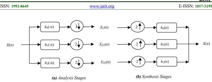
1D- Framelet transform is implemented on discrete-time signals after an appropriate analysis
and synthesis filter bank structure is selected. The analysis filter bank consists of three analysis filters:one low pass filter denoted by h0(-n) and two distinct high pass filters denoted by h1(-n) and h 2(-n), as shown in Figure (3a) . As the input signal travels through the system, the analysis filter bank decomposes it into three sub-bands which generate the low frequency (or coarse) sub-band represented by XL(n) ,and the two high frequency (or detail) sub
bands represented by XH1(n) and XH2(n), each of which is then down-sampled by 2 [10, 15].
However, in the synthesis stage the signal will be up sampled by 2 and then filtered by the corresponding synthesis low pass filter h0(n) and two high pass filters h1(n) and h2(n), as shown in Figure (3b). Note that the symmetry between the filters in the synthesis stage and the analysis stage is not necessary, while for an orthogonal filter bank, the hi(n) are just the time reversals of hi(-n).
Tx2
Tx1
Channel Estimator
MLD Combiner n11
n12
1
2 s
s %
%
y11 at time =t
y12 at time = t+T
h11
h12
1
2 s
s∗
−
2
1 s
s∗
n21
n22
Rx2
Rx1
y21 at time =t
y22 at time = t+T
Channel Estimator h21
h22
h11
h12 h21
h22
[image:4.612.91.508.67.403.2]ISSN: 1992-8645 www.jatit.org E-ISSN: 1817-3195
4. PROPOSED DISCRETE FRAMELET
TRANSFORM BASED STBC-OFDM SYSTEM (STBC-FT-OFDM)
TRANSCEIVER.
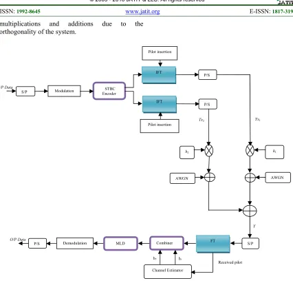
Figure 4 shows the complete model for the proposed STBC-FT-OFDM system with two transmitters and one receiver. The binary input data stream is modulated and mapped to a sequence of modulation symbols after passed through a serial-to-parallel converter. The Alamouti scheme is then applied across two consecutive OFDM symbols within each subcarrier in STBC encoder. According to this coding scheme the signal copy is not only transmitted from another antenna but also at another time. After STBC-encoder the training sequence (pilot subcarriers) is then inserted to allow for channel estimation to be utilized compensating for the channel effects of the required signal. The pilot carrier has a bipolar sequence {±1}. Next, the Nf
-point IFT is applied to the signals to achieve the orthogonality between subcarriers. Zeros are inserted in several bins of IFT to make the transmitted spectrum compact and to decrease adjacent carrier’s interference. Due to the strong overlapping nature of the FT that provides high orthogonality to the processed data, the signal of the proposed system will be transmitted with a higher orthogonality compared with the signal of the traditional OFDM system. Due to the fact that the signal of the proposed system is transmitted with a high orthogonality, there is no need for adding CP to OFDM symbols. Therefore, the proposed system will be with a data rates higher than those in traditional OFDM. Finally, the parallel data are converted into serial via parallel-to-serial (P/S) conversion and sent to the receiver over the wireless channel.
As mentioned in section 2.1 at a given symbol period (t), two OFDM symbols are simultaneously transmitted (s1 and s2) from the two antennas (Tx1and Tx2) respectively, while in the next symbol period (t+T) signal (-s2*) is transmitted from antenna Tx1, and signal s1* is transmitted from antenna Tx2 .The complex fading envelope is assumed to be constant across the corresponding two consecutive time slots.
The received signals from the wireless channel can be described as shown in equations (3, 4), at the receiver side the reverse steps of the encoding processes are employed, a serial to parallel conversion is established and FT with Nf-points is
used to convert the signal from time to frequency domain. The original signals s1 and s2 can be recovered by applying the equations (5, 6, 7, 8) on the received signals (y1 and y2).Then the final data passes through de-mapping technique to recover the original data and are then converted from parallel to serial. To calculate the BER, the received bits are compared to the transmitted bits for various values of energy per bit to noise power spectral density ratio (Eb/No).
[image:5.612.92.521.69.236.2]Figure 5 shows the block diagram of the receiver side for the proposed STBC-FT-OFDM system with two transmitters and two receivers because the transmitter side for this system will be as shown in figure 4. In case of two receivers two signals will received in each time as described in equations (9 and 10) and each signal will converted to frequency domain by using FT after conversion from serial to parallel. Equation 11 will be used to extract s1 and s2 from the received signals y11, y12, y21, and y22.The combiner aided by the channel estimator will provide perfect estimation of the diversity and separate the signals s1 and s2 by simple Figure 3: Analysis And Synthesis Stages Of 1D Single Level Discrete Framelet Transform
(b) Synthesis Stages
h2(n)
h0(n)
h1(n) X(n)
XL(n)
XH1(n)
XH2(n)
2
2
2
(a) Analysis Stages
h0(-n)
h1(-n)
h2(-n)
X(n)
1
2
ISSN: 1992-8645 www.jatit.org E-ISSN: 1817-3195 multiplications and additions due to the
orthogonality of the system.
h2
S/P FT
Combiner
Channel Estimator Demodulation
P/S MLD
Received pilot
O/P Data
h1
Y
STBC Encoder
IFT
P/S
S/P Modulation
h1
AWGN IFT
P/S Pilot insertion
Pilot insertion
h2
AWGN
I/P Data
Tx1 Tx2
Figure 4: STBC-OFDM System With Two Transmitters And One Receiver
h21
S/P FT
Combiner
Channel Estimator Demodulation
P/S
MLD
Received pilot
O/P Data
h11
S/P FT
Combiner h12
h22
Rx1
Rx2
[image:6.612.91.517.65.476.2]MLD
[image:6.612.86.519.538.645.2]ISSN: 1992-8645 www.jatit.org E-ISSN: 1817-3195
5. SIMULATION RESULTS AND
DISCUSSION
The proposed STBC-FT-OFDM system was simulated and tested using MATLAB (version 7.8), and the performance was compared with that of
STBC-FFT-OFDM and STBC-DWT-OFDM
systems in terms of BER. A proposed system equipped with two transmit antennas and arbitrary number of receive antennas. In the simulation scenarios the BPSK and QPSK modulation are used over fading channel. In FT, the coefficients of the transformation matrix with length equal to 7, will be taken as shown in reference [10]. The length of CP in FFT-OFDM was 25% of the total symbol length of OFDM. The fading channel was considered a Rayleigh fading channel modeled as Jake’s model. The effect of the channel was assumed to be constant in each packet frame. All parameters and their values in the systems, which were utilized in this simulation, are shown in Table 2. The results of the simulation for the proposed system with the other systems will be as shown in the following subsections:
Table 2: Simulation Parameters Parameter Value
System Bandwidth (BW) 10MHz
Tsample 0.1µsec
Mapping technique BPSK, QPSK Number of FFT, and FT
points (Nf)
64
Number of useful subcarriers 48
Second path delay , second path gain
16×Tsample , -8dB
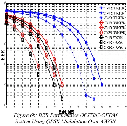
5.1 The Simulation Results Over AWGN Channel
Figures 6a, 6b, show the performance of the proposed STBC-FT-OFDM system compared with that of the STBC-FFT-OFDM and STBC-DWT-OFDM systems using BPSK and QPSK modulation respectively over AWGN channel. Figures 6a and 6b demonstrate that the performance of the proposed system is much better than the other two systems either in case of two transmitters-one receiver or two transmitters-two receivers. Also it is clear from these figures that the performance of the system will be improved as a number of receivers increased with a constant number of transmitters.
5.2 The simulation results Over Flat Fading Channel
In this simulation the signal will be affected by flat fading in addition to AWGN channel where a channel will be with a constant attenuation and linear phase distortion, which has been chosen to have a Rayleigh’s distribution. Figure 7a shows the performance of the proposed systems compared with the other systems using BPSK modulation. This figure showed that the performance of the proposed system is better than the other two systems. The proposed system has BER = 10-3 at Eb/No = 6.25dB for 2Rx and at Eb/No=8.75dB for 0 2 4 6 8 10 12 14 16 18 20 22 24 25 10-5
10-4 10-3 10-2 10-1 100
Eb/No (dB)
B
E
R
[image:7.612.314.522.76.289.2]1Tx-1Rx FFT-BPSK 2Tx-1Rx FFT-BPSK 2Tx-2Rx FFT-BPSK 1Tx-1Rx DWT-BPSK 2Tx-1Rx DWT-BPSK 2Tx-2Rx DWT-BPSK 1Tx-1Rx FT-BPSK 2Tx-1Rx FT-BPSK 2Tx-2Rx FT-BPSK
Figure 6a: BER Performance Of STBC-OFDM System Using BPSK Modulation Over AWGN Channel
0 2 4 6 8 10 12 14 16 18 20 22 24 26 28 30 10-5
10-4
10-3
10-2 10-1 100
Eb/No (dB)
B
E
R
1Tx-1Rx FFT-QPSK 2Tx-1Rx FFT-QPSK 2Tx-2Rx FFT-QPSK 1Tx-1Rx DWT-QPSK 2Tx-1Rx DWT-QPSK 2Tx-2Rx DWT-QPSK 1Tx-1Rx FT-QPSK 2Tx-1Rx FT-QPSK 2Tx-2Rx FT-QPSK
Figure 6b: BER Performance Of STBC-OFDM System Using QPSK Modulation Over AWGN
[image:7.612.314.523.345.553.2]ISSN: 1992-8645 www.jatit.org E-ISSN: 1817-3195 1Rx, while the traditional system has the same BER
at Eb/No= 17dB for 2Rx and at Eb/No=19.75dB for 1Rx, and the STBC-DWT-OFDM system arrives to the same BER at Eb/No = 7dB for 2Rx and at Eb/No= 9.5 dB for 1Rx.
Figure 7b represents the performance of the proposed system compared with the other two systems using QPSK modulation. It is clear from this figure that in the case of STBC-FT-OFDM the Eb/No= 9.5dB and 12.5 dB for 2Rx and1Rx respectively at BER=10-3, while in the case of traditional system the Eb/No=20.75dB and 23.25dB for 2Rx and 1Rx respectively at BER=10-3, and in the STBC-DWT-OFDM system the Eb/No= 10.75dB and 12.5 dB for 2Rx and 1Rx respectively at BER=10-3. So the proposed system has gain about 11.25dB and 10.75dB for 2Rx and 1Rx compared with the traditional system.
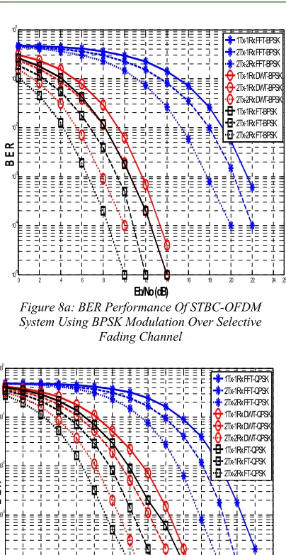
5.3 The Simulation Results Over Selective Fading Channel
Figure 8a and 8b give the BER performance of STBC-OFDM systems in frequency-selective fading channel using BPSK and QPSK modulation respectively, with the second path gain=-8dB and time delay of 16 samples. As seen in these figures the proposed system STBC-FT-OFDM is more robust in the frequency-selective fading channel compared with FFT-OFDM and STBC-DWT-OFDM. Figure 8a showed that the proposed system gave improvement in BER = 10-3 with a gain about (11dB, 11.25dB) for 2Rx and 1Rx respectively compared with the traditional STBC-OFDM, and about (1.25dB, 1.5dB) for 2Rx and 1Rx respectively compared with the STBC-DWT-OFDM system in the case of BPSK modulation. In the QPSK modulation the proposed system outperforms the other two systems with a gain about (10.75dB, 10.25dB) for 2Rx and 1Rx respectively at BER = 10-3 compared with STBC-FFT-OFDM and with a gain about (1.75dB) for 2Rx and 1Rx at BER=10-3 compared with STBC-DWT-OFDM as seen in figure 8b.
0 2 4 6 8 10 12 14 16 18 20 22 24 25 10-5
10-4 10-3 10-2 10-1 100
Eb/No (dB)
B
E
R
[image:8.612.309.520.43.259.2]1Tx-1Rx FFT-BPSK 2Tx-1Rx FFT-BPSK 2Tx-2Rx FFT-BPSK 1Tx-1Rx DWT-BPSK 2Tx-1Rx DWT-BPSK 2Tx-2Rx DWT-BPSK 1Tx-1Rx FT-BPSK 2Tx-1Rx FT-BPSK 2Tx-2Rx FTBPSK
Figure 7a: BER Performance Of STBC-OFDM System Using BPSK Modulation Over Flat Fading
Channel
0 2 4 6 8 10 12 14 16 18 20 22 24 26 28 30 10-4
10-3 10-2 10-1
Eb/No (dB)
B
E
R
1Tx-1Rx FFT-QPSK 2Tx-1Rx FFT-QPSK 2Tx-2Rx FFT-QPSK 1Tx-1Rx DWT-QPSK 2Tx-1Rx DWT-QPSK 2Tx-2Rx DWT-QPSK 1Tx-1Rx FT-QPSK 2Tx-1Rx FT-QPSK 2Tx-2Rx FT-QPSK
Figure 7b: BER Performance Of STBC-OFDM System Using QPSK Modulation Over Flat Fading
[image:8.612.92.291.327.510.2]ISSN: 1992-8645 www.jatit.org E-ISSN: 1817-3195
6. CONCLUSIONS
An STBC-OFDM system based on FT was proposed and compared with STBC-OFDM based on DWT and traditional STBC-OFDM through the use of BPSK and QPSK mapping technique. The performance of the systems was tested and compared in AWGN, flat fading and frequency-selective fading channels. Simulation results indicated that the proposed system has good BER performance compared to that of
STBC-DWT-OFDM and STBC-FFT-STBC-DWT-OFDM. Moreover, the use of CP in traditional system will reduce its spectral efficiency and wastes the transmit power, while in the proposed system, the need for CP is dispensed with because of the excellent orthogonality that is offered by FT, which subsequently reduces the system complexity, increases the transmission rate,
and increases spectral efficiency. This
communication system gives an improvement in system performance and efficient BER vs Eb/No performance. Also it is noticed that for all tested systems the performance of STBC-OFDM with two receivers will be better than the performance of STBC-OFDM with one receiver at a constant number of transmitter.
REFRENCES:
[1] G. Manik, A. Kalra, and S. Kalra, "Performance Analysis of STBC-OFDM System Under Multipath Fading Channel," International Journal of Soft Computing and Engineering, vol. 1, pp. 87-90, 2012.
[2] C.-M. Li, G.-W. Li, and H.-Y. Liu, "Performance Comparison of the STBC-OFDM Decoders in a Fast Fading Channel," Journal of Marine Science and Technology, vol. 20, pp. 534-540, 2012.
[3] S. M. Alamouti, "A simple transmit diversity technique for wireless communications," Selected Areas in Communications, IEEE Journal on, vol. 16, pp. 1451-1458, 1998. [4] N. Kaur, Er.Neetu Gupta, "OFDM-STBC Based
Transceiver for WiMAX 802.16e,"
International Journal of Innovative Research in Computerand Communication Engineering, Vol. 3, Issue 5, May 2015.
[5] L. Yazhen and G. Jing, "Space-time block coded for the OFDM system," in 2012 2nd International Conference on Consumer Electronics, Communications and Networks (CECNet), 2012.
[6] S. Sharma and S. Kumar, "BER Performance Evaluation of FFT-OFDM and DWT-OFDM," International Journal of Network and Mobile Technologies, vol. 2, pp. 110-116, 2011. [7] J. S. Rani and K. A. Chary, "Performance
Comparison of FFT & Dwt Based OFDM with Alamouti Encoding Over Reyleigh Fading Channel."International Journal of Science and Research (IJSR),Volume 3 Issue 11, November 2014.
0 2 4 6 8 10 12 14 16 18 20 22 24 25 10-5
10-4 10-3 10-2 10-1 100
Eb/No (dB)
B
E
R
[image:9.612.98.300.87.478.2]1Tx-1Rx FFT-BPSK 2Tx-1Rx FFT-BPSK 2Tx-2Rx FFT-BPSK 1Tx-1Rx DWT-BPSK 2Tx-1Rx DWT-BPSK 2Tx-2Rx DWT-BPSK 1Tx-1Rx FT-BPSK 2Tx-1Rx FT-BPSK 2Tx-2Rx FT-BPSK
Figure 8a: BER Performance Of STBC-OFDM System Using BPSK Modulation Over Selective
Fading Channel
0 2 4 6 8 10 12 14 16 18 20 22 24 26 28 30 10-5
10-4 10-3 10-2 10-1 100
Eb/No (dB)
B
E
R
1Tx-1Rx FFT-QPSK 2Tx-1Rx FFT-QPSK 2Tx-2Rx FFT-QPSK 1Tx-1Rx DWT-QPSK 2Tx-1Rx DWT-QPSK 2Tx-2Rx DWT-QPSK 1Tx-1Rx FT-QPSK 2Tx-1Rx FT-QPSK 2Tx-2Rx FT-QPSK
Figure 8b: BER Performance Of STBC-OFDM System Using QPSK Modulation Over Selective
ISSN: 1992-8645 www.jatit.org E-ISSN: 1817-3195 [8] A. A. Alansari, "MIMO-OFDM System
Performance Analysis Based on DWT," International Journal of Advanced Science and Engineering Technology On line ISSN, pp. 2225-9686.
[9] S. Kalyanarajan, S. Krithiga, K. Sreedhar, T. Divya, C. S. Parkhi, A. Gupta, et al., "Improving the Transmission Capacity Using Dwt as Multicarrier Modulation for STBC MIMO System."
[10]H. N. Al-Taai, "A novel fast computing method for framelet coefficients," American Journal of Applied Sciences, vol. 5, pp. 1522-1527, 2008. [11]Dr.A.Sabri and T.Abdul_Qader, “New Proposed
Algorithm To Conceals Error In Wireless Image Transmission Based on Framelet Transform". Eng. And Tech. Journal,
vol.28, no.4, 2010.
[12]H. Yuan, X. Hu, and Y. Ling, "Design and simulation of baseband transceiver system based on STBC-OFDM," in Industrial Electronics and Applications, 2008. ICIEA 2008. 3rd IEEE Conference on, 2008, pp. 2400-2405.
[13]H.-C. Jung, C.-J. Kim, J.-H. Kim, and H.-R. Park, "A Comparative Performance Analysis of STBCOFDM Systems Under Rayleigh Fading Environments," Daeduck science town, Republik of Korea: Hankuk Aviation University, 2000.
[14]I. W. Selesnick, "Smooth wavelet tight frames
with zero moments," Applied and
Computational Harmonic Analysis, vol. 10, pp. 163-181, 2001.