item and our policy information available from the repository home page for further information.
To see the final version of this paper please visit the publisher’s website. Access to the published version may require a subscription.
Author(s): Diman, Siti F; Wijeyesekera, D.Chitral
Article title: Swelling Characteristics of Bentonite Clay Mats Year of publication: 2008
Citation: Diman, S.F; Wijeyesekera, D.C. (2008) ‘Swelling Characteristics of Bentonite Clay Mats’Proceedings of the AC&T, pp 179 -185.
Link to published version:
SWELLING CHARACTERISTICS OF BENTONITE CLAY MATS
Siti F. Diman & Chitral Wijeyesekera
Built Environment Research Groupu0628081@uel.ac.uk; d.c.wijeyesekera@uel.ac.uk
Abstract: Bentonite absorbs water to a greater extent than any other ordinary plastic clay and as a consequence it swells depending on the change in its moisture content. This paper aims to give an overview of the swelling characteristic of bentonites with particular observations from that of prehydrated clay mats. How the swelling characteristics vary with the type of clay, water, and the encompassing boundary materials is presented. Accordingly, it examines the swelling response of the clay mat and the pressure exerted when the swelling is both fully and partially restrained. The development of a new apparatus to measure pressures exerted by the clay as a result of the swelling process is also described. A theoretical study is made to postulate how these pressures can be evaluated for field situations. Though bentonites are known to have very high swelling pressures, how this is negated by the compressibility of the composite behaviour with the necessary backfill is demonstrated. Tests show significant differences in swelling behaviour and pressure development when the GCL is in deionized water and sea water environments. Free swell characteristics were similarly affected.. Unique variation of pressure exerted due to swelling in partially restrained conditions was established with experimental observations made during the study.
1. Introduction:
Bentonite is used in the manufacture of geosynthetic clay liners (GCL), which are sealing elements and commonly known as factory-manufactured contaminant / leachate / fluid barriers. These consist of a thin layer (~ 5mm) of either calcium or sodium bentonite core sandwiched between two geomembranes or geotextiles. Design engineers and environmental agencies have developed a growing interest in the application of GCLs as an alternative / preference to compacted clays in cover systems or as bottom lining of waste containment facilities. They have also gained widespread use in variety of sealing applications, predominantly in hydraulic engineering, structural water proofing and groundwater protection. (Wijeyesekera, 2003). In order to meet the demands of an effective contaminant barrier in hostile geochemical environments, a factory controlled prehydration with cation exchange resisting polymer to an
appropriate moisture condition prior to installation is always necessary (McLoughlin, 2004, Wijeyesekera, 2003).
characteristics and the swelling pressure development of Bentonite clay mats under different conditions of volume constraint and geochemical environments. Though these clay liners / mats adequately serve the purpose of being barriers to moisture and leachate movement, engineers are apprehensive that under certain construction circumstances it would be undesirable as they may exert high swell pressures.
Many researchers have proposed and introduced different methods, theories and models to explain the swelling properties and swelling pressure of GCL. However, little attention has been paid so far in the study of the influence of the pressures exerted on structures when the clay swelling is partially or fully restrained and how this pressure is accommodated in field situations.
2. Objectives of the research
The objectives of the research described in this paper are;
• to study the swelling behaviour and the swelling pressure of bentonite clays,
• to observe the significance of volumetric strain on the swell, in order to establish a model for the relationship between pressure and volumetric strain, and
• thus to estimate the magnitude of pressures developed during unrestrained and restrained swelling of the bentonite clay mat in order to develop a sound explanation of the effects of swelling pressure in clay mat - structure interaction
3. Definitions
3.1 Free swell (of montmorillonite)
“Free swell” is defined as the volume occupied by 2gms of the dry clay when
allowed to fully and freely swell in deionised water (figure 3).
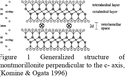
Swelling occurs when clays are allowed free access of water. Since clays possess very high suction within the soil skeleton, these will draw water into the voids causing the volume change in the voids and the soil can then wells and eventually disintegrate. The clay mineral montmorillonite is derived from pyrophyllite through isomorphic replacement of aluminium by magnesium in the octahedral layer (Figure 1) and its ideal chemical formula can be written as ;
n(H2O)cxSi8Al4-xMgxO20(OH)4
The octahedral layer is composed of magnesium and aluminium coordinated in octahedral with oxygen atoms or hydroxyl groups. The silica tetrahedral is interconnected in a silica sheet structure.
Thus the crystallographic structure of montmorillonite is much like a sandwiched deck of cards. Sodium ions located between these platelets allow water to hydrate the clay mineral in an absorption reaction that results in its swelling characteristics. Hence when placed in water, these cards or clay platelets shift apart. Montmorillonite attracts water to its negative charged face elctro
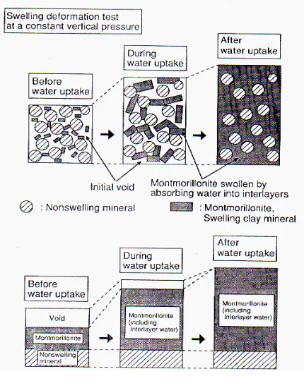
[image:3.595.310.524.510.642.2]Figure 2 Swelling mechanism of montmorillonite (Komine & Ogata 1996)
magnetically to hold the water in place. During hydration, a confined layer of dry bentonite (containing montmorillonite) changes into a dense monolithic mass with no discernable individual particles (Figure 2). This unique characteristic makes the montmorillonite capable of absorbing even up to 7 to 10 times its own weight in water, and consequently swelling up to 18 times its dry volume. reduction in the amount of swell when the clay mat is in sea water. The free swell measurements observed in this study for the clay mat are shown in Figures 4 and 5. There is a distinct environment. The rate of swelling of the clay mat is also faster in the deionised water (Figure 5).
3.2 Swelling pressure
“Swelling pressure” is the pressure required to bring the soil back to its original volume
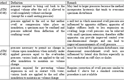
after the soil is allowed to swell without surcharge (see Figure 3). However the term “swelling pressure” is not used or defined consistently throughout the literature. According to O’Conner and Taylor (1994) the definition used is often dependent on what kind of test method is being applied. Brackley (1973) developed three methods for determining the swelling pressure. Each of the three satisfied his definition of swelling pressure but each test also produced a considerably different value. The magnitude of swelling pressure depends on the degree of confinement of the soil; higher degrees of confinement lead to increase in swell pressure. Table 1 (from Day, 2001) shows Johnson’s various definitions of swelling pressure in decreasing order of confinement.
It can be seen from Figure 3, that for a given volumetric strain (v), the pressure (P) exerted by the clay due to the ingress of water can be proposed to be represented by a function in the form
P = f (v) (1)
The f (v) depends on the type of clay and the types of water used. The relevance of this function has been investigated in this study.
4. Instrumentation for swell
pressure measurement
Figure 3.1 – Variation of the pressure exerted by a swelling soil with volumetric strain
Table 1 – Further definitions of swelling pressure (From Day, 2001)
Method Definition Remark
A (ASTM D4546)
pressure required to bring soil back to the original volume after the soil is allowed to swell completely without surcharge
(except for a small seating pressure)
May lead to larger pressures because the method incorporates hysteresis that tends to overcome specimen disturbance
B pressure applied to the soil so that neither
swell or compression takes place on inundation; a specimen may be confined and pressure inferred from deflection of the confining vessel
a null test in which measured swell pressure are influenced by apparatus stiffness; apparatus of higher stiffness leads to less expansion on swelling; large swell pressure can be relieved with small specimen extension; therefore stiffer apparatus can provide improved control over one-dimensional charges and can lead to improved measurements of swell pressure. C
(ASTM D4546)
pressure necessary to permit no change in volume upon inundation when initially under applied pressure equal to the overburden pressure; various loads are applied to the soil after inundation to maintain no volume change
must be corrected for specimen disturbance; one dimensional concolidometr swell tests are influenced by lateral skin friction especially in tests conducted on stiff clays or shales
D pressure required for preventing volume
expansion in soil in contact with water; various loads are applied to the soil after inundation to maintain no volume change
Requires correction of swell pressure similar to method C above but a standard correction procedure is not available
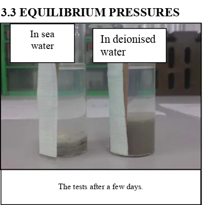
[image:5.595.81.555.354.660.2]3.3 EQUILIBRIUM PRESSURES
Figure 4 Free swelling of clay mat in sea water and deionised water.
0 2 4 6 8 10 12 14
0 1 2 4 5 25 26 46 48
Time (hours)
S
w
elli
ng
(
m
m
)
[image:6.595.309.528.332.431.2]Salt w ater Deionised w ater
Figure 5 Time dependent development of the free swelling of clay mat in sea water and deionised water.
Figure 6 New swell pressure instrumentation
[image:6.595.74.289.386.501.2]developed by the clay sample subjected to the required testing conditions. The apparatus can permit known magnitudes of vertical swell strain. The samples are contained within a stainless steel ring and this generally confines the sample laterally. The upper and lower porous plates on the clay sample allows free access of the water in which the cell is immersed.
Figure 7 illustrates a typical swell pressure development with time, demonstrating again the marked effect of sea water and in this case reducing the swelling pressure (as per the strict definition of no volume strain)
Swelling Pressure of Rawmat Type P
0 2 4 6 8 10 12 14 16
0 50 100 150 200
Time (hr)
S
w
el
li
n
g
P
res
su
re
(
N
/m
m
2 )
Deionized water salt water
Figure 7 Time dependent development of the swell pressure of GCL Rawmat type P in sea water and deionised water.
4.1 Influence of the covering geotextiles
It is interesting to note the repeatability of results (± 5%) with the two deionised water tests as shown in Figure 8. This could be further improved with care been given during the sample preparation and placement stage. The swelling pressure observed for the claymat core only is 410 kPa and 180 kPa in deionised water and sea water respectively. Swelling pressure observations made with the entire clay mat including the covering geotextiles gave lower swelling pressures depending on the type and thickness of the geofabric.
The tests after a few days.
In deionised water
[image:6.595.72.288.387.710.2] [image:6.595.73.287.540.703.2]-100 -500 50 100 150 200 250 300 350 400 450 500
0 10 20 30 40 50 60
Time (hours) P res sur e dev eloped ( K P a)
[image:7.595.75.287.128.274.2]Deionised w ater 1 Salt w ater Deionised w ater 2 Poly. (Deionised w ater 1) Poly. (Salt w ater) Poly. (Deionised w ater 2)
Figure 8 Time dependent development of swelling pressure for the clay mat in deionised water (x2) and sea water.
The sea water persistently reduced the swelling pressure in both cases GCL core with or without covering fabric.
4.2 Influence of permitted vertical strain on the development of the pressure.
Tests were carried out with the core samples being permitted controlled vertical swells of 0.25mm, 0.50 mm and 1.00 mm. The results are shown in Figure 9 and compared with the pressure development when no vertical swell was permitted. Reader’s attention is drawn to the delay time for the pressures to be developed. -50 0 50 100 150 200
0 10 20 30 40 50 60 70 80
Time (hours) Pre ssu re o b se rve d (KPa )
1.00mm 0.50mm 0.25mm comparison
Poly. (1.00mm) Poly. (0.50mm) Poly. (0.25mm) Poly. (comparison)
Figure 9 Swell pressure development with permitted levels of vertical strain.
This is as one would expect the clay core would need to “free swell” by the level of permitted vertical swell. The resulting levels of pressures developed are reduced with the magnitude of the permitted swell. This implies and also explains that any void space / compressibility of the covering geotextiles will reduce the pressure experienced due to swelling. Accordingly for an equilibrium pressure of P; the corresponding deformation of the fabric will be given by the following equation;
f f E A t P v , n
deformatio = …………. (2)
This must comply with the P = f(v) for the clay sample ( figure 3).
4.3 Influence of permitted lateral strain on the development of the pressure.
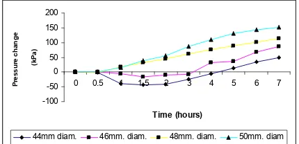
Further tests were done to investigate how the clay core would develop the pressure if it was permitted to swell laterally. In this instance the clay cores were cut to slightly reduced diameters of 48, 46 and 44mm. The diameter of the sample ring is 50mm.
The initiation of the development of pressure appears to be at the same time of 0.5 hours. -100 -50 0 50 100 150 200
0 0.5 1 1.5 2 3 4 5 6 7
Time (hours) P ress u re ch an g e (k P a)
[image:7.595.74.287.570.689.2]44mm diam. 46mm. diam. 48mm. diam. 50mm. diam
[image:7.595.308.523.591.695.2]This is a consequence of the vertical swell. Beyond a permitted 4% lateral strain (see 46 and 44 mm graphs) there is a negative change in vertical pressure indicating a continued softening of the clay due to ingress of water and subsequent lateral squeezing to fill the void of the permitted lateral strain. This happens in the field always during installation as there is no lateral confinement provided to the clay liner and the clay laterally squeezes from the edges of the clay mat in response to ingress of water. The clay squeezing will invariably occur at the free edges and near the overlaps. Far from being detrimental this lateral squeezing of the clay further promotes the sealing at the overlap. These tests further demonstrated that the clay mats when permitted to swell laterally (not restrained horizontally) the maximum pressures developed are very much less than when the samples were confined laterally.
5. CONCLUSIONS
The swelling pressures of bentonite clay mats can be in the order of 400 kPa. However the tests described in this paper has demonstrated that it is significantly decreased with salinity and with any provision to swell (vertically or laterally). Thus the tests described in this paper have helped to conclude the following;
• Clays swell when a fluid is absorbed
• Salt water reduces the swelling and swelling pressures in bentonite clay mats and GCL
• When load is applied, the swelling reduces and the swelling pressure reduces.
• When samples of clays were permitted to swell vertically / laterally the swelling pressures it produced was much lower than the swelling pressure which is observed in samples with no permitted volumetric change.
5. References
Day R. W. 2001. Soil testing manual. Procedures, Classification Data, and sampling Practices Komine H., Ogata N. 1996. Prediction for swelling characteristics of compacted Bentonite Canadian. Geotechnical. Journal vol.33, pp11-17
O’Connor K. and Taylor R.N..1994. The swelling pressure of compacted clayey fill. Project report 72.p.7
McLoughlin, M. 2004. The Influence of Mineralogy and Microstructure on the Contaminant Migration through Geosynthetic Clay Liners. PhD Thesis, University of East London, Department of Civil Engineering, UK.