Security System based on Viola Jones Detection
Sheeba Jeya Sophia.S
Department of Information &Communication Engineering, Anna University Chennai Regional
Center Madurai Madurai, INDIA
Anitha.S
Department of Information &Communication Engineering, Anna University Chennai Regional
Center Madurai Madurai, INDIA
ABSTRACT
Iris recognition is a biometric system for access control that uses the most unique characteristic of the human body, the iris employed in automated border crossings, national ID systems, etc. This paper illustrates techniques to improve performance of iris recognition system based on stationary images using NI LabVIEW (Vision Module). Region of interest segmentation and localization of iris using canny edge detection is performed. And normalization of iris is performed using the Gabor filter. Local Binary Pattern (LBP) is used for feature vectors extraction and Learning Vector Quantization (LVQ) performs classification. Here, matching is performed using the hamming distance. Also we create a LabVIEW database for storing the information of the users. All the images used in this paper were collected from the Chinese Academy Of Sciences Institute of Automation (CASIA) iris database VI.0 with 108 subjects in it.
Index terms----Canny Edge Detection, Gabor Filter, Local Binary Pattern (LBP), Learning Vector Quantization (LVQ).
1. INTRODUCTION
Iris recognition is a rapidly expanding method of biometric authentication that uses pattern- recognition techniques on images of irises to uniquely identify an individual. Iris Code has been extensively deployed in commercial iris recognition systems for various security applications and more than 50 million persons have been enrolled using Iris Code1. Iris-based recognition is the most promising for high-security environments among various biometric techniques (face, fingerprint, palm vein, signature, palm print, iris, etc.) because of its unique, stable, and noninvasive characteristics2. The iris code is a set of bits, each one of which indicates whether a given bandpass texture filter applied at a given point on the iris image has a negative or nonnegative result9. Unlike other biometrics
such as fingerprints and face, the distinct aspect of iris comes from randomly distributed features11. The iris
patterns of the two eyes of an individual or those of identical twins are completely independent and uncorrelated12. Irises not only differ between identical twins, but also between identical twins, but also between the left and right eye. Another characteristic which makes the iris difficult to fake is its responsive nature. Modern cameras used for iris acquisition are less intrusive
compared to earlier iris scanning devices13. Iris detection is one of the most accurate, robust and secure means of biometric identification while also being one of the least invasive. The iris has the unique characteristic of very little variation over a life’s period yet a multitude of variation between individuals.
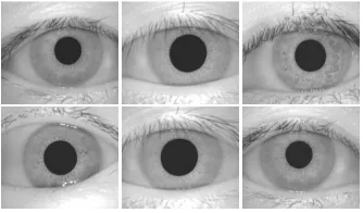
[image:1.612.368.535.375.473.2]Iris recognition system can be used to either prevent unauthorized access or identity individuals using a facility. When installed, this requires users to register their irises with the system. A distinct iris code is generated for every iris image enrolled and is saved within the system. Once registered, a user can present his iris to the system and get identified. Iris recognition technology to provide accurate identity authentication without PIN numbers, passwords or cards. Enrollment takes less than 2 minutes. Authentication takes less than 2 seconds.
Figure 1: Sample of Iris Images
2. RELATED WORK
Daugman made use of multiscale Gabor filters to demodulate texture phase structure information of the iris
4-6
directional subband outputs and extracted the normalized directional energy as features15. Sanchez-Avila et al. further developed the iris representation method by Boles et al. Emergent frequency functions for feature extraction were in essence samples of the phase gradient fields of the analytic image’s dominant components 16,17
.They made an attempt to use different similarity measures for matching, such as Euclidean distance and Hamming distance. Tisse et al.analyzed the iris characteristics using the analytic image constructed by the original image and its Hilbert transform18. The correlation filter of each class was designed using the two-dimensional (2-D) Fourier transforms of training images. If the correlation output (the inverse Fourier transform of the product of the input image’s Fourier transform and the correlation filter) exhibited a sharp peak, the input image was determined to be from an authorized subject, otherwise an imposter. Taking all this facts into consideration, we proposed a methodology to improve the performance of iris recognition systems.
3. METHODOLOGY
[image:2.612.67.287.336.406.2]
Figure 2: Block Diagram of Proposed System
Iris Recognition systems can be explained as follows: (i) Image Acquisition (ii) Iris Preprocessing which includes localization and segmentation (iii) Iris Normalization (iv) Feature Extraction and (v) Matching.
4. LOCALIZATION OF IRIS WITH
CANNY EDGE DETECTION
Canny Edge Detection technique used for segmentation and it is implemented using image management tool in LABVIEW and vision module. Here, after getting the input image, the next step is to localize the circular edge in the region of interest. Canny edge detection operator uses a multi-stage algorithm to detect a wide range of edges in images. It is an optimal edge detector with good detection, good localization and minimal response. In localization we used this detection, in which the inner and outer circles of the iris is approximated, in which inner circle corresponds to iris/pupil boundary and outer circle corresponds to iris/sclera boundary. But the two circles are usually not concentric. Also, comparing with other parts of the eye, the pupil is much darker. The inner boundary is detected between the pupil and the iris. At the same time, the outer boundary of the iris is more difficult to detect because of the low contrast between the two sides of the boundary. So, we detect the outer boundary by maximizing changes of the
perimeter- normalized along the circle. Iris segmentation is an essential process which localizes the correct iris region in an eye image. Circular edge detection function is used for detecting iris as the boundary is circular and darker than the surrounding.
5. NORMALIZATION OF IRIS USING
GABOR FILTER
In normalization, the obtained iris region is transformed in order to have fixed dimensions for the purpose of comparison. Gabor filter is used for the purpose of normalization. It is a linear filter used for edge detection. Here it is used to perform good detection of iris region. The size of the pupil may change due to the variation of the illumination and the associated elastic deformations in the iris texture may interface with the results of pattern matching. And so, for the purpose of accurate texture analysis, it is necessary to compensate this deformation. Since we have detected both inner and outer boundaries of the iris, it is easy to map the iris ring to a rectangular block of texture of a fixed size. Here a convolution filter also employed for the purpose of enhancement. The original image has low contrast and may have non- uniform illumination caused by the position of the light source. These may impair the result of the texture analysis. We enhance the iris image in order to reduce the effect of non-uniform illumination. The one-dimensional Gabor filter is defined as the multiplication of a cosine/sine (even/odd) wave with a Gaussian window as follows,
ge(x)=
cos(2πω0x) (1)
go(x)=
sin(2πω0x) (2) Where, ω0- centre frequency and σ – the spread of the
Gaussian window.
Daugman extended the Gabor filter to two dimensions ge(x)=
cos(2πω
0x+2π ω0y)
(3) go(x)=
(2πω
0x+2π ω0y)
(4)
6. FEATURE EXTRACTION WITH
LOCAL BINARY PATTERN
Local binary patterns (LBP) is a type of feature used for classification in computer vision. LBP was first described in 1994. It has since been found to be a powerful feature for texture classification; it has further been determined that when LBP is combined with the Histogram of oriented gradients (HOG) classifier, it improves the detection performance considerably on some datasets.
Concept of LBP: Input
Image Preprocessing Normalization
Feature
Extraction Enhancement Matching
I
Figure 3: Three neighborhood examples used to define a texture and calculate a local binary pattern (LBP)
The LBP feature vector, in its simplest form, is created in the following manner:
(1) Divide the examined window to cells (e.g. 16x16 pixels for each cell).
(2) For each pixel in a cell, compare the pixel to each of its 8 neighbors (on its top, middle, left-bottom, right-top, etc.). Follow the pixels along a circle, i.e. clockwise or counter-clockwise.
(3) Where the center pixel's value is greater than the neighbor, write "1". Otherwise, write "0". This gives an 8-digit binary number (which is usually converted to decimal for convenience).
(4) Compute the histogram, over the cell, of the frequency of each "number" occurring (i.e., each combination of which pixels are smaller and which are greater than the center).
(5) Optionally normalize the histogram.
(6) Concatenate normalized histograms of all cells. This gives the feature vector for the window.
The feature vector now can be processed using the Support vector machine or some other machine-learning algorithm, to produce a classifier.
Here, features of iris textures are extracted using Local Binary Patterns (LBP). LBP operator forms labels for the image pixels by thresholding the neighborhood of each pixel and considering the result as a binary number. LBP provides fast feature extraction and texture classification. Due to its discriminative power and computational simplicity, the LBP texture operator has become a popular approach in various applications like image retrieval, remote sensing, biomedical image analysis, motion analysis etc…. to extract the entire iris template features. Here, LBP is used to extract the features of the normalized iris image. And so, the output of LBP is feature vectors with n-dimension. Finally this feature vectors are given as input to the LVQ Classifiers.
7. CLASSIFICATION WITH
LEARNING VECTOR
QUANTIZATION
In this paper a Learning Vector Quantization was trained to detect intrusions as the first step. Learning Vector Quantization (LVQ) is a prototype-based supervised classification algorithm. It is a precursor to Self-organizing maps (SOM) and related to neural gas, and to the k-Nearest Neighbor algorithm (k-NN). LVQ was invented by Teuvo Kohonen. Learning vector quantization (LVQ) is a method for training competitive layers in a supervised manner (with target outputs). A competitive layer automatically learns to
classify input vectors. However, the classes that the competitive layer finds are dependent only on the distance between input vectors. If two input vectors are very similar, the competitive layer probably will put them in the same class. There is no mechanism in a strictly competitive layer design to say whether or not any two input vectors are in the same class or different classes. LVQ networks, on the other hand, learn to classify input vectors into target classes chosen by the user. An LVQ network has a first competitive layer and a second linear layer. The competitive layer learns to classify input vectors in much the same way as the competitive layers of Self-Organizing Feature Maps. The linear layer transforms the competitive layer's classes into target classifications defined by the user. The classes learned by the competitive layer are referred to as subclasses and the classes of the linear layer as target classes. Both the competitive and linear layers have one neuron per (sub or target) class. Thus, the competitive layer can learn up to S1 subclasses. These, in turn, are combined by the linear layer to form S2 target classes. (S1 is always larger than S2).
In the training process of LVQ different computational paradigms were used. It is a pattern classification method, in which here each output node is represented as a class. The weight vector of an output node is called a reference or codebook vector. LVQ will classify one main class and neglects the others.
8. MATCHING
Here, matching of two iriscode is performed using the Hamming distance. The Hamming distance gives a measure of how many bits are the same between two bit patterns. Using the Hamming distance of two bit patterns, a decision can be made as to whether the two patterns were generated from different irises or from the same one. In comparing the bit patterns X and Y, the Hamming distance, HD, is defined as the sum of disagreeing bits (sum of the exclusive-OR between X and Y) over N, the total number of bits in the bit pattern
(5) The Hamming distance is the matching metric employed by Daugman, and calculation of the Hamming distance is taken only with bits that are generated from the actual iris region.
9. RESULTS AND DISCUSSION
(a) (b)
(c) (d)
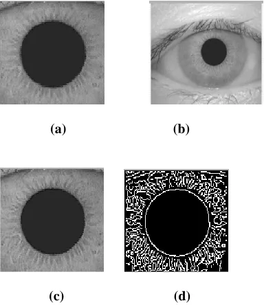
Figure 4: Iris Recognition Process: (a) The original eye image taken from CASIA iris database (b) Region of interest extracted image (c)
Filtered iris image and (d) Edge detected portion of the iris textures
The above figures are the results of iris recognition process. In which, figure 4(a) is the original eye image taken from CASIA iris database. The eye image is processed to segment the region of interest portion as shown if figure 4(b). After this, the extracted image is filtered to get the patterns of clear iris textures as shown in figure 4(c). Figure 4(d) shows the canny edge detected portion of the filtered iris textures. The following figure shows the simulation results of database creation and matching.
[image:4.612.323.545.76.198.2](A) Database Creation
Figure 5: Database Creation
(B) Matching
[image:4.612.74.266.83.305.2]Figure 6: Simulated Output for Matching
[image:4.612.323.544.478.676.2]Figure 7: Simulation Time Taken for Iris recognition
Figure 8: Matching Percent
(C) Performance Plot
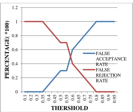
[image:4.612.73.301.502.648.2]Figure 10:Dependence of False Acceptance Rate and False Rejection Rate on threshold
Figure 5 shows database creation, which includes the process of loading an input eye image from database, extracting the region of interest, filtering the extracted image and canny edge detection is used for edge detection. Also the details of user is registered for storing and recognition. Figure 6 is the simulated output for matching, which compares the extracted pattern of the input loaded image with patterns existing in the database. If any of the pattern is matched then it displays “ Mactch occurred” else “No Match”. Figure 7 displays the time taken for the iris recognition process. Figure 8 displays the Matching percentage which incldes number of pixels matched and mismatched and also total number of pixels and using this it calculates the matching percentage. Figure 9 is the performance plot which plots number number of samples in the database versus percentage of match. Figure 10 is plot of false acceptance rate and false rejection rate versus threshold.
10. CONCLUSION AND FUTURE
WORK
In this paper, the iris recogition is discussed by using the NI LabVIEW(VISION MODULE) software. Here, initially input eye images are uploaded from database and region of interest segmentation and localization of iris using canny edge detection is performed. Use of Canny edge detection provides good localization and detection which in turn provides time consumption.Also normalization of iris is performed using the Gabor filter and feature vectors are extracted using Local Binary Pattern (LBP) and Classification is performed using Learning Vector Quantization (LVQ). Here, matching is performed using hamming distance. Also we create a LabVIEW database for storing the information of the users. All the images used in this paper were collected from the Chinese Academy of Sciences Institute of Automation (CASIA) iris database VI.0 with 108 subjects in it.
In future, we planned to enhance this iris recognition systems for real-time images using NI Labview (VISION MODULE). The real-time capturing is possible by use of digital cameras compatible with USB. In which the resolution of camera must be atleast 5 mega pixel and it must be able to process 18 frames/sec for clear capture of images. Here, Viola Jones detection is used for identification of face from captured images. Also, in future we can implement this system in network analysis that is for multi-utility purposes.
11. ACKNOWLEDGMENT
The authors would like to thank the anonymous reviewers for providing constructive comments and suggestions that have contributed to the improvement in the quality and presentation of this paper.
12. REFERENCES
[1]. Adams W. K. Kong, Member, IEEE, David Zhang, Fellow, IEEE, and Mohamed S. Kamel, Fellow, IEEE, “An Analysis of Iriscode”, IEEE transactions on image processing, vol. 19, no. 2, (2010).
[2]. Amol D. Rahulkar and Raghunath S. Holambe, “Half-Iris Feature Extraction and Recognition Using a New Class of Biorthogonal Triplet Half-Band Filter Bank and Flexible k-out-of-n:A Postclassifier”, IEEE Trans. on information forensics and security, vol. 7, no. 1,
(2012),
[3]. Boles .W and Boashash .B , “A human identification technique using images of the iris and wavelet transform”, IEEE Trans. Signal Processing, vol. 46, pp. 1185–1188, (1998).
[4]. Daugman.J, “High confidence visual recognition of persons by a test of statistical independence”,, IEEE Trans. Pattern Analy. Machine Intell., vol. 15, pp. 1148–1161, (1993).
[5]. ---, “Statistical richness of visual phase information: update on recognizing persons by iris patterns”, Int. J. Comput. Vis., vol. 45, no. 1, pp. 25– 38, (2001).
[6]. ---, “Demodulation by complex-valued wavelets for stochastic pattern recognition”, Int. J.Wavelets, Multi-Res. and Info. Processing, vol. 1, no. 1, pp. 1– 17, (2003).
[7]. Flom .L and Safir .A, “Iris Recognition system”, (1987), U.S. Patent 4 641 394, (1987).
[8]. Havlicek .J, Harding .D, and Bovik .A, “The mutli-component AM-FM image representation”,, IEEE Trans. Image Processing, vol. 5, pp. 1094–1100,
(1996).
[9]. Karen P. Hollingsworth, Kevin W. Bowyer, Fellow, IEEE, and Patrick J. Flynn, Senior Member, IEEE, “The Best Bits in an Iris Code”, IEEE Trans. on 0 0.2 0.4 0.6 0.8 1 1.2 0
.1 0.2 0.3
pattern analysis and machine intelligence, vol. 31, no. 6., (2009).
[10].Kumar .B, Xie .C, and Thornton .J, “Iris verification using correlation filters”, in Proc. 4th Int. Conf. Audio- and Video-Based Biometric Person Authentication, pp. 697–705, (2003).
[11].Ma.L, Tan.T, Wang.Y, and Zhang.D, “Efficient iris recognition by characterizing key local variations”, IEEE Trans. Image Process., vol.13, no. 6, pp. 739– 750, (2004).
[12].Monro.D, Rakshit.S, and Zhang.D, “DCT-based iris recognition”, IEEE Trans. Pattern Anal. Mach. Intell., vol. 29, no. 4, pp. 586-595, (2007).
[13].Natalia A. Schmid, Member, IEEE, Manasi V. Ketkar, Harshinder Singh, and Bojan Cukic, Member IEEE, “Performance Analysis of Iris-Based Identification System at the Matching Score Level”, IEEE Trans. on inf. forensics and security, vol. 1, no. 2, (2006).
[14].Yulin Si, Jiangyuan Mei, and Huijun Gao,Senior Member, IEEE, “Novel Approaches to Improve Robustness, Accuracy and Rapidity of Iris Recognition Systems”, IEEE Trans. on Ind. Inf., Vol. 8, no. 1, (2012).
[15].Park .C, Lee .J, Smith .M, and Park .K, “Iris- based personal authentication using a normalized directional
energy feature”, in Proc. 4th Int. Conf. Audio- and Video-Based Biometric Person Authentication, pp. 224–232, (2003).
[16].Sanchez-Avila .C and Sanchez-Reillo .R, “Iris-based biometric recognition using dyadic wavelet transform,” IEEE Aerosp. Electron. Syst. Mag., vol. 17, pp. 3–6, (2002).
[17]. Tangsukson .T and Havlicek .J, “AM-FM image segmentation”, in Proc. EEE Int. Conf. Image Processing, pp. 104–107, (2000).
[18].Tisse .C, Martin .L , Torres .L , and Robert .M, “Person identification technique using human iris recognition”, (2002), in Proc. Vision Interface, pp. 294–299, (2002).
[19]. Paigwar Shikha and Shukla Shailja,” Neural Network based Offline Signature Recognition and verification system”, Research Journal of Engineering Science 2(2) 11-15, (2013).
[20].Singh Amarendra and Verma Nupur,”Ear Recognition for automated Human Identification “ , Research Journal of Engineering Science 1(5) 44-46, (2012).