© 2016, IRJET ISO 9001:2008 Certified Journal Page 2324
Modeling and Analysis of Aqueduct using Staad. Pro
Naveen Shukla
1,
Zalakkumar R. Chhaya
2,Partik A. Parekh
3,
1
PG student, Master of Structural engineering - HJD_ITER- KERA (KUCHCHH), Gujarat, India
2
Assistant Professor, Dept. of civil Engineering, L. D. College of Engineering, Ahmedabad, Gujarat, India
3
Assistant Professor, Dept. of civil Engineering - HJD_ITER- KERA (KUCHCHH), Gujarat, India
---***---Abstract -
Present paper deals with modeling and analysis of aqueduct structure in Staad. Pro. An attempt is made to model aqueduct in software and results are observed with given loading condition.Aqueduct is a cross drainage structure carrying canal supported with piers which concerned with river current. In the paper loading actiong on barrels and stresses are observed after analysis.
In the paper loadings are mainly acting on the barrels are considered to check behavior of the barrel. Seismic static loading is applied by the virtue of self weight and other loadings.
Key Words : Aqueduct, barrel, Hydrostatic loading, stresses, Earthquake loading
1. INTRODUCTION
Whenever a canal crosses a natural drainage on its passage it is necessary to construct masonry works to dispose of drainage discharge so that the canal water supply continues uninterrupted. These masonry works are termed as cross drainage works
Canal are generally aligned on the watershed so that they meet minimum number of drain. However, before watershed is reached, they usually cross a number of drainage lines. At the watershed itself cross a number of local drainage. A canal system taking off from a large river may irrigate area comprising a number of doabs or area between different streams.
In this paper under a fix set of input aqueduct is analysed as beam element and plate elements.
2. Types of Drainage Works
Drainage water intercepted by a canal may be disposed of by any one of the following method:
1. By passing the irrigation canal over the drainage .This is achieved through
1. An aqueduct or 2. A syphon aqueduct
2. By passing the drainage over the canal. This is achieved through:
1.
A super passage2.
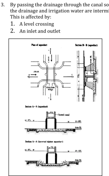
A syphon.3. By passing the drainage through the canal so that the drainage and irrigation water are intermixed. This is affected by:
1.
A level crossing2.
An inlet and outletFig -1: Aqueduct layout of structure
3.
Input data and Design of aqueduct
In this section following is the manual design of
aqueduct for the canal and drainage levels as described
below:
i Canal discharge 39.8 cumec
ii Bed width of canal 13.0 m
iii Water depth 2.4
iv Total head loss (entry 0.033,aqueduct 0.132m and exit 0.065m total 0.23m)
v Upstream bed level
[image:1.595.325.535.202.540.2]© 2016, IRJET ISO 9001:2008 Certified Journal Page 2325 vi Downstream bed
level of canal 70.23-0.23=70.76 vii Manning ‘s rugosity
coefficient 0.016
viii Side slope of canal 1.5:1
ix Bed level of river 62.79m x Ground level on the
u.s side of river bed 67.24m
xi Ground level on d.s
of river bed 66.875m
xii Maximum flood
level in river 71.16m xiii Maximum discharge
in the river 1025m^3\s
Xiv Maximum water
[image:2.595.52.256.587.730.2]table level at site 64.28m
Table -1: Input data
3.1 Design
Span between piers = 13.70 m Span between bearing = 12.95m Trough dimensions = 6*3.2 Free board = 0.8m
(i) Weight of upper and lower slab = 0.4*2.4=0.96 t\m
(ii) Water thrust at sides: water depth =2.8 m upto lower bed of trough; pressure =2.8t\m
(iii) Water load on bottom slab = 1*2.8*1=2.8 t\m (iv) Weight of wearing coat 0.075*2.4 t/m
The maximum load as per IRC class A loading is ( 5.7 t per 1.83m)
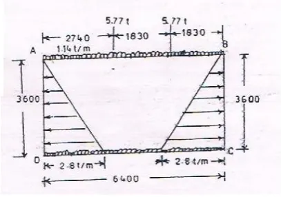
For the design of trough section 5.7t AB=CD =6.4m; BC =AD =3.6. The load for maximum bending moment will be as per following fig.
Fig -2: Load Diagram for the Barrel
(a) Member AB
B.M for uniformly distributed load;
Ma = Mb = WL2/12 = 1.14*6.42/12 = 3.9 tm Calculation for point load B.M
Ra = 5.7 * (5.49/6.4) =4.t Rb = 2*5.7 – 4.9 = 6.5 t Mp = 4.9 * 2.74 = 13.4 tm MQ = 6.5 *1.83 = 11.9 tm
P is point of application of left 5.7 t Q is point of application of right 5.7 t
By using of moment distribution method the calculating base and span moments due to concentrated
and distributed loads we get moment and shear as below ;
Member support span Shear force t
AB 10.283 9.46 10.31
BC 11.485 2.336 9.41
CD 11.485 8 12.1
DA 11.202 2.336 9.04
Table -2: Maximum moments and shear in different member of the box
3.2 Design of box section
Use of M20 concrete will be made ; permissible stress in concrete = 50 kg/cm2
Permissible stress in bending = 70kg/cm2 ; q = 7 kg/cm2 tor steel will be used
The following stresses in reinforcement will be taken in design
(i) Direct tensile strength = 1500 kg/cm2 (ii) Bending tensile strength = 1500kg/cm2
(iii) Tensile stress in member 225 mm or thick and away from water face ,in bending 1900 kg/cm2
(iv) Tensile stress in shear in shear reinforcement for member 225 mm or more in thickness under shear = 1750 kg/cm2
Modular ratio = 2800/3 * permissible stress in concrete in bending compression
© 2016, IRJET ISO 9001:2008 Certified Journal Page 2326
Table -3: Maximum moments and shear in different member of the box
Fig -3: Reinforcement & Shear Diagram
4.ANALYSIS AND 3D MODELING
In this paper it is aimed to observe analysis results for fixed discharge and geometrical conditions
Modeling is carried out as per following:
(a) Taking geometry as beam element.
The solution of problem is derived by simplifying it as beam elements and analyzed under various loadings and according shear force and bending moment evaluated.
(b) Modeling the aqueduct with thre dimensional geometry.
In this action whole aqueduct is analyzed by modeling it under different loading condition and actual element such as plate and then analyses / design.
Loadings we taken or various element as described in IS 7784-1993 Part 1
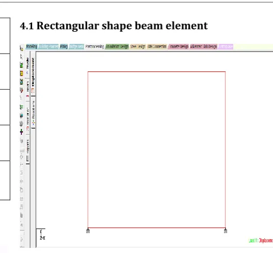
4.1
Rectangular shape beam element
Fig -4: Rectangular model
4.3
Rectangular shape bending moment
Fig -5: Bending moment
Member Face Desired reinforcement
Provided reinforcement cm2
AB Inside
Outside
20.70 (span)
17.5(support)
24.5
21.75
CD Inside
Outside
25.2(support)
13.5(span)
25.75
20.10
BC Inside
Outside
25.2(support)
3.95(span)
27.625
5.5
AD Inside
Outside
25.2(support)
3.95(span)
27.625
[image:3.595.38.295.324.449.2] [image:3.595.304.546.426.613.2]© 2016, IRJET ISO 9001:2008 Certified Journal Page 2327
4.4
Trapezoidal shape
Fig -6: Trapezoidal model
4.5 Bending moment
Fig -7: Bending moment
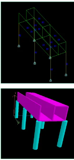
4.6
Analysis of rectangular shape Aqueduct with 3D
modelling
[image:4.595.39.586.105.764.2] [image:4.595.308.564.142.690.2]© 2016, IRJET ISO 9001:2008 Certified Journal Page 2328
Fig -8: Load diagram
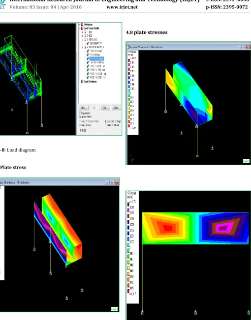
4.7 Plate stress
Fig -9: Plate stresses due to barrel loading
4.8
plate stresses
[image:5.595.52.563.57.709.2] [image:5.595.34.572.367.699.2]© 2016, IRJET ISO 9001:2008 Certified Journal Page 2329
5.CONCLUSION
From the analysis, for the given data following points are concluded:
1. For rectangular cross section, Maximum moment is in top horizontal member as 107 kN.m (Sagging) and support moment as 108 kN.m ( negative) in bottom member.
2. For Trapezoidal cross section, Maximum moment is in top horizontal member as 131 kN.m (Sagging) and support moment as 133 kN.m ( negative)
3. In case of Bending stresses due to self weight, hydrostatic loading, Vehicular loads, it is observed that maximum stress concentration at centre in bottom slab is 1.53 kN m/m and minimum 0.29 kN m/m. Also free end of wall concentrated with 77.9 kN m/m at top portion.
4. In case of Shear stresses due to EQX loading, it is observed that maximum stress concentration in Right hand side wall at centre 0.015 kN m/m and minimum 0.012 kN m/m.
ACKNOWLEDGEMENT
I am pleased to publish the paper titled “Modelling and analysis of aqueduct using Staad. Pro”. I am highly thankful to my guide for providing guidance as and when required. I also thankful to my college for giving opportunity to carry out the work.
REFERENCES
[1] R.S.Varshney, S.C.Gupta & R.L.Gupta, Theory and Design
of Irrigation Structures Canal & Storage Works (Vol. II), 5th Edition, Nem Chand & Brothers.
[2] N.Krishna raju, Design of bridges, 4thEdition, Oxford
&IBH Publishing.
[3] IS Code 7784, Code of practice for design of Cross
drainage work, Part 2 specific requirements, and Section 2 Super passages.
[4] IS Code 3370, Code of practice for concrete structure for
storage of liquid, Part 1
[5] IS Code 0456, Code of practice for plain & reinforced
concrete structure.
[6] IS Code 0456, Design aid for reinforced concrete.
[7] IS Code 7784, Design of cross drainage cross work part
2
[8] IS Code 7784, Design of cross drainage cross work part