http://dx.doi.org/10.4236/cs.2016.710253
Comparison and Performance Analysis
of FACTs Controller in System Stability
Karthikeyan Ramasamy
Department of Electrical and Electronics Engineering, M. Kumarasamy College of Engineering, Karur, India
Received 18 April 2016; accepted 5 May 2016; published 16 August 2016
Copyright © 2016 by author and Scientific Research Publishing Inc.
This work is licensed under the Creative Commons Attribution International License (CC BY). http://creativecommons.org/licenses/by/4.0/
Abstract
In large inter connected power systems, inter-area oscillations are turned to be a severe problem. Hence inter-area oscillations cause severe problems like damage to generators, reduce the power transfer capability of transmission lines, increase wear and tear on network components, increase line losses etc. This paper is to maintain the stability of system by damping inter-area oscillations. Implementation of new equipment consists of high power electronics based technologies such as FACTs and proper controller design has become an essential to provide better damping perfor-mance than Power System Stabilizer (PSS). With development of Wide Area Measurement System (WAMS), remote signals have become as feedback signals to design Wide Area Damping Controller (WADC) for FACTs devices. In this work, POD is applied to both SVC and SSSC. Simulation studies are carried out in Power System Analysis Toolbox (PSAT) environment to evaluate the effective-ness of the FACTs controller in a large area power system. Results show that extensive analysis of FACTs controller for improving stability of system.
Keywords
Power System Stabilizer, Wide-Area Measurement System, Wide-Area Damping Controller, Static VAR Compensator, Flexible AC Transmission System, Power Oscillation Damper, Static Synchronous Series Compensator
1. Introduction
contempora-neously in operation, each one with its own internal dynamics, which however interacts with each other, giving rise to a complex collective behavior. The wide geographic extension of electric power systems that can span entire countries and even continents adds complexity to the issue connected to their analysis and control [1].
Power system stability is the ability of an electric power system for a given initial operating conditions to re-gain a state of operating equilibrium after being subjected to a physical disturbances, with most of the system variables being bounded. So that practically the entire systems remain intact. Power system stability can be clas-sified as voltage stability, rotor angle stability and frequency stability. Among these types, inter-area oscillation comes under rotor angle stability [2]-[4].
For any given situation, the rotor angle stability of the system depends on whether or not the deviations in angular positions of the rotors result in sufficient restoring torque. Loss of synchronism can occur between one machine and the rest of the system, or between groups of machines, with synchronism maintained within each group after separating from each other. The change in electromagnetic torque of a synchronous machine follow-ing a perturbation can be resolved into two components [2] [4] [5]:
Synchronizing torque component, in phase with rotor angle deviation. Damping torque component, in phase with the speed deviation.
If oscillation occurs between a large group of machines and rest of the system then such kind of oscillations are known as inter-area mode or local mode oscillations. These oscillation frequencies range from 0.1 HZ to 0.8 HZ. In order to damp such electromechanical oscillations traditionally we use Power system stabilizers on ge-nerator excitation control system. Power system stabilizers are effective but usually they are designed for local modes and in large power systems they cannot able to provide enough damping for inter-area modes [1] [6] [7].
In this paper, Static Var Compensator (SVC), a shunt FACTs device and Static Synchronous Series Compen-sator (SSSC), a series FACTs device have been widely used in power systems. SVC can increase the transmitta-ble power by regulating the voltage and damping the power oscillations. SSSC can provide real power composi-tion. While the main purpose FACTs device is to provide real and reactive power compensation, a proper sup-plementary control signal to FACTs controller can provide damping to inter-area oscillations. Damping of inter- area oscillations is evaluated in PSAT software. The output of both fault conditions and fault condition with FACTs controller of power system is obtained with time domain specifications.
2. Power System under Study
In this study the well-known New England 10-machine 39-bus test power system is employed as examples for large power systems, to demonstrate the proposed approach. Test systems were implemented using the software tool Power System Analysis Toolbox (PSAT) via the PSAT Simulink library as shown below, implementing the New England 39-bus test system in PSAT.
In this sub-section, the New England 10-machine 39-bus test system implementation in PSAT is completely described. It should be emphasized that the methodology of the proposed approach is applicable to any other system in a similar manner. Synchronous machines are initiated after power flow computations.
A PV or a slack generator is required to impose the desired voltage and active power at the machine bus. Synchronous machines controls such as AVRs or Turbine Governors are not included in the machine models. Furthermore, the voltage ratings of all system equipments in kV need to be specified in PSAT environment. However, the New England 39-bus test systems data are provided based on per unit values. The voltage ratings for all machines were decided to be 400 kV. Then, the voltage ratings of the other equipments were chosen ac-cording to the existing transformers in the system [2] [3] [8].
The slack generator (bus 1) is directly connected to the system without any transformer. Therefore, based on the voltage ratings chosen for the system equipments, the slack generator should be connected to a 400 kV bus, that indeed there is no generator working with this voltage level in practice. Each generator was described by a two-axis fourth-order model with a uniform damping (k = Di/Mi) equal to 0.01. Besides one slack bus and 9 PV
buses, the test system consists of additional 30 PQ buses. However, only 19 buses in the system have nonzero real and reactive loads. All loads were modeled as constant impedance model.
3. FACTs Controller Design
Power Oscillation Damper (POD) together with their coordination of FACTs device has been developed for en-hancing system stability. However, the use of POD may not be, in some cases, effective in providing sufficient damping for inter-area oscillations, particularly with increasing transmission line loading over long distances. Drawing on the availability of FACTs devices at present, which have been developed primarily for active power and/or reactive power flow and voltage control functions in the transmission system, more effective measures have been proposed for improving system damping. Proposed an optimization based technique for control coor-dination of POD and FACTs controllers for optimal oscillations damping in multi-machine power system. Damping of power system oscillations between inter connected areas is very important for the system secure operation [5] [9] [10].
POD co-ordinates with FACTs devices are used to enhance system stability. In large power systems, using only conventional POD may not able to provide sufficient damping for inter-area oscillations. In these cases FACTs power oscillation damping controllers are effective solutions. But uncoordinated local control of FACTs devices and POD may cause destabilizing interactions in power system.
In optimization based approach has been suggested for power system optimization and coordination of FACTs controllers to a significant transient stability improvement and effective power oscillation damping. The problem of poorly damped, low frequency oscillations, associated with the generator rotor swings has been a matter of concern to power engineers for a long time. Damping of electro-mechanical oscillations between in-terconnected synchronous generators is necessary for secure system operation. This increases the operational dynamic stability margin of power system [7] [11].
3.1. Characteristics of SVC Controller
A static VAR compensator (SVC) is a shunt connected static VAR generator or absorber whose output is ad-justed to exchange capacitive or inductive current so as to maintain or control specific variables of the electrical power system (typically bus voltage) [12] [13]. A typical topology of SVC comprises a parallel combination of a thyristor controlled reactor and a fixed capacitor as shown inFigure 1.
3.2. Characteristics of SSSC Controller
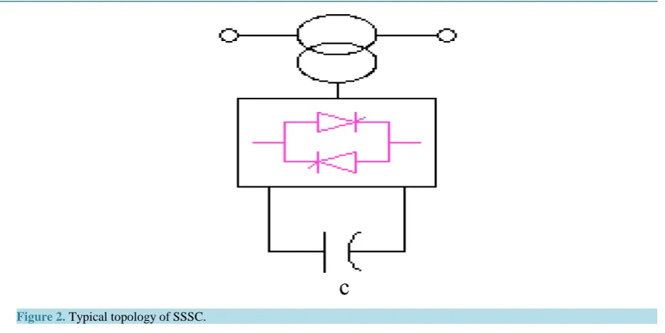
A transmission line needs controllable compensation for power flow control and voltage regulation. This can be achieved by FACTS controllers. SSSC is a series connected FACTS controller, which is capable of providing Real Power compensation to a Power System. The output of an SSSC is series injected voltage, which leads or lags line current by 90˚, thus emulating a controllable inductive or capacitive reactance [14] [15]. SSSC can be used to reduce the equivalent line impedance and enhance the active power transfer capability of the line SSSC is a voltage source controlled based series FACTS device that provides capacitive or inductive compensation independent of line current .Typical Topology of SSSC is shown in Figure 2.
Figure 2. Typical topology of SSSC.
3.3. Design of Power Oscillation Damper
To damp electromechanical oscillations in power system, supplementary control action can be applied to some FACTs devices to increases the system damping. The supplementary control is called power oscillation damping (POD). Since the FACTs devices are located in transmission systems, local input signals are always preferred, usually the active or reactive power allow through the FACTs device. POD control is applied very often on PSS. In that case the local rotor speed is the input signal for POD controller [14] [15].
Figure 3shows the closed-loop system where G(s) represents the power system and H(s) the FACTs POD controller and it consists of an amplification block, a wash-out and a low-pass filters and mc stages of lead-lag blocks. The transfer function, H(s) of the POD controller is given by Equation
( )
1( )
1 1
1 1 1
mc
W lead
m w lag
ST ST
H s K K s
ST ST ST
+
= =
+ + + . (1)
K is a positive constant gain and H(s) is the transfer function of the wash-out and lead-lag blocks. Tm is a measurement time constants and Tw is the washout time constant. Tlead and Tlag are the lead and lag time constant respectively. 1 sin 1 sin comp lead c c comp lag c T m T m φ α φ − = + (2) 1 lag c T ω α
= (3)
lead lag c
T =T
α
(4)where mcis the number if compensation stages (usually mc= 2).
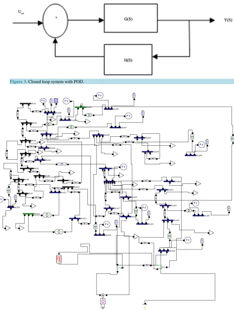
4. Test System Description (Figure 4, Figure 5)
[image:4.595.262.350.523.631.2]Figure 3. Closed loop system with POD.
Figure 4. Simulation diagram of 39-bus system with SVC controller. Bus9
Bus8
Bus7 Bus6
Bus5 Bus4
Bus39
Bus38 Bus37
Bus36
Bus35 Bus34
Bus33
Bus32 Bus31
Bus30
Bus3
Bus29
Bus28
Bus27 Bus26
Bus25
Bus24
Bus23 Bus22 Bus21 Bus20
Bus2
Bus19 Bus18
Bus17 Bus16 Bus15 Bus14
Bus13 Bus12
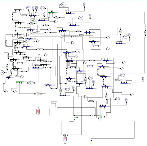
Figure 5. Simulation diagram of 39-bus system with SSSC controller.
5. Results and Discussion
5.1. System with Fault
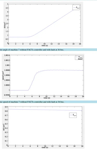
In order to simulate the system behavior under large disturbance conditions (with fault at bus 36 where machine 7 is connected) without FACTs controller.
5.2. System with FACTs Controller
In order to simulate the system behavior under large disturbance conditions (With fault at bus 36 where machine 7) with FACTs controller.
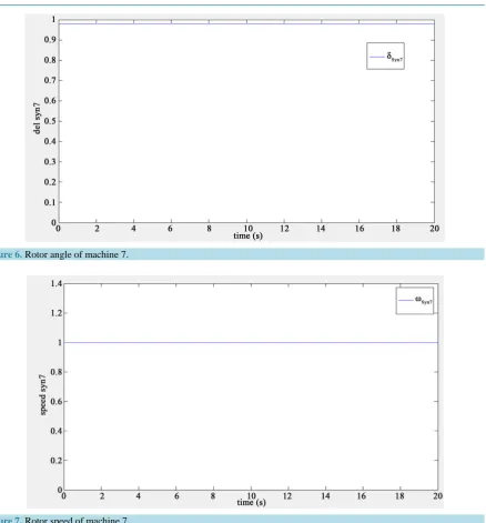
Figure 6 and Figure 7 clearly depict that there is no deviation in the rotor angle and there is no speed devia-tion in the machine 7 when there is no fault in the system. If the fault is introduced in the system at the bus 36, a
Figure 6. Rotor angle of machine 7.
Figure 7. Rotor speed of machine 7.
machine 7 connected to the bus 36 oscillates due to insufficient damping torque and insufficient synchronizing torque. When such oscillations persists it will causes steady increase in rotor angle and speed of machine and it results instability. In order to maintain the stability of system, these oscillations are damped as quickly as possi-ble. The results, due to the fault are shown inFigure 8 and Figure 9.
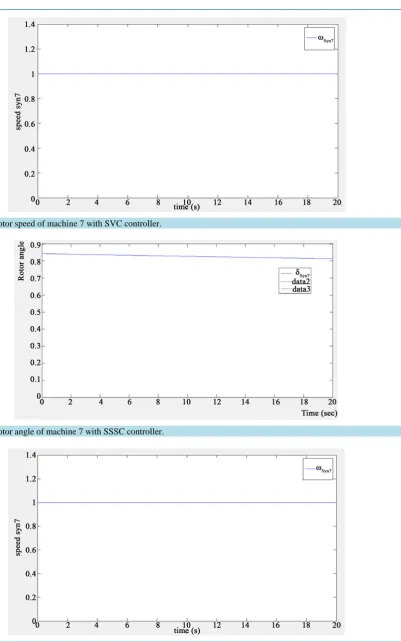
PSSs damp the inter-area oscillations by changing the excitation of the system and it takes more time to damp these oscillations. FACTs controller provide better damping compared to PSSs. The results with SVC controller are shown in Figure 10 and Figure 11. The results with SSSC controller are shown in Figure 12 and Figure 13. SVC and SSSC FACTs controller retain the stability of the system by damping the inter-area oscillations can be compared by using the results.
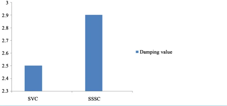
5.3. Comparison of SVC and SSSC Controller
Figure 8. Rotor angle of machine 7 without FACTs controller and with fault at 36 bus.
Figure 9. Rotor speed of machine 7 without FACTs controller and with fault at 36 bus.
Figure 11. Rotor speed of machine 7 with SVC controller.
[image:9.595.143.534.463.709.2]Figure 12. Rotor angle of machine 7 with SSSC controller.
Figure 14. Comparison of SVC and SSSC controller.
6. Conclusion
The enhancement of rotor angle stability in a power system is done by using different FACTs Controllers and it is analyzed with the help of PSAT software. The New England 10-machine 39-bus test power system was used as examples to demonstrate the proposed approach. The results show that the power system oscillations are damped out very quickly with the help of SVC and SSSC based damping controllers in few seconds. These re-sults show that the use of SVC or SSSC is improved dynamic response and at the same time faster than other conventional controllers. Moreover, this approach is also simple and easy to be realized in power systems.
References
[1] Das, T.K., Jetti, S.R. and Venayagamoorthy, G.K. (2006) Optimal Design of SVC Damping Controllers with Wide Area Measurements Using Small Population Based PSO. 2006 International Joint Conference on Neural Networks, Vancouver, 16-21 July 2006, 2255-2260. http://dx.doi.org//10.1109/IJCNN.2006.247022
[2] Singh, B. (2011) Applications of FACTS Controllers in Power Systems for Enhance the Power System Stability: A State-of-the-Art. International Journal of Reviews in Computing, 6, 40-69.
[3] Boroujeni, H.F., Eghtedari, M., Memaripour, A. and Behzadipour, E. (2011) The Designed HS Based Stabilizer Is Ex-erted to Damping LFO in Study System. Indian Journal of Science and Technology, 4, No. 12.
[4] Kundur, P. (1994) Power System Stability and Control. McGraw-Hill, New York.
[5] Karami, A. and Esmaili, S.Z. (2012) Transient Stability Assessment of Power Systems Described with Detailed Models Using Neural Networks. International Journal of Electrical Power and Energy Systems, 45, 279-292.
http://dx.doi.org//10.1016/j.ijepes.2012.08.071
[6] Chaudhur, B., Majumder, R. and Pal, B.C. (2004) Wide-Area Measurement-Based Stabilizing Control of Power Sys-tem Considering Signal Transmission Delay. IEEE Transactions on Power SysSys-tems, 19, No. 4.
http://dx.doi.org/10.1109/tpwrs.2004.835669
[7] Chow, J., Sanchez-Gasca, J., Ren, H. and Wang, S. (2000) Power System Damping Controller Design Using Multiple Input Signals. IEEE Control System Magazine, 20, 82-90. http://dx.doi.org/10.1109/37.856181
[8] Sharma, N.K. and Ghosh, A. (2003) A Novel Placement Strategy for FACTs Controllers. IEEE Transactions on Power Delivery, 18, No. 3. http://dx.doi.org/10.1109/TPWRD.2003.813874
[9] Padiyar, K.R. (2002) Power System Dynamics—Stability and Control. 2nd Edition, B.S. Publications, Hyderabad.
[10] Noroozian, M., Ghandhari, M., Andersson, G., Gronquist, J. and Hiskens, I. (2001) A Robust Control Strategy for Shunt and Series Reactive Compensators to Damp Electromechanical Oscillations. IEEE Transactions on Power Deli-very, 16, No. 4. http://dx.doi.org/10.1109/61.956774
[11] Hammad, A.E. (1986) Analysis of Power System Stability Enhancement by Static VAR Compensators. IEEE Transac-tion on PWRS, 1, 222-227. http://dx.doi.org/10.1109/TPWRS.1986.4335049
[12] Farsangi, M.M., Nezamabadi-pour, H., Song, Y.-H. and Lee, K.Y. (2007) Placement of SVCs and Selection of Stabi-lizing Signals in Power Systems. IEEE Transactions on Power Systems, 22, No. 3.
ducting Magnetic Energy Storage Integrated System. International Journal of Engineering and Advanced Technology (IJEAT), 2, No. 3.
[14] Abido, M.A. (2004) Analysis of Power System Stability Enhancement via Excitation and Facts-Based Stabilizers. Electric Power Components and Systems, 32, 75-91. http://dx.doi.org/10.1080/15325000490196915
[15] Noroozian, M. and Andersson, G. (1994) Damping of Power System Oscillations by use of Controllable Components. IEEE Transaction on Power Delivery, 9, No. 4. http://dx.doi.org/10.1109/61.329537
Submit or recommend next manuscript to SCIRP and we will provide best service for you:
Accepting pre-submission inquiries through Email, Facebook, LinkedIn, Twitter, etc. A wide selection of journals (inclusive of 9 subjects, more than 200 journals) Providing 24-hour high-quality service
User-friendly online submission system Fair and swift peer-review system
Efficient typesetting and proofreading procedure
Display of the result of downloads and visits, as well as the number of cited articles Maximum dissemination of your research work