Study of Coordination between Protective Devices
Comprising Distributed Generation in Distribution System
Sujarit Muangchareon1, Atthapol Ngaopitakkul1, Sulee Bunjongjit1, Monthon Leelajindakrairerk1, Chaichan Pothisarn1, Auttarat Nawikavatan2
1
Department of Electrical Engineering, Faculty of Engineering, King Mongkut’s Institute of Technology Ladkrabang, Bangkok, Thailand
2
Department of Electrical Engineering, Faculty of Engineering, South-East Asia University, Bangkok, Thailand Email: [email protected]
Received April, 2013
ABSTRACT
This paper proposes to study the coordination of protective devices when 8 MW synchronous generators are intercon-nected to distribution System of PEA. The coordination between recloser and drop out fuse is investigated in this paper. The three-phase fault is simulated using digital simulation and electrical network calculation program (DIgSILENT). The results are shown that the short circuit current from substation is reduced comparing to the distribution system without DG connected. It causes to protective device coordination inconsistently, so the maintenance will be delayed more than expected.
Keywords: Coordination; Distributed Generation; Protective device; Renewable Energy
1. Introduction
Nowadays, many countries have been promoting the em-ploying of renewable energy in order to produce electric-ity by distributed generation (DG). DG is a kind of natu-ral energy such as solar energy, wind energy, biomass, and etc., used in the power industry with different tech-nologies. Generally, the distribution scheme of Thailand is a radial system, which the current flows in one direc-tion. However, with the employment of DG into the dis-tribution system, there are many issues [1-5] that may cause the technical impacts to the distribution system. Electrical power protection is one of problems that is interested. When DG is connected to distribution system, it affects the performance of the system and the protec-tive device that is already installed owing to the change of level voltage, short-circuit level and direction of pow-er flow in the system. For this reason, protective device may cause the malfunction due to the bus impedance of the system is changed; this will result in change of the current of each bus.
In the literature for DG, fault analysis and protective device have been developed to be used in the protection distribution system [5-12]. The impact of DG on arcing faults is proposed in [5]. A solution for the short-circuit calculation in the network with the DG, which takes into account the arc resistance existing at the fault location is presented by R. Ciric et al. [5]. The result shows that the
arc increases the impedance measured by the protection device, whereas the DG can be increased the fault current, decreased the arc resistance, and decreasing the impact of arc on the impedance measured by the protection device. A combination of Wavelet Transform and S-Transform [7] has been introduced to detection of islanding event and PQ disturbances in grid-connected hybrid power system. The intelligent relay, as introduced in [9], is viewed as passive islanding protection. This technique proposed relay setting by using both dependability and security performance indices; the latter is particularly important for minimizing nuisance tripping for larger DG penetration levels. A new passive islanding detection technique using the rate of change of phase angle differ-ence (ROCPAD) is proposed by Ankita Samui et al. [12]. The response time of ROCPAD is within one cycle from the event inception, showing fastness of the proposed algorithm compared to ROCOF relays and working ef-fectively in the situations where ROCOF fails.
2. Fault Calculation According to IEC
609090
The method used for calculation is based on the intro- duction of an equivalent voltage source at the short-cir- cuit location. The equivalent voltage source is the only
active voltage of the system as shown in Figure 1. All
network feeders, synchronous and asynchronous ma-chines are replaced by their internal impedances.
The current of three-phase short circuit following IEC60909 can be calculated by equation 1.
IF = V/(Z1 + ZF) (1)
when, V = voltage
Z1= positive sequence impedance
ZF = fault impedance
3. Power System Simulation using
DIgSILENT
DIgSILENT is a computer aided engineering tool for the simulation and analysis of power systems. DIgSILENT powerfactory is employed to simulate behaviour and co-ordination of protective device when distributed genera-tion (DG) is connected to 22kV distribugenera-tion system as
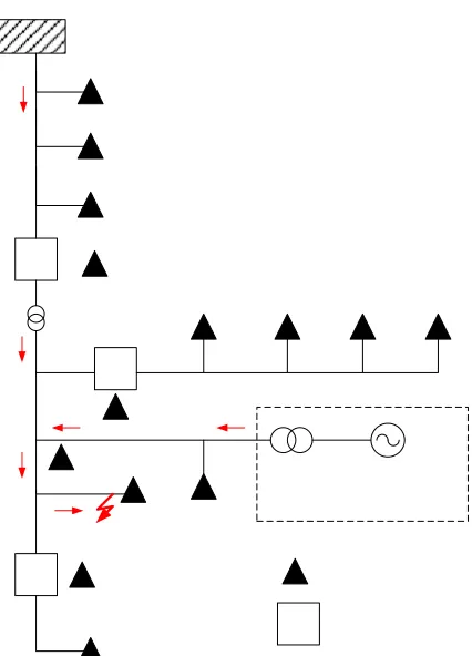
shown in Figure 2. The scheme under investigation is a
part of Thailand’s electricity distribution system. It can be seen that there are 14 nodes from substation while synchronous machine (biomass) is distributed generation that are connected at node 11. The recloser is installed at node 4, node 5, and node 13.
From simulation, the current of the load transformer which is installed at each node take into account the val-ue of the minimum and maximum current of protection device in power system with the correlation between the
magnitude of current in each nodes as shown in Figures
3 and 4, respectively.
4. Coordination between Recloser and Drop
out Fuse Cut out in Distribution System
[image:2.595.319.532.77.373.2]The objective of this paper is to study the coordination between recloser at node 4 and drop out fuse at node 12
[image:2.595.311.531.419.510.2]Figure 1. Equivalent circuit for short circuit current calcu-lation.
Figure 2. A simple radial system with DG connected at node 11.
1 2 3 4 5 6 7 8 9 10 11 12 13 14 0
50 100 150 200 250
Node
Load cu
rr
ent
(
A
)
[image:2.595.310.540.551.639.2]Load currnt phase A Load currnt phase A Load currnt phase A
Figure 3. Example of simulated load current for each node in case of no DG in distribution system.
1 2 3 4 5 6 7 8 9 10 11 12 13 14
50 100 150 200 250
Node
C
u
rre
n
t (A
)
Load Current Phase A Load Current Phase B Load Current Phase C
Figure 4. Example of simulated load current for each node in case of 8MW DG connected to the distribution system.
when DG is installed in distribution system. The case of
no DG which is shown in Figure 3, it is seen that, the
[image:2.595.69.279.595.708.2]configure the recloser in this minimum, which is equal to 350 A. The current of unbalanced load is considered as 25% of the load transformer, which can be configured to perform with the ground with the value less than 88 A.
of the protective device at node 4 (350 A) as shown in
Table 1 and Figure 6.
1 2 3 4 5 6 7 8 9 10 11 12 13 14 500
1000 1500 2000 2500 3000 3500 4000 4500 5000
Node
Thr
ee phase shor
tci
rcui
t cur
rent
(
A
) Three phase shortcircuit current (A)
From Figure 5, it is seen that, when the three phase
fault occurring at the node 12, the short circuit current of recloser at node 4 can be read with 619 A. The function
of the protective device as shown in Figure 6, when the
three phase fault occurring at the node 12, the operating time of protective device at the node 4 is 0.298 second which faster than the operating time of drop out fuse at node 12 (0.404 second) because of the short circuit cur-rent in the node 12 (619 A) higher than the pickup setting
[image:3.595.77.517.267.720.2]Figure 5. Example of simulated three phase fault current signals for each node in case of without DG in distribution system.
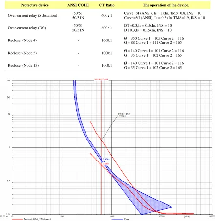
Table 1. The operation of protective devices in the electrical distribution system.
Protective device ANSI CODE CT Ratio The operation of the device.
50/51
50/51N 600 : 1
Curve=SI (ANSI), Is = 1xIn, TMS=0.8, INS = 10 Curve=VI (ANSI), Is = 0.3xIn, TMS=1.9, INS = 10 Over-current relay (Substation)
50/51
50/51N 600 : 1
DT =0.3,Is = 0.5xIn, INS = 10 DT 0.3,Is = 0.15xIn, INS = 10 Over-current relay (DG)
Ø = 350 Curve 1 = 105 Curve 2 = 116
Recloser (Node 4) - 1000:1
G = 88 Curve 1 = 111 Curve 2 = 165
- 1000:1 Ø = 140 Curve 1 = 101 Curve 2 = 116 G = 35 Curve 1 = 102 Curve 2 = 165 Recloser (Node 5)
[image:3.595.81.513.268.722.2]- 1000:1 Ø = 140 Curve 1 = 101 Curve 2 = 116 G = 35 Curve 1 = 102 Curve 2 = 165 Recloser (Node 13)
1 2 3 4 5 6 7 8 9 10 11 12 13 14 15 0
500 1000 1500 2000 2500 3000 3500 4000 4500 5000 5500 6000
node
T
hr
ee
pha
s
e
s
ho
rt
c
ir
c
u
it
c
ur
re
nt
(
A
)
[image:4.595.59.533.77.285.2]Short circuit current from substation Short circuit current from DG
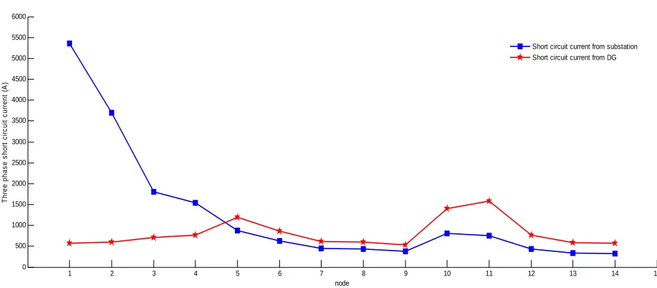
Figure 7. Example of three phase fault current signals for each node in case of 8 MW DG connected to the distribution system.
In case of 8 MW DG connected to the distribution system, it can be seen that, when three-phase fault occur-ring at node 12, the short circuit current have 2 source
that is injected from substation (I1) and DG (I2) as shown
in Figure 2 and Figure 7. For this case, when the three phase fault occurring at the node 12, the short circuit current of recloser at node 4 can be read with 441 A
which is the short circuit current from substation (I1) as
shown in Figure 2 and Figure 7 (blue line). It can be
seen that the short circuit current from substation (441 A) is lower than in case of no DG (619 A) because of DG is installed in distribution system so DG become the short
circuit current supply in system as shown in Figure 2
and Figure 7 (red line).
The purpose of the recloser’s installation is to clear temporarily fault from the distribution system. Generally, the recloser must be operated with fast curve before melting of drop out fuse in distribution system. For this case, when node 12 is considered, it can be seen that the
short circuit current (I3) that flows through the drop out
fuse at node 12 is higher than the recloser at node 4 due
that the short circuit current (I3) is generated from the
combination of the substation (I1) and DG (I2) as shown
in Figure 2. This is due to the protective sequence of protective device in the distribution system, will be
mal-function. From Figure 8, when three-phase fault
occur-ring at node 12, the short circuit current of recloser at node 4 can be read with 441 A so that fast curve of re-closer will be open with operating time of 0.509 second, but the short circuit current of drop out fuse at node 12 can be read with 1203 A and, then cause it to melt with operating time of 0.103 second. As a result, in this case, the protection device of the node 4 will be operated slower than drop out fuse at node 12, so the maintenance will be delayed more than expected.
5. Conclusions
This paper proposed the effects of coordination protec-tive device when the distributed generation (DG) is con-nected to the distribution system. The coordination be-tween recloser and drop out fuse is investigated in this paper. In case of no DG, the short circuit current is only injected from substation but, when the 8 MW DG is connected to the distribution system, the short circuit current from substation is reduced compared to the dis-tribution system without DG connected. In addition,
when node 12 is considered, the short circuit current (I3)
that flows through the drop out fuse at node 12 is
gener-ated from the combination of the substation (I1) and DG
(I2) as shown in Figure 2. This problem may cause the
protective device coordination inconsistently such as the protection device of the node 4 will be operated slower than drop out fuse at node 12 so the maintenance will be delayed more than expected. The coordination setting of protective device should be properly operated coordina-tion to reduced duracoordina-tion time of maintenance.
6. Acknowledgements
The authors wish to gratefully acknowledge financial support for this research from the energy policy and planning office (EPPO), Ministry of Energy, Thailand. They would like also to thank for the DIgSILENT pre-sented in this paper which is supported by Provincial Electricity Authority (PEA).
REFERENCES
[1] Y. M. Atwa, and E. F. El-Saadany, “Probabilistic Ap-proach for Optimal Allocation of Wind-based Distributed Generation in Distribution Systems,” IET Renewable
doi:10.1049/iet-rpg.2009.0011
[2] F. S. Abu-Mouti, and M. E. El-Hawary, “Heuristic curve-fitted Technique for Distributed Generation Opti-mization in Radial Distribution Feeder Systems,” IET Generation, Transmission & Distribution, Vol. 5, No. 2, 2011, pp. 172-180.doi:10.1049/iet-gtd.2009.0739
[3] S. Y. Su, C. N. Lu, R. F. Chang and Guillermo Gutierrez-Alcaraz, “Distributed Generation Interconnec-tion Planning: A Wind Power Case Study,” IEEE
Trans-actions on Smart Grid, Vol. 2, No. 1, 2011, pp. 181-189.
doi:10.1109/TSG.2011.2105895
[4] X. Liu, P. Wang, and P. C. Loh, “A Hybid AC/DC Mi-crogrid and Its Coordination Control,” IEEE Transactions
on Smart Grid, Vol. 2, No. 2, 2011, pp. 278-286.
doi:10.1109/TSG.2011.2116162
[5] R. Ciric, H. Nouri, and V. Terzija, “Impact of Distribute Generators on Arcing Faults in Distribution Networks,” IET Generation, Transmission & Distribution, Vol. 5, No. 5, 2011, pp. 596-601.doi:10.1049/iet-gtd.2009.0681
[6] S. R. Samantaray, A. Samui, and B. Chitti Babu, “Time-frequency Transform-based Islanding Detection in Distributed Generation,” IET Renewable Power Genera-tion, Vol. 5, No. 6, 2011, pp. 431-438.
doi:10.1049/iet-rpg.2010.0166
[7] P. K. Ray, N. Kishor and S. R. Mohanty, “Islanding and Power Quality Disturbance Detection in Grid-Connected Hybrid Power System Using Wavelet and S-Transform,”
IEEE Transactions on Smart Grid, Vol. 3, No. 3, 2012,
pp. 1082-1094.
doi:10.1109/TSG.2012.2197642
[8] S. R. Samantaray, K. El-Arroudi, G. Joos and I. Kamwa, “A Fuzzy Rule-Based Approach for Islanding Detection in Distributed Generation,” IEEE Transactions on Power
Delivery, Vol. 25, No. 3, 2010, pp. 1427-1433.
doi:10.1109/TPWRD.2010.2042625
[9] H. G. Far, A. J. Rodolakis and Geza Joos, “Synchronous Distributed Generation Islanding Protection Using Intel-ligent Relays,” IEEE Transactions on Smart Grid, Vol. 3, No. 4, 2012, pp. 1695-1703.
doi:10.1109/TSG.2012.2208659
[10] Ankita Samui and S. R. Samantaray, “Wavelet Singular Entropy-Based Islanding Detection in Distributed Gen-eration,” IEEE Transactions on Power Delivery, Vol. 28, No. 1, 2013, pp. 411-418.
doi:10.1109/TPWRD.2012.2220987
[11] M. Padhee, P. K. Dash, K. R. Krishnanand and P. K. Rout, “A Fast Gauss-Newton Algorithm for Islanding Detection in Distributed Generation,” IEEE Transactions on Smart Grid, Vol. 3, No. 3, 2012, pp. 1181-1191.
doi:10.1109/TSG.2012.2199140
[12] A. Samui and S. R. Samantaray, “Assessment of
ROCPAD Relay for Islanding Detection in
Distrib-uted Generation,” IEEE Transactions on Smart
Grid, Vol. 2, No. 2, 2011, pp. 391-398.