DESIGN AND DEVELOPMENT OF AN EMBEDDED ACTIVE
SOLAR TRACKING AND MANAGEMENT SYSTEM BASED
SBC
1NASEER SABRI,2SAIFALLAH M. ABGENAH,3M. S. SALIM,4NOAMAN M. NOAMAN,
2HAMZA A. JUMA
1Computer Engineering Department, AlNahrain University, Iraq 2Engineering College, University of Tripoli, Libya
3Laser and OptoElectronic Engineering Department, AlNahrain University, Iraq 4Informatics Engineering Department, AMA International University Bahrain, Bahrain
Email: [email protected]
ABSTRACT
Solar energy is gaining a rapid notoriety as an important source of renewable energy. Per se, it is vital for those who aim towards maximizing the total gain of its energy to utilize a method that will insure maximum energy gain by tracking the sun's position during its daily cycle. This research targets the means of collecting the utmost solar energy distributed by the sun by implementing an embedded tracking mechanism that will track the sun as it changes its position during its daily cycle. This embedded tracking system is developed based on an open source embedded single board computer (SBC) using an open source code that can be easily modified. The embedded tracking system is built on SBC type RaspberryPi as the main data collection and decision making unit for the system. This microcontroller is a part of an SBC developer's board that has a number of GPIOs to connect different peripherals to be used in the tracking system and controlled by the microcontroller. These peripherals consist of four LDR sensors to be used for sensing the sun's position by reading the light intake and sending the readings to the microcontroller to be processed, the LDR with the most light intensity readings will be the targeted position for the embedded tracking system to move the solar panel towards using two servo motors which will also be connected to the SBC via the GPIO pins, the two servo motors will have different tasks, one servo motor will be in charge of moving the solar panel vertically and the other servo will move the solar panel horizontally. The performance and characteristics of the solar tracker are experimentally analyzed to show the need and advantages of using this method of embedded tracking system. The results show that the designed embedded solar tracking system is efficiently tracking the sun and collecting more energy as compared to the static solar panels. In addition to the proposed embedded system has advantages over other system represented by real time tracking based on an active sun potion computing technique. The embedded solar tracking system offers cost effective and efficient solar tracking besides open source programming which allows for future enhancement and modification.
Keywords: Embedded Systems, Open Source Technology, Solar Tracker, Sensing, Solar Panels, Renewable Energy
1. INTRODUCTION
The Sun is an important element in this world we live in. Without Sun, nothing could exist because it’s the main source of energy for all living creatures. One other advantage that we gain from the Sun is solar energy. For millions of years, this energy has been used to produce heat, light and to grow plants. Modern day technologies are being developed to harness the utilization of such a clean energy application in order to address the global
the Sunlight hits the surface of the Solar Panel, but when the sun rotates as part of its daily cycle the Sunlight will not reach the surface of the Solar Panel, so the energy collected will reduce [1]. To solve this problem, a tracking system will be embedded into the Solar Panel. The basic function of this embedded tracking system will be to track the Sun during its daily cycle. To know the Sun's position a light dependent resistor sensor will be used to locate the Sun's position and this sensor will send data to a special program that will convert this data into coordinates. To move the Solar Panel, a Servo Motor
will be used; this motor will get the coordinates from the data sent from the sensor and move the Solar Panel to the desired location which in this case will be the position where the Sunlight is at its most intensity. The main processing unit for this embedded tracking system will be an SBC single board computer. This system is suitable to be used in homes or small factories that want to save their budget for a long term.
A. Embedded Systems
A system is a set of programs or connected hardware that has one or many tasks. The term Embedded System is commonly used by computer systems that are dedicated to a certain function or many functions within a larger system. The main advantages that an embedded system has over any general purpose computer is that it has lower power consumption, smaller size, portable and light weight, costs less and rugged operating ranges. Embedded systems nowadays exist everywhere like robotics, automobiles, airplanes, digital cameras, home appliances and even mobile phones [ 2].
There are many platforms that are considered to be embedded systems one of them is called the Single Board Computer (SBC). The SBC can carry out the tasks that a general purpose computer can do because it has a processor, storage unit, RAM and I/O ports that can be used to connect to other hardware devices and an operating system. SBC companies are widely spread and each company designs its own board based on the developers needs for example RaspberryPI, Technologic Systems, Beagle Bone and many more [3]. Beside, Microcontrollers are considered to be embedded systems which can also perform one or many tasks in a system.
B. Open Source Technologies
Open source technology is the development and production philosophy of making available the
developed source code of the software to end users and developers not only to use the code but they can also modify as per their own needs. The name Open Source is not only limited to software, but there can be open source hardware, where the end users can develop the hardware and modify it to suit their own needs [ 4].
2. EMBEDDED ACTIVE SOLAR TRACKING SYSTEM
Optimize utilizing of maximum solar energy through solar panels can be achieved by adopting; firstly, design an embedded system that can detect and compare the intensity of light. Secondly, design an embedded system that is able to move a Servo-Motor based on the intensity of light and show the voltage intake of Solar Panel, and lastly is by adopting an open source monitoring and tracking package that easiest to use system for other developers.
The proposed research is focused on designing and building the prototype of an embedded solar tracking system that would be a starting point to build the realistic solar tracking system. Therefore, this prototype will cover the scope as follows:
Move 90° vertically and 180° horizontally west and east.
Use two Servo-Motors for vertical and horizontal movements.
Use 4 Light Dependent Resistor [LDR] as sensors.
Read voltage intake of the solar panel using ADC and LCD.
Develop an open source tracking code.
3. RELATED WORK
Solar tracking is an important part of solar energy collection, because it maximizes the energy collected by following the Sun's location during the day as many researchers have found out by experiments various types of tracking methods. In this chapter the work done on solar tracking by various numbers of researchers is reviewed.
A. The Earth’s Movement around the Sun
celestial sphere around earth. The equatorial plane and celestial sphere intersect in polar axis and celestial equator. The motion of the earth around the Sun can be visualized by ostensible motion of the Sun in elliptic tilted at 23.458 degree w.r.t celestial equator. The angle between the lines that join the centers of the earth and the Sun and its prognosis on the equatorial plane is known as solar declination angle (δ). On March 20/21 and on September 22/23, this angle becomes zero. The rotation of the earth around polar axis is one revolution per day. This is represented by the rotation of the celestial sphere about the polar axis and prompt locus of Sun is labeled by hour angle v, the angle between the meridian of the site and meridian passing through Sun. At solar noon, the hour angle is zero and this rises in the east. For observers on the surface of the earth at a place with latitude φ, an expedient coordinate system is described by one vertical line at location that crosses the celestial sphere on two points, the nadir and the zenith, and subtends the angleφwith polar axis, Figure 1.
Figure 1: Graphic depiction of solar angles [5]
The big circle that is perpendicular to vertical axis is horizon. The latitude [φ] of a location can be defined as the angle made by radial line that joins the location to earth’s center with line’s projection on equatorial plane. The rotation axis of the earth crosses the surface of the earth at 900of North Pole
latitude and 900 of South Pole latitude. Any place
on earth’s surface can be described by intersection of latitude and a longitude angle. The α, solar altitude angle, thus can be described as the vertical angle between the direction of rays of the Sun passing through the point and the prognosis of the rays of the Sun on the horizontal plane as represented in Fig. 2. Alternatively, the altitude of the Sun can be defined in solar zenith angle i.e. θz
that is vertical angle between rays of the Sun and a perpendicular line to horizontal plane from the point
defined by θz= 900- α. γsi.e. solar azimuth angle is
defined as the horizontal angle from south to horizontal projection of rays of the Sun [ 6]. In order to calculate the solar positions and for defining relationship between stated parameters, many surveys are conducted. A FORTRAN program is used by Walraven to calculate the value of the parameter for Sun’s position. The parameters computed were for time, Sunset and Sunrise actual times, elevation, local azimuth, and declination and the computed Sun’s position was within 0.018 of accuracy [ 7].
B. Radiation on an Inclined and Tracking Surface
The data of solar radiations is generally found in global radiations form on horizontal surface and the position of PV panels is at an angle to horizontal plane. Consequently, the energy input to the PV system has to be calculated accordingly. There are three steps of this calculation. Firstly, for determining the beam and diffuse components of global irradiations on horizontal plane, the data for the site is used. This can be done by the use of extraterrestrial daily irradiationΒ0as reference and
by calculating the ratio
KT= G/Β0, called clearness index where G is daily
global irradiation on horizontal plane, and KTcan be
described as the mean reduction in solar radiation by atmosphere in a month at a specified. Secondly, diffuse radiation is found with the use of practical rule that the diffuse fraction D/G of global irradiation is general function of clearness index KT.
As B=G-D, this technique determines bean irradiation and diffuse on horizontal plane. Thirdly, apposite angles dependence of all factors is used in determining the beam irradiation and the diffuse on inclined surface. Allowing reflectivity of contiguous area, the albedo can be determined too. By adding above stated three elements, one can get total daily irradiation on inclined surface [8].
The Sun move on the sky in the day. The projection of collector area on plane perpendicular to the directions of radiations in fixed solar collectors is given by function cosine of angle of incidence, Figure 2.
The angle of incidence is denoted by θand the higher the value of θ, the lower the power is. In case of the usage of tracking collectors, theoretical calculation of extracted energy is done presuming maximum irradiation intensity at I=1100Wm-2
Figure 2: The θ, angle of incidence of solar radiation [8]
Taking the length of the day as t=12h=43,200s, the intensity of tracking collector is always oriented optimally facing the Sun as compared to the fixed collector perpendicularly oriented to the radiation direction at the time of noon only. The collector area is denoted by S0..
C. Energy Gain in Tracking Systems
One axis can be used for the implementation of solar tracking but if more accuracy is required then obviously two-axis Sun-tracking systems will be required. Two kind of Sun tacking systems are available for two-axis as; polar tracking and elevation/azimuth tracking. The solar tracker increases the accumulated energy and this is a device that preserves photo thermal panels or PV in optimal place that is perpendicular to radiations of the Sun in day light. Finster introduced the first completely mechanical tracker in 1962. After one year, an automatic-electronic-control mechanism was introduced by Saavedra that was used to orientate an “Eppley pyrheliometer” [8]. There is no need to place tracker direct towards Sun for efficiency. If the purpose is achieved by 100, 98.5
percent output of full tracking the output can be taken. While if it is cloudy, foggiest positions, 20 percent of the annual gain may be reduced. In a typically good area, the range of annual outcome would be 30 percent to 40 percent are normal. The range of outcome may vary between zeros to 100 percent in any day [ 9].
Agee et al. examined field applications and trends in market of technologies related to solar tracking, the allied costs and expenses, requirements for maintenance and ways to improve their efficiency. These researches include program-control systems, hydraulic systems and trackers based on sensors like single-axis or dual-axis types and trackers based on polar-axis. For installations of lower capacity, hydraulic systems found to be more suitable. Moreover, they asserted that the performance of polar-axis tracking systems is like two-axis type
systems but their cost is equal to single-axis tracking system [ 10].
There are few common characteristics of all types of tracking systems as follows [11][12][13][14]:
Two or one motors those are moving.
Structure based on one column.
Device of light sensing.
Auxiliary or independent supply of energy.
Moving or following light as per calendar.
Step-wise or continuous movement.
Whole year tracking or in exception of winter.
With or without tilt angle adjustment orientation.
4. EMBEDDED SYSTEM DESIGNING APPROACH
The Dual axis solar tracking system will track the Sun during the Sun's daily movement in a dual mode horizontally and vertically, the tracking process is done by using the SBC controller that will collect data from four Light dependent resistor sensors, data will be read from all four sensors but only the sensor with the highest light intensity readings will cause the Solar Panel to move towards the Sun's position using two servo motors, the first motor is for the vertical movement and the second motor is for the horizontal movement of the Solar Panel. An analog to digital convertor ADC0804 is used in system to show how much voltage we are gathering from the Sun with assist of attached LCD module. Figure 3 shows the overall system architecture.
A. Hardware Design
Figure 3: Overall Active Dual Axis Solar Tracking System Architecture
D. System Design
The system design consists of a an SBC board and four LDR sensors that are connected to the SBC board using the GPIO pins, each LDR sensor will be placed on the Solar Panel in a cross position, bottom left LDR sensor will be connected to PIN0 and to the GND PIN on the SBC board, bottom right LDR sensor will be connected to PIN1 and to the GND PIN on the SBC board, top left LDR sensor will be connected to PIN2 and to the GND PIN on the SBC board and the top right LDR sensor will be connected to PIN3 and to the GND PIN on the SBC board. Each of the LDR sensors will be connected to a 10k Ohm resistor before being connected to the GND PIN see Fig. 7 and 8 for system design and schematics.
The next step is to connect the two Servo motors throughout the signal conditioning and driving circuit to the SBC board, the first motor will move the Solar Panel horizontally and it is connected to PIN9 on the SBC board and the second motor will move the Solar Panel vertically and it is connected to PIN10 see Figure 4 for system design and schematics.
E. Software and System Operation
There are many types of tracking system algorithms that can be used to track the Sun, but since LDR sensors are used in this particular system this means that the system has an active tracking mechanism.
What is meant by active tracking is that the tracking systems use sensors to find the place where the Sun is at its most intense brightness and move the Solar Panel towards that position, if this position is changed it would immediately move the
Solar Panel towards the new position without waiting for a certain command or mathematical algorithms. The software part for the system is developed using a program that is written in C++ language.
Figure 4: Active Dual Axis Tracking System Schematic
The software of the system can be dived to three main functions. The first is the startup position or what is called the initial position. Since the system is an active tracking system the starting position of the Solar Panel is not an issue because as soon as the system is powered on, it will detect the Sun's position and immediately move the Solar Panel towards the Sun's position.
The second part is reading data from the four LDR sensors, the tracking system will be reading from all LDR sensors, but will only respond to the average LDR sensors either left top or left button compared to right LDR sensors with the highest light intensity reading, Figure 5.
Top left
(TL) Top Right(TR) Bottom Left
(BL) TL,BL TR,TL Top Left(TL)
Bottom
[image:5.612.321.514.157.320.2]Right (BR) BR,BL TR,BR Bottom Left(BL)
Figure 5: Light Detection Sequence
[image:5.612.337.528.527.588.2]The third part of the program is to move the two Servo motors based on the readings collected from the LDR sensors.
Figure 6: Cross Design used for LDR Sensors Placement on the Tracking System
[image:6.612.313.520.346.517.2]One servo motor is going to be responsible for the vertical movement of the system and the other Servo motor will move the system horizontally as shown in Figure 7.
Figure 7: Vertical and Horizontal Movement of the Tracking System
5. ANALYSIS AND EVALUATION CRITERIA
The validating process carried out for this design is to perform side by side the embedded active solar tracking design and passive system design under same sunspot and orientation. The accumulated percentage difference between those systems will be recorded for 10 hours with variant day environment such as clouds and clear sky. Cloudy sky has been categorized into fully and partially cloudy day. Indeed, system response time is computed.
6. RESULTS AND DISCUSSION
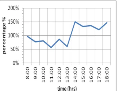
The results indicate that the tracking system has gained more voltage intake than the static system by showing an increase in voltage intake in the times where the sun had changed its position from the direction of the static system directed towards, as Figures 8,9 and 10 show. Moreover the dual axis tracking system has shown good performance by the time it takes to respond to the light's position
by having a response time of less than one second to move the solar panel towards the sun's position and this delay is due to the prototype's design not the actual code and tracking method see Figure 11. As known, the Sun has a daily movement cycle, causing the amount of Sunlight hitting the surface of the Solar Panel to change depending on the direction the Solar Panel is facing. This will cause the decrease of energy collected when the Solar Panel is not facing the Sun directly. To solve this problem this project a number of different tracking methods have been presented to increase the Solar Panel's performance of collecting Sunlight by tracking the Sun's position during the its daily cycle. Figure 8 shows that both the passive and designed the active tracker system behave with little bit variation during daylight morning hours for sunny days while before sunset the percentage difference increased for the active system since it has the ability to track the sunspot accordingly to gain maximum energy.
Figure 8: Percentage difference between the static and track systems for the sunny day
[image:6.612.150.235.347.421.2]Figure 9: Percentage difference between the static and track systems for the cloudy day
Contrarily, the passive system missed this during this time. While the percentage difference decreases when time moving towards evening day and hence both systems can not got sunspot even their solar panel face the sunspot. In general, during cloudy day the system behave shows confused results even though the active system yields the most energy gain.
[image:7.612.96.521.71.246.2]Partially cloudy day affects the percentage difference for both systems, as shown in Figure 10. The active system has shown its high gain of energy compared to passive system since afternoon time due to the sun movement that cause the sunlight to be partially invisible and thus the active system based on maximizing sensing energy provide a better gain of solar energy compared to passive and this increase all the time from afternoon till sunset.
Figure 10: Percentage difference between the static and track systems for the partially cloudy day
Figure 11: Testing time delay for the tracking system
Figure 11 presents the delay time in seconds of the designed active solar tracker system movement which indicate the performance of the tracker algorithm that guide the solar panel. Since the delay time for all position movements are within one second due to adaptive track movement except the point of sunrise where the system is initialized to track the sunspot in the early daylight. Most of the developed tracking systems require a high level of engineering and programming skills to maintain and develop if future developments are needed. Some other solar tracking systems developed using what is called passive tracking, which mainly depends on mathematical algorithms that calculate the Sun's movement depending on the location and geographical landscape the Sun tracker is placed, this method is not efficient because every time the Solar Panel is moved from its location new algorithms need to be calculated, and only people that are experts in the calculation can set the solar tracker again in its new location. Other tracking systems only track the Sun In one direction and known as single axis tracking systems. This method is not efficient because the Sun moves in more than one axis, which will make the amount of energy collected will be less than the solar energy that is out there to be collected.
This project presents an active dual axis solar tracking system that will track the Sun during the Sun's daily cycle. The term active means that the solar tracking system will be on standby when the there is no Sunlight or light source, as soon as the LDR sensors of the tracking system senses a light source it will move the Solar Panel towards the location of that light source, and if the direction of that light source changes the solar tracker will follow the light source to its new position.
[image:7.612.96.293.506.659.2]them show the advantage of using this tracking mechanism as the tests were done in three different weather conditions, sunny, partially cloudy and cloudy. All three tests gave the active dual axis solar tracking system an advantage over the Solar Panel that did not have a tracking system. As for the financial scale of the active dual axis solar tracking system, it has been found that the costs for building the system is very cheap compared to the other tracking systems out there, because the system uses an SBC board that is based on the SBC of Raspberry Pi as a main core of the system which is open source and cheap to buy SBC platform.
7. CONCLUSION
In conclusion the tracking systems are very useful for increasing the collection of solar energy not only in a single axis, but also in a dual axis mode and the method of active tracking is more efficient than passive tracking because it its portable and does not depend on a complex method of tracking. And thus, efficient energy accumulated is achieved beside simple and flexible open source single embedded system designed that can be adapted for different task situations as needed for system enhancements and optimization.
REFERENCES:
[1] Abdelkader, H. I., Saber, M., & Awed, A. S. [ n.a]. Efficiency Improvement of Sun Tracking Systems Controlled by FPGA. International Journal of Scientific & Engineering Research, 5[ 11], 364-379. [2] Ayoub, H. [ 2012]. Improving the energy
capture of solar collectors. Sustainable Engineering, Renewable Energy Systems & the environment, Sept, 156-160.
[3] Barsoum, N. [ 2011]. Fabrication of dual-axis solar tracking controller project. Intelligent Control and Automation, 2[ 02], 57.
[4] Bingöl, O., Altıntaş, A., & Öner, Y. [ 2011]. Microcontroller based solar-tracking system and its implementation. Pamukkale University Journal of Engineering Sciences, 12[ 2], 343-348.
[5] Clifford, M. J., & Eastwood, D. [ 2004]. Design of a novel passive solar tracker.Solar Energy, 77[ 3], 269-280.
[6] Crowston, K., & Howison, J. [ 2005]. The social structure of free and open source software development. First Monday, 10[
2].http://firstmonday.org/ojs/index.php/fm/art icle/view/1207/1127
[7] Deb, G., & Roy, A. B. [ 2012]. Use of solar tracking system for extracting solar energy. International Journal of Computer and Electrical Engineering, 4[ 1], 42-46.
[8] DeMicheli, G., & Sami, M. [ Eds.]. [ 2013]. Hardware/software Co-design [ Vol. 310]. Springer Science & Business Media. [9] Eseosa, O., & Roland, U [ 2013]. Design and
Simulation of Solar Monitoring Tracking System. IOSR Journal of Electrical and Electronics Engineering [ IOSR-JEEE], 4 [ 5], 35-39.
[10] Ferdaus, R. A., Mohammed, M. A., Rahman, S., Salehin, S., & Mannan, M. A. [ 2014]. Energy Efficient Hybrid Dual Axis Solar Tracking System. Journal of Renewable Energy,1-12.
[11] Khan, M. T. A., Tanzil, S. S., Rahman, R., & Alam, S. S. [ 2010, December]. Design and construction of an automatic solar tracking system. In Electrical and Computer Engineering [ ICECE], 2010 International Conference on [ pp. 326-329]. IEEE.
[12] Khlaichom, P., & Sonthipermpoon, K. [ 2007]. Optimization of solar tracking system based on genetic algorithms. In E-NETT 3nd Conference.
[13] Krishna, B. [ 2013]. Tracking of Sun for Solar Panels and Real Time Monitoring Using LabVIEW. Journal of Automation and Control Engineering Vol, 1[ 4].
![Figure 1: Graphic depiction of solar angles [5]](https://thumb-us.123doks.com/thumbv2/123dok_us/8907938.957732/3.612.96.293.374.507/figure-graphic-depiction-of-solar-angles.webp)
![Figure 2: The θ, angle of incidence of solar radiation [8]](https://thumb-us.123doks.com/thumbv2/123dok_us/8907938.957732/4.612.88.295.72.204/figure-th-angle-incidence-solar-radiation.webp)