c
⃝T ¨UB˙ITAK
doi:10.3906/elk-1502-229 h t t p : / / j o u r n a l s . t u b i t a k . g o v . t r / e l e k t r i k /
Research Article
Using magnetic field analysis to evaluate the suitability of a magnetic suspension
system for lightweight vehicles
Hazril Md. ISA1,∗, Noor Hafizah AMER2, Wan Nor Liza WAN MAHADI1, Rahizar RAMLI3
1Electromagnetic Radiation and Devices Research Group, Department of Electrical Engineering,
Faculty of Engineering, University of Malaya, Kuala Lumpur, Malaysia
2Department of Mechanical Engineering, Faculty of Engineering, National Defense University of Malaysia,
Kuala Lumpur, Malaysia
3Advanced Computational and Applied Mechanics Research Group, Department of Mechanical Engineering,
University of Malaya, Kuala Lumpur, Malaysia
Received: 26.02.2015 • Accepted/Published Online: 24.06.2015 • Final Version: 20.06.2016
Abstract:A suspension system in a vehicle acts as an isolator that isolates vibrations between the wheel tires and the vehicle body due to road irregularities. Additionally, a suspension system serves as a vehicle stabilizer that stabilizes the vehicle body during unusual driving patterns such as cornering, braking, or accelerating. A controllable suspension system has received significant attention in the automotive world in previous years since it can perform both of the aforementioned tasks without the presence of fluid damper. The study presented in this paper focuses on using magnetic flux density analysis to evaluate a number of parameters of an electromagnetic suspension system (EMS), so that it is suitable for usage in middle-sized passenger vehicles. The proposed EMS utilizes tubular linear actuator with a NdFeB permanent magnet. A number of dimensions of the EMS have been varied to observe their respective effect on force output and magnetic flux density. The purpose of this process was to determine what size of EMS will produce the same force as a standard suspension system, which has a maximum of 2000 N and an average of 800 N, according to quarter vehicle simulation that worked in parallel with this study.
Key words: Electromagnetic suspension, neodymium iron boron, damper, linear actuator
1. Introduction
In general, a suspension system in a vehicle serves as a shock absorber. Its purpose is to absorb vibrations
that result from road irregularities and prevent them from reaching the passenger. It also serves as a stabilizer to ensure that the wheel tire is in contact with the road surface at all times, thus increasing vehicle stability
during cornering, braking, or accelerating, boosting passenger safety and comfort during travel. The system also prevents damage to parts of the vehicle caused by excessive road vibration.
The difference between an electromagnetic suspension system (EMS) and any other type of suspension
system is that it operates using the magnetic field concept. An EMS uses the magnetic field concept to lift or levitate the vehicle body whenever it is supplied by an external power source. The concept of the EMS is
based on the interaction of two charged bodies, in which they will repel or attract each other depending on their polarity and magnitude of charge. Based on this concept, the EMS damping force can be controlled by varying
external power supply according to road conditions and driving pattern. An EMS can work without externally
changing its field strength (passively), and it can also act as a generator by generating electrical energy that
results from continuous linear movement between the magnetic field and current coils. The generated energy is then either kept in a storage system or fed back into the system.
2. Literature review
Recently, a suspension system that uses hydraulic damper has been widely used in all types of vehicles, since
its accessories are affordable and available on the market. However, hydraulic damper does not satisfy both
functions of suspension systems (comfort and stability) at the same time, due to its passive feature, in which
it can only temporarily store or dissipate energy. Since the suspension parameters are fixed, the stiffness and damping ratios are chosen on the basis of a compromise on specific road conditions in which the vehicle typically
operates [1].
Nowadays, cars tend to become smaller (SMART cars), incorporate a higher center of gravity (sports
utility vehicles), and have a reduced footprint [2], thus increasing the demand for controllable (active) suspension
systems. Active suspension supports the vehicle body and isolates passengers from road disturbances using
controlled force-generating components [3]. Active vibration control has been used to suppress vibration because
of its high damping capability [4]. Recently, various types of active suspension systems have been designed to
meet the aforementioned criteria including the linear actuator [5].().., ball screw–direct current (DC) motor
combination [6], and controllable damper [7].
The design proposed in this study will use an electromagnetic concept in a suspension system, in which
a tubular linear actuator (TLA) and neodymium-iron-boron (NdFeB) permanent magnet will be used as main
force-generating components. The TLA’s thrust force can be controlled by a control system mechanism subjected
to road conditions, and the dynamic response of the vehicle body and the wheels. It is combined with a spring to support the vehicle weight, thus producing an active suspension system.
This study focuses on the design and evaluation of an electromagnetic suspension system using a NdFeB
permanent magnet that meets the aforementioned criteria. A cylindrical NdFeB permanent magnet will be used in this design, as it contributes to a higher damping force for the suspension system.
2.1. EMS parameter evaluation
There are various parameters that have a significant effect on EMS performance. Besides force output, other
parameters associated with an EMS are air-gap, EMS radius/diameter, permanent magnet diameter, and pole
pitch. The important structure parameters that have a significant effect on EMS performance are air-gap and
copper thickness, in which, when air-gap thickness is decreased, the EMS force is increased [8].
Bianchi et al. [9] did some evaluations on the pole number to determine the possible EMS output. They
also evaluated the number of conductor turns in a coil that are suitable with EMS specifications. As a result, the number of turns is conflicting with the amount of current, coil resistance, and inductance. Wang and
Howe [10] studied the effect of magnetic field density ratio on EMS force/volume ratio. They showed that the
force/volume ratio reaches a maximum value at a certain point of the magnetic field density ratio. The pole
number in an EMS has been proven to have a significant effect on EMS performance via analytical analysis.
Observation of issues is pertinent to the design of TLAs for EMS application. Some issues are the thermal
and dimensional limitations [11]. The effect of normalized permanent magnet height on the average EMS force
[12]. Lee et al. [13] proposed a novel way of enhancing the magnetic force of the linear actuator by manipulating
the air-gap magnetic field distribution, using a periodic-ladder structure with designed electrical conductivity.
Kang et al. [14] used an existing TLA as a benchmark to design a fault-tolerant motor for EMS application.
They stated that force ripple has a significant effect on the performance of the EMS.
3. EMS structure
A TLA was used as a primary design of the EMS. This is because the TLA is volumetrically similar with tubular
[image:3.612.157.463.245.412.2]damper, which enables easy installation under the vehicle body. A NdFeB permanent magnet was used as the magnetic flux exciter. Figure 1 shows the EMS model proposed in this study.
Figure 1. Transparent view of EMS inside suspension tube.
As shown in Figure 1, the sets of coils are separated by iron teeth. The EMS is fed with current that flows through coils, which generate a magnetic field around it. Force is generated when magnetic fields from
both permanent magnets and current-carrying coils are interacting.
The boxed area in Figure 1 shows the active area view of the EMS where the magnetic fields interaction occurs. Thus, the magnetic flux distribution will be mainly focused in this area. The extra pole, or coils, outside
the active area will be specified based on maximum oscillation of the EMS during operation.
In cylindrical coordinates, Bianchi et al. [9] solved the equation using modified Bessel functions. If the
loop conductor with N turns is linked with another loop conductor, forming a set of loops (a phase), the total
electromagnetic force amplitude acting on that set of conductor loops at any axial position z is:
Fph=KtIsin (mnz) (1)
where Kt is an actuator constant.
Kt=−
2πKdpnNph (Ro−Ri)
∫ Ro
Ri
r[anBI1(mnr) +bnBK1(mnr)]dr
Kdpn is the winding factor and is the product of pitch factor and distribution factor, Kdpn=KpnKdn. The
dimension Nph is the number of conductor turns per unit phase and is the multiplication product of the number
inner radius of the coil, respectively. The function [anBI1(mnr) +bnBK1(mnr)] is the magnetic flux density
inside the air-gap area. The term mn is the spatial wave number, in which mn=π/polepitch .
4. Methodology
In this paper, the magnetic flux and EMS force will be evaluated to determine the suitable dimensions that can produce a specified force. The evaluation process is done entirely in a virtual environment using Ansoft Maxwell
2D that provides finite element analysis. EMS dimensions are varied to evaluate the resulting force output and magnetic field density inside it. EMS dimensions that produce an output force nearest to the required force will
be chosen as the primary design. This process is important because it allows us to determine the exact size of the EMS that produces the required force. A validated theoretical model in Section 3 is used in this process.
There are three main dimensions that are being varied: EMS radius, EMS length, and air-gap thickness, since
they have a significant effect on the output force and also the magnetic field density inside it [8]. The initial
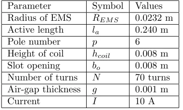
dimensions for evaluation are shown in Table 1. For EMS radius, the range of evaluation starts from a base value
of 0.0232 m to a maximum value of 0.0832 m. For EMS axial active length, the range of evaluation starts from a minimum length of 0.24 m to a maximum length of 0.40 m. The maximum values for EMS radius and active
length have been set that way because they are the most realistic dimensions that can fit into the suspension working space. For air-gap length, the evaluation range starts from 0.001 m and ends with 0.004 m. The result
[image:4.612.211.400.416.530.2]of this process is that the EMS is able to produce a maximum output force of 2000 N and an average force of 800 N to maintain vehicle stability.
Table 1. EMS dimensions prior to evaluation.
Parameter Symbol Values
Radius of EMS REM S 0.0232 m
Active length la 0.240 m
Pole number p 6
Height of coil hcoil 0.008 m
Slot opening bo 0.008 m
Number of turns N 70 turns
Air-gap thickness g 0.001 m
Current I 10 A
5. Findings and discussion
At first, the radius of the EMS was varied from 0.032 m to 0.082 m to examine its effect on the force output. Figure 2 shows the magnetic flux density in the air-gap region against coil position when the radius of EMS
(REM S) is increased.
The results in Figures 2 and 3 show that the EMS force increases when the radius is increased. An
EMS with a radius of 0.0832 m exerts as much as 1043.5 N on the vehicle body compared to smaller EMS radius, which exerts a smaller force. This is because when the radius of the EMS increases, the thickness of the
permanent magnet increases as well, causing an increment in the magnetomotive force. With air-gap reluctance constant, magnetic flux across the air-gap increases with the increase in magnetic flux density inside the air-gap
–1500 –1000 –500 0 500 1000 1500
–0.08 –0.06 –0.04 –0.02 0 0.02 0.04 0.06 0.08 Position. m Force. N Rems=0.0232 Rems=0.0432 Rems=0.0632 Rems=0.0832 –0.8 –0.6 –0.4 –0.2 0 0.2 0.4 0.6 0.8
–0.08 –0.06 –0.04 –0.02 0 0.02 0.04 0.06 0.08 Position. m Magnetic Flux Density. T Rems=0.02
[image:5.612.73.542.91.242.2]32 Rems=0.04 32 Rems=0.06 32
Figure 2. Effect of EMS radius on force. Figure 3. Effect of EMS radius on magnetic flux density.
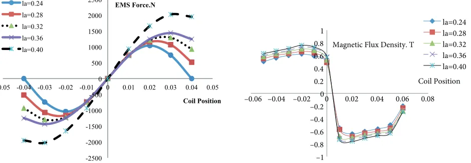
Figure 4 shows the variation of EMS force with coil position when its length is varied.
Figure 4 suggests that the peak force is 2050 N when the length of the EMS is 0.40 m. It is also observed that when EMS length is increased, the force becomes less sinusoidal. This is because when the length of the
EMS increases, the frequency of force decreases with constant pole pitch, making the force in the EMS with longer length lag behind the force in the EMS with shorter length. Figure 4 shows the corresponding magnetic
flux density against coil position.
Based on Figure 5, the magnetic flux density inside the EMS with a length of 0.40 m is 0.78 T, which is
the highest value compared to other EMS lengths. This is because when the length of the EMS increases, the length of the permanent magnet and the width of the teeth also increase, in turn causing the magnetomotive
force to increase. With constant air-gap thickness, the number of magnetic fluxes across it increases. Thus, from the results above, the length of the EMS was chosen as 0.40 m.
-2500 -2000 -1500 -1000 -500 0 500 1000 1500 2000 2500
-0.05 -0.04 -0.03 -0.02 -0.01 0 0.01 0.02 0.03 0.04 0.05
Coil Position EMS Force.N la=0.24 la=0.28 la=0.32 la=0.36 la=0.40 –1 –0.8 –0.6 –0.4 –0.2 0 0.2 0.4 0.6 0.8 1
–0.06 –0.04 –0.02 0 0.02 0.04 0.06 0.08 Coil Position Magnetic Flux Density. T
[image:5.612.72.542.451.614.2]la=0.24 la=0.28 la=0.32 la=0.36 la=0.40
Figure 4. Effect of EMS length on force. Figure 5. Effect of EMS length on magnetic flux density.
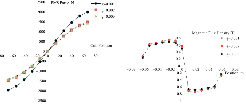
The effect of air-gap thickness on EMS force and magnetic flux density has been examined. Figure 6 shows the variations of EMS force against coil position when the thickness of the air-gap is varied.
The results in Figure 6 show that the EMS force is slightly decreased when the air-gap thickness is
increased. This is because when the air-gap thickness increases, the thickness of the permanent magnet decreases,
the air-gap to increase, thus reducing the amount of magnetic flux across it. Figure 7 shows the magnetic field density of the EMS with different air-gap thicknesses.
–2500 –2000 –1500 –1000 –500 0 500 1000 1500 2000 2500
–80 –60 –40 –20 0 20 40 60 80 Coil Position EMS Force. N g=0.001
g=0.002 g=0.003 –1 –0.8 –0.6 –0.4 –0.2 0 0.2 0.4 0.6 0.8 1
–0.08 –0.06 –0.04 –0.02 0 0.02 0.04 0.06 0.08 Position. m Magnetic Flux Density. T
g=0.001
g=0.002
[image:6.612.72.543.132.332.2]g=0.003
Figure 6. Effect of air-gap thickness on EMS force. Figure 7. (a) Output voltage of CSPWM modulation; (b) Harmonic spectrum of output voltage.
Based on the results above, the air-gap thickness for the EMS is chosen as 0.001 m. Although a value
lower than 0.001 m can be implemented, it is limited by manufacturing tolerance. Figure 7 shows the magnetic field distribution in the EMS with different air-gaps.
In Figure 8, the air-gap size has been varied between three different values, namely 0.003 m (Figure
8a), 0.002 m (Figure 8b), and 0.001 m (Figure 8c). It has been observed that as the air-gap gets smaller, the
magnitude of stray flux increases. In Figure 8a, the magnitude of stray flux measured at the air-gap is 0.004 T; in Figure 8b, the magnitude is 0.008 T; and in Figure 8c, the magnitude is 0.01 T. However, the magnitude range
is considered acceptable and does not impact the performance of EMS operation [10]. The air-gap thickness can
be decreased further, but 1 mm is considered small enough for manufacturing tolerance [11]. Thus, the air-gap
[image:6.612.172.440.568.659.2]is chosen to be as small as possible, which is 0.001 m. Table 2 shows the EMS parameters after the evaluation process.
Table 2. Angles of interval up to 90◦.
Parameter Symbol Values
Radius of EMS REM S 0.0832 m
Active length la 0.380 m
Pole number p 6
Number of conductor turns per coil Ncoil 70 turns
Air-gap thickness g 0.001 m
Maximum current I 10 A
Based on the evaluation process, it is found that the radius of the EMS should be 0.0832 m, and its
length should be 0.380 m in order for it to produce a maximum force of 2000 N with a maximum current of 10
(a)
[image:7.612.93.519.85.665.2](b)
(c)
Figure 8. Continued.
6. Conclusions
For a typical lightweight vehicle, each suspension needs to exert a maximum force of 2000 N and an average force of 800 N on the vehicle body to maintain its stability during driving. These data have been obtained
through quarter vehicle simulation that was done parallel with this study. This paper describes that we have successfully observed the possibility of replacing the hydraulic damper with an EMS, which can exert the same
force as a hydraulic damper. A virtual EMS has been designed in Ansoft Maxwell 2D, its dimensions were varied, and its force output for each value was observed. It was found that the volume of the EMS needs to
be at least 0.0082 m3 for it to produce the same damping force as the hydraulics on the vehicle body. The
dimensions of the EMS were 5% larger than a typical model and it needs current excitation to operate. Finally, simulation on magnetic field distribution revealed that EMS performance can be affected by the size of the
air-gap between the permanent magnets and the iron core. Thus, it has been minimized to 0.001 m to mitigate the problem. The stray flux present as a result of air-gap minimization was deemed not significant according
to previous literature. Ultimately, this model can be an alternative to the hydraulic system. It operates in the absence of fluid, the force is controllable, and it also has the potential to regenerate electrical energy.
References
[1] Mirzaei S, Saghaiannejad V, Tahani V, Moallem, M. Electromagnetic shock absorber. In: Electric Machines and
Drives Conference; 17–20 June 2001; Cambridge, MA, USA. p. 760.
[3] Lee S, Kim W. Active suspension control with direct-drive tubular linear brushless permanent-magnet motor. IEEE T Contr Syst T 2010; 18: 859-870.
[4] Okada Y, Harada H. Regenerative control of active vibration damper and suspension systems. In: Conference on
Decision and Control; 13 December 1996; Kobe, Japan. pp. 4715-4720.
[5] Zhaoxiang D, Fei L. Electromagnetic active vehicle suspension system. In: Third International Conference on
Measuring Technology and Mechatronics Automation; 6–7 January 2011; Shangshai, China. pp. 393-397.
[6] Kawamoto Y, Suda Y, Inoue H, Kondo T. Modeling of electromagnetic damper for automobile suspension. Journal
of System Design and Dynamics 2010; 1: 524-535.
[7] Yao GZ, Yap FF, Chen G, Li WH, Yeo SH. MR damper and its application for semi-active control of vehicle suspension system. Mechatronics 2002; 2: 963-973.
[8] Gysen BLJ, Janssen JLG, Paulides JJH, Lomonova EA. Design aspects of an active electromagnetic suspension
system for automotive applications. IEEE T Ind Appl 2009; 45: 1589-1597.
[9] Bianchi N, Bolognani S, Corte DD, Tonel F. Tubular linear permanent magnet motors: an overall comparison.
IEEE T Ind Appl 2003; 39: 466-475.
[10] Wang J, Howe D. Tubular modular permanent-magnet machines equipped with quasi-Halbach magnetized magnets
part I: magnetic field distribution, EMF and thrust force. IEEE T Magn 2005; 41: 2470-2478.
[11] Wang J, David H. A general framework for the analysis and design of tubular linear permanent magnet machines.
IEEE T Magn 2011; 35: 1986-2000.
[12] Ngoc ND, Zhaoxiang D, Youqiang C. Direct current linear actuator using in the active suspension system of automobile. In: International Conference on Electric Information and Control Engineering; 15–17 April 2011; Wuhan, China.
[13] Lee J, Dede EM, Banerjee D, Iizuka H. Magnetic force enhancement in a linear actuator by air-gap magnetic field
distribution optimization and design. Finite Elem Anal Des 2012; 58: 44-52.
[14] Kang M, Ji J, Liu G, Zhao W. A new tubular fault-tolerant permanent-magnet motor for active vehicle suspension.