5
IX
September 2017
Implementation of Efficient Binary To Gray Code
Converter Using Quantum Dot Cellular Automata
P.Chaithanya1, B.Ramesh2, V.Srujana3, V.Vikram4
1, 3, 4
Assistant Professor, 2 Associate Professor, KITS, Singapuram
Abstract: Quantum dot cellular automata is one of the emerging nano technology in IC industry because it can overcome the limitations of CMOS technology like power dissipation ,leakage current etc.QCA technology is used extensively in digital circuits and systems. In conventional computers information is transferred from one place to another by means of electrical current, in QCA by propagating the polarization state the information is transferred.QCA circuits are operated at terahertz frequency so switching time and power dissipation of the circuit reduces. In this paper QCA based high speed code converters are implemented with reduced no of cells and area.
Keywords: Quantum Dot Cellular Automatta cell,QCA Clock,MajorityVoter,Code converter
I. INTRODUCTION
According to International Semiconductor Road map (ISRM) Quantum-dot cellular automata (QCA) has one of the emerging technology .CMOS technology facing a lot of problems in nano scale era.QCA is the best alternative to CMOS technology.
A. QCA Cell
Basic element of QCA is QCA cell shown in fig1.a. It consists of two electrons with four quantum dots positioned at the vertices of a squared cell. The logic functions are performed by Coulomb interactions. The Coulomb interactions and the quantum mechanical tunneling is done between the dots due to the interaction of the electrons in the QCA cell, but they cannot leave the cell[1].If two mobile electrons are placed diagonally in the cell. The polarity of the cell is shown in fig.1.b&cThe basic blocks of QCA is a QCA wire, QCA inverter and QCA majority gate.
Fig.1.a)QCA cell b) pollarity’1’ c) polarity’0’
B. QCA Wire
QCA wire simply acts like a binary wire. In QCA wire, the binary signal propagates from input to output because of the electrostatic interactions between cells.
The propagation in a 90˚ QCA wire is shown in Fig. 2. Other than the 90˚ QCA wire, a 45˚ QCA wire can also be used. In this case, the propagation of the binary signal alternates between the two polarizations [2,4].
Fig.2.QCA wire(900)
Fig.3.QCA wire(450)
C. Majority Gate
Fig.4.Majority Gate
By fixing the polarization of majority gate input to 0 (P=-1)it acts like an AND gate.If the polarization of majority gate input fixed to 1(p=1)it acts like an OR gate.
Fig.5.2 input AND and 2 input OR gate
D. QCA Inverter
Compared to conventional NOT gate or Inverter QCA inverter is simple. The electrostatic interaction between the dots is inverted, because the quantum-dots corresponding to different polarizations are misaligned between the cells [5].
Fig.6.a)QCA Inverter b)Robust inverter
QCA technology is depends on charge transfer rather than electron flow.In QCA synchronization of information is done by clocking mechanism. QCA take advantage of quantum-mechanical effects to significantly increase the speed ,reduce the size and power of digital circuits.
E. QCA Clocking
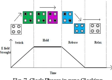
During the Switch phase, the initial state of the QCA cell is unpolarized and the interdot barrier are slowly raised which pushes the electrons into the corner dots, so the cell become polarized under the influence of its neighbors. In this state actual computation is performed. In the hold phase the barriers are high and cell state is fixed and retains its polarity and acts as input to the neighboring cells. In the relax phase, the electrons are pulled into the middle dots, so the cell state becomes “null”. Finally in the release phase, barriers are lowered and the electrons are pulled into the middle dots so the cell state becomes unpolarized. Here switching is adiabatic, i.e. the system remains very close to the energy ground state during transition, and the stationary state of each cell can be obtained by solving the time-independent Schrodinger equation. Clocking zones of a QCA circuit system are arranged in cyclic fashion, so that zones in the Hold phase are followed by zones in the Switch, Release and Relax phases[17].
Fig .7. Clock Phases in zone Clocking
Fig.8.Clock coding of clocks in zone clocking
This clocking method makes the design of QCA different from CMOS circuits. The Fig. 6 shows the four available clock signals. Each signal is phase shifted by 90˚ degrees. When the clock signal is low the cells are latched. When the clock signal is high the cells are relaxed and have no polarization. In between, the cells are either latching or relaxing when the clock is decreasing or increasing respectively
F. Crossover
The collection of two intersecting QCA wires is known as a crossover .There are several approaches to design a cross over. Most used approaches are Multi layer and Coplanar approach.
1) Multi-layer approach: This QX architecture uses two substrate layers to avoid interference [6].
2) Coplanar approach: One-layer QX is possible via 45- degree rotation of all QCA cells of one of the wires. This structure is unfortunately not robust enough [7] [8].
G. QCA Fabrication technologies
QCA cells are realized with different fabrication technologies [9]; namely Metal Island [10], Semiconductor [11], Molecular [12], and Magnetic [13]. Metal Island and semiconductor products require very low working temperature, while those of others work in room temperature. The Molecular alternative provides very small QCA cells (contrary to Magnet) ultra high working frequency in Tera hertz. However, there are some shortcomings such as difficulty of realization of rotated cells [14].
H. Code converters
1) Binarycode: A binary code represents text, computer processor instructions.Binary code is the simplest form of computer code or programming data. It is represented entirely by a binary system of digits consisting of a string of consecutive zeros and ones. 2) Graycode: The logic circuit which converts binary to gray code is called binary to gray code converter. Gray code is a non
I. Binary to Gray code converter
The M.S.B. of the gray code will be exactly equal to the first bit of the given binary number. Now the second bit of the code will be exclusive-or of the first and second bit of the given binary number, i.e if both the bits are same the result will be 0 and if they are different the result will be 1.The third bit of gray code will be equal to the exclusive-or of the second and third bit of the given binary number. Thus the Binary to gray code conversion goes on.
[image:5.612.230.382.211.357.2]II. QCAIMPLEMENTATIONOFBINARYTOGRAYCODECONVERTER
Figure 8-10 shows the simplified block diagrams of 2-bit
binary to gray code and 3-bit binary to gray code and 4-bit binary to gray code converter using Majority voter[16].
A. 2-bit binary to gray code converter
[image:5.612.213.396.391.721.2]Fig .9. Block diagram of 2-bit binary to gray code converter
Table 1.Truth Table Deci
mal
Binary B0B1
Gray G0G1 0 0 0 0 0 1 0 1 0 1 2 1 0 1 1 3 1 1 1 0
B. 3-bit binary to Gray code converter
Table2.Truth Table Decimal Binary
B0B1B2
Gray G0G1G2
0 000 000
1 001 001
2 010 011
3 011 010
4 100 110
5 101 111
6 110 101
7 111 100
C. 4-bit binary to gray code converter
Fig.11.4-bit Binary to Gray code converter
Table3.Truth Table Decimal Binary
III. SIMULATIONANDRESULTS
The code converter circuits are designed using QCA Designer 2.0.3. The simulated QCA circuit layout of 2-bit binary to gray, 3-bit binary to gray and 4-bit binary to gray code converter are shown in figure 11to 15 respectively.
The logical equation of two bit binary to gray code converter is G1 = B1 and G0 = B1⊕B0.
Fig.12.Layout of 2bit bit Binary to Gray code converter
Fig.13.Simulated output of 2bit Binary to Gray code converter
From the simulated output of 2bit binary to gray code converter shown in figure12 , we observe that the binary inputs B1 and B2 are applied at clock0 we get the output G1 at clock0 and output G0 at clock2.
For three bit binary to gray code converter the logical equations are G0 = B0, G1 = B1⊕B0 and G2 = B2⊕B1.
Fig.15.Simulated output of 3bit Binary to Gray code converter
From the simulated output of 3bit Binary to Gray code converter shown in figure14 we observe that the binary inputs B0,B1 and B2 are applied at clock0 we get the output G0 at clock0 and output G1 and G2 at clock2.
The logical equations of four bit binary to gray code converter is G3 = B3, G2 = B3⊕B2, G1 = B2⊕B1 and G0 = B1⊕B0.
Fig.16.Layout of 4bit bit Binary to Gray code converter
From the simulated output of 4-bit Binary to Gray code converter shown in figure16 we observe that the binary inputs B0,B1 B2 and B3 are applied at clock0 we get the output G0 at clock0 and output G1 ,G2 and G3 at clock2.
Table4.Performance factors of Binary code Gray converter Binary to Gray
code converter
No of cells Area in µm2
2-bit[16] 44 0.06
2-bit proposed 41 0.04
3-bit[16] 86 0.11
3-bit proposed 73 0.07
4-bit [16] 127 0.13
4-bit proposed 105 0.09
IV. CONCLUSION
In this paper, an effective QCA based binary to gray converter has been presented in detail. The proposed designs are fit in the manner that they enclose less number of cells, clock phases and area. QCA technology is the best alternative of CMOS based technology.The simulation outcomes present that the proposed circuits execute well. These methods are conducive in quantum computing, digital signal processing (DSP), and nanotechnology.
REFERENCES
[1] A. O. Orlov, I. Amlani, G.H. Bernstein, C. S. Lent and G.L. Snider, “Realization of a functional cell for quantum-dot cellular automata”, Science, vol. 277, pp. 928-930, 1997.
[2] C. S. Lent, P. D. Tougaw, and W. Porod, “Bistable saturation in coupled quantum dots for quantum cellular automata”, Applied Physics Letters, vol. 62, iss. 7, pp. 714-716, February 15, 1993.
[3] P. D. Tougaw and C. S. Lent, “Logical devices implemented using quantum cellular automata”, Journal of Applied Physics, vol. 75, iss. 3, pp. 1818-1825, February 1, 1994.
[4] M. Crocker, M. Niemier, X. S. Hu, and M. Lieberman, “Molecular qca design with chemically reasonable constraints,” ACM Journal on Emerging Technologies in Computing Systems (JETC), vol. 4, no. 2, p. 9, 2008.
[5] T. J. Dysart, and P. M. Kogge. "Probabilistic analysis of a molecular quantum-dot cellular automata adder." Defect and Fault-Tolerance in
VLSI Systems, 2007. DFT'07. 22nd IEEE International Symposium on. IEEE, 2007, pp. 478-486.
[6] A.Gin,P.D.Tougaw,and Williams,”An alternative geometry for quantum -dot cellular automata,”Journal of applied physics,vol.85,no.12,pp.8281-8286,1999.
[7] K.Walus and G.A.Jullien,”Design tools for an emerging soc technology: uantumdotcellularautomata,”ProceedingsoftheIEEEvol.94,no.6,pp.1225-1244,2006.
[8] M. Crocker, M. Niemier, X. S. Hu, and M. Lieberman, “Molecular qca with chemically reasonable constraints,”ACM Journalon Emerging Technologies in Computing Systems (JETC), vol. 4, no. 2, p. 9, 2008
[9] Vacca, Marco. "Emerging Technologies-NanoMagnets Logic (NML)."PhD diss., Politecnico di Torino, 2013.
[10] Kummamuru, Ravi K., et al. "Operation of a quantum-dot cellular automata (QCA) shift register and analysis of errors." Electron Devices, IEEE Transactions o, Vol. 50, no. 9, pp. 1906-1913, 2003.
[11] Single, C., et al. "Towards quantum cellular automata operation in " Superlattices and Microstructures vol. 28, no. 5 pp. 429-434, 2000.
[12] Lu, Yuhui, Mo Liu, and Craig Lent. "Molecular quantum-dot cellular automata: From molecular structure to circuit dynamics." Journal of applied physics vol. 102, no. 3, p. 034311, 2007.
[13] Niemier, M. T., et al. "Nanomagnet logic: progress toward system-level integration." Journal of Physics: Condensed Matter, vol. 23, no. 49, p. 493202, 2011.
[14] Chaudhary, Amitabh, et al. "Fabricatable interconnect and molecular QCA circuits." IEEE Transactions on Computer-Aided Design of Integrated Circuits and Systems,vol. 26, no.11, pp. 1978-1991, 2007.
[15] J. Iqbal, F. A. Khanday*, N. A. Shah.” Efficient Quantum Dot Cellular Automata (QCA) Implementation of Code Converters”. International Journal of Communications in Information Science and Management Engineering, Oct. 2013, Vol. 3 Iss. 10, PP. 504-515
[16] Shifatul Islam, Mohammad Abdullah-al-shafi and Ali Newaz bahar “Implementation of Binary to Gray Code Converters in Quantum Dot Cellular Automata “Journal of Today’s Ideas – Tomorrow’s Technolo gies,Vol. 3, No. 2, December 2015 pp. 145–160
![Figure 8-10 shows the simplified block diagrams of 2-bit binary to gray code and 3-bit binary to gray code and 4-bit binary to gray code converter using Majority voter[16]](https://thumb-us.123doks.com/thumbv2/123dok_us/8306032.856101/5.612.230.382.211.357/figure-simplified-diagrams-binary-binary-binary-converter-majority.webp)
