5
X
October 2017
Kinematic Analysis and Prototype Development of
CVVl Mechanism for Throttle Free Load Control
in Si Engine
Megha A. Mohite1, Santosh B. Trimbake21, 2
Mechanical Department, College of Military Engineering, Pune
Abstract: An innovative solution for throttle free load control for SI engines is Continuous Variable Valve Actuation (CVVL) systems. Such systems provides more efficient, improve dynamic performance, fewer emissions by reducing fuel consumption and allows performing an optimized operations. CVVL mechanism with three elements consists of eccentric shaft fitted with a series of intermediate rocker arm, which in turn control the degree of valve lift.
This paper presents the kinematic analysis of novel CVVL mechanism with three elements , carried out in Ricardo VALDYN-Kinematics software for small capacity single cylinder motorcycle engine. It ensures a continuous valve lift between two extreme heights. Kinematic analysis of the mechanism includes valve lift, velocity, acceleration and contact stresses.
Based on kinematic analysis results CVVL mechanism prototype was developed and retrofitted on 200cc DOHC single cylinder motorcycle engine. The result in terms of valve lift variation at different operating conditions compared with the kinematic analysis results and found to be in good agreement under the given set of operating conditions.
Keywords: CVVL - Continuous Variable Valve Lift, Kinematic analysis, Valve lift, VALDYN-Kinematics
I. INTRODUCTION
The Conventional IC engines have mechanically-actuated valve motions, fixed with respect to the crankshaft position for all engine operating conditions. These valve motions (such as valve lift profile, event timing, and opening duration) are determined during the engine design stage by fixing the cam profile and its position. As such, the valve motions contain a number of engineering trade-offs involving engine performance, exhaust emissions, and fuel consumption over a full range of engine operating conditions. Until now, these technical compromises have been generally accepted within the industry because the performance, environmental, and efficiency requirements for IC engines can be and have been satisfied. However, increasing demands for improved fuel economy and stringent government regulations on exhaust emissions begin to motivate many researchers and engineers to explore alternative means in which the valve motions are no longer fixed to the crankshaft position. In this new approach, referred to as Variable Valve Actuation (VVA) engine technology, additional degrees of freedom allow the Valve events to be selectively optimized and controlled to provide a unique valve motion for each region of engine operating conditions to present the optimal engine performance, emissions, and fuel economy benefits at each particular operating region [1-3]. The design of an IC engine is a complex compromise between performance, fuel economy and emissions. These factors are interrelated and cannot be simultaneously optimized. Once the physical parameters such as displacement, cam profile and compression ratio are determined, a conventional engine has nearly fixed performance, fuel economy and emissions properties. By making an engine more efficient, one or more of these factors could be increased without significantly compromising the others [1-3]. Variable Valve Actuation (VVA) technology allows better engine performance by reducing fuel consumption and therefore low emissions, higher efficiency, highly precise responsiveness of the powertrain. The key parameter for SI engine combustion, and therefore efficiency, emissions and fuel consumption is the quantity and characteristics of the fresh air charge in the cylinders. In conventional SI engines, the throttle-based air control wastes about 10% of the input energy in pumping the air. Novel Continuously Variable valve lift mechanism is responsible for the best fuel economy, improvement in volumetric efficiency and increase peak torque and power [1-5]. The present work includes kinematic analysis and subsequent prototype development of Continuous Variable Valve Lift mechanism.
II. CONTINUOUSVARIABLEVALVELIFT
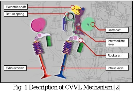
performance The CVVL mechanism mainly consists of the following components: electric motor, eccentric shaft, intermediate lever, roller rocker arm, and cam/camshaft. The motor turns the eccentric shaft which moves the intermediate lever back and forth. The intermediate lever has a roller in the middle which is in direct contact with the cam. The upper end of the lever is in contact with the eccentric shaft while its lower end is in contact with the roller rocker arm, which eventually activates the valve motion, as shown in Figure 1.
Fig. 1 Description of CVVL Mechanism [2]
In the case of no or low lift, the motor turns theeccentric shaft so that the contact surface between the intermediate lever and the roller rocker arm remains almost flat. In this case, the roller rocker arm moves only along the flat surface so that the rotation of camshaft produces no or very small valve lift as intended.
In the case of high lift, however, the motor turns the eccentric shaft so that the contact surface between the intermediate lever and the roller rocker arm becomes more round. The roller rocker arm then moves along the rounded surface so that the rotation of camshaft now results in a high lift of the intake valve. Based on this operating principle, the system can generate the intake valve lift profile.
III.NUMERICALMODELLINGOFCVVLWITHVALDYN-KINEMATICS
A. Valdyn kinematic basics [6]
The VALDYN Kinematic Solver is a program for the design and kinematic analysis of valvetrain systems. It uses a building block approach so that standard and unconventional valvetrains or partial valvetrains can be modelled. All the common valvetrain types can be analyzed such as linearly translating followers and swinging followers with or without a push rod and rocker system, as well as continuously varying valve lift (CVVL) systems. The program ca either be used to assess an existing cam design or can be used to generate a cam profile using the Ricardo ’Multipol’ technique. This is a spline type technique developed at Ricardo over period of several years specifically for quick and easy optimization of automotive and heavy duty engine valve profiles.
1) Workflow/Modes of VALDYN [6]: The VALDYN GUI contains three distinct Modes that align with the standard CAE system modelling and simulation process, from start to finish. The modes in VALDYN are :
a) Model Mode: Model building and input of object boundary conditions and attributes
b) Solution Mode: Definition and execution of model simulation (analysis)
c) Results Mode: Post-processing and visualization of simulation results
[image:3.612.166.460.577.717.2]Each mode consists of a default workspace layout that is specifically designed to align with its respective purpose. Additionally, the Library and Session panels in each mode are filtered to display only the library objects applicable for that specific mode.
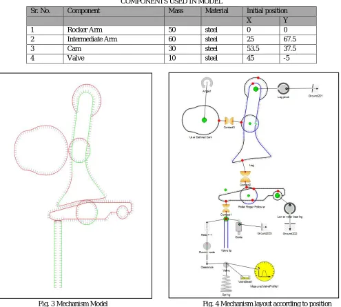
2) Model development: After the study of complete mechanism, VALDYN-kinematic software tool is used to perform kinematic analysis numerically. First step is model development. Model development is done in model mode. In Model mode the user performs all activities associated with building and populating network models. Figure 3 shows the model of proposed mechanism
developed in Model mode and Figure 4 shows the layout of model of proposed mechanism developed in Model mode [6].
[image:4.612.57.552.200.645.2]To change the valve lift, eccentric cam shaft is rotated as explained previously. But in VALDYN, the position of Intermediate arm is rotated by giving the parameter “angle”. For each case different angle is activated and valve lift is changed.
TABLE 1
COMPONENTS USED IN MODEL
Sr. No. Component Mass Material Initial position
X Y
1 Rocker Arm 50 steel 0 0
2 Intermediate Arm 60 steel 25 67.5
3 Cam 30 steel 53.5 37.5
4 Valve 10 steel 45 -5
Fig. 3 Mechanism Model Fig. 4 Mechanism layout according to position
3) Solution setup [6]: In Solution mode the user performs all activities associated with defining and initiating analysis solutions. These activities include:
a) Populating the active session with solution objects from the Library
b) Editing the attributes associated with each solution object
Table 2 Input parameters in model
Sr. No. Parameter Value
1 Maximum angle to analyse 360
2 Angle to start output 90
3 Angle increment for output 15
4 Excitation speed parameter name Omega
[image:5.612.58.535.498.716.2]5 Maximum number of iterations 20
Table 2 shows the input parameters values required for solution in solution mode. Table 3 shows that there are eight cases used to obtain different valve lifts. Omega is constant because it will not have any effect on the valve lift profile in kinematic solution. Angle parameter corresponds to the degree rotation of intermediate arm according to the degree rotation of eccentric cam shaft. After these parameters are set, solution is run to get the results.
Table 3
Angle correspondences in solution mode
Sr. No Case No. Eccentric shaft Angle Case Angle
1 1 0 5.5
2 2 30 4.5
3 3 60 2.8
4 4 80 1.5
5 5 100 -0.2
6 6 115 -1.5
7 7 130 -2.8
8 8 155 -3.8
IV.PROTOTYPEDEVELOPMENT
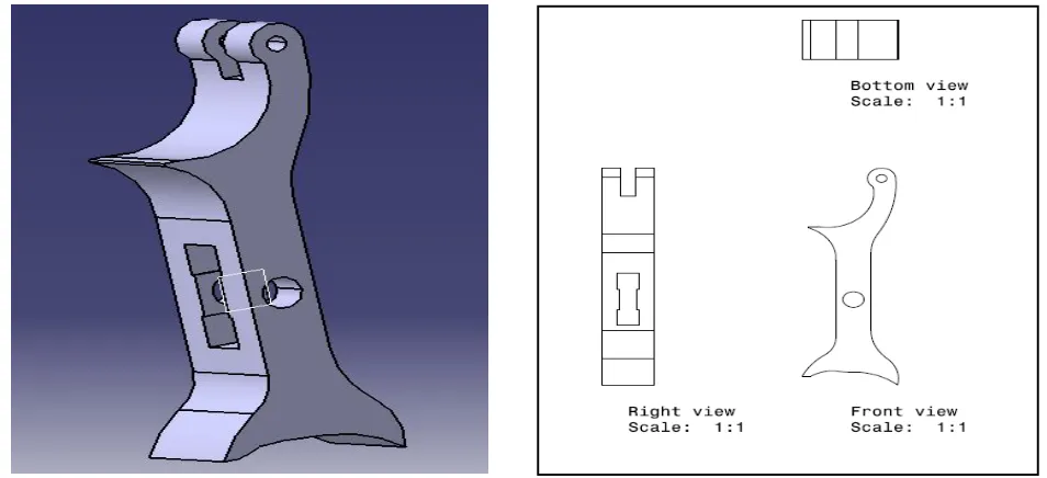
After the completion of kinematic analysis is, the components are designed with suitable dimensions and feasibility of mechanism is checked. Then these components are designed in 3D modelling software CATIA V5R19. These components are manufactured using wire EDM manufacturing process. The engine used to integrate the mechanism is a single cylinder DOHC engine of Bajaj KTM Duke 200.
Fig. 5 Intermediate Lever.
[image:6.612.49.550.360.719.2]Fig. 6 Rocker Arm
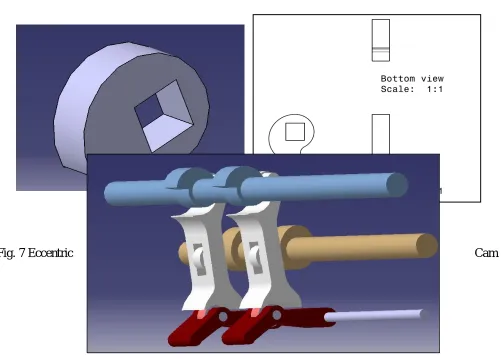
Fig. 8 Model of CVVL Assembly
Figure 8 shows the assembly of components of mechanism. Rocker arm, cam shaft and eccentric camshaft are fixed to the plate from both sides of engine. Intermediate arm is a floating component which is constraint from all sides by Eccentric shaft, camshaft, rocker arm and torsion spring (not shown in assembly). The rocker arm tip is in contact with the valve tip which is present in the engine head.
V. PROTOTYPEDEVELOPMENT
[image:7.612.119.494.418.732.2]In prototype development, components are manufactured and assembled on the engine head of Bajaj KTM Duke 200. The specification of engine and valvetrain is shown in table 4. The exhaust valve was not modified as engine used was DOHC engine; changes were made only on intake valve side. The original rocker arm was replaced with the new rocker arm along with the intermediate arm and eccentric camshaft. The original cam was used but with changed location, to drive intermediate arm.
TABLE 4
BASE ENGINE SPECIFICATIONS (BAJAJ KTM 200) [7] Base Engine Data
Cylinder Specification Value
Bore 72mm
Stroke 49mm
Con. rod length 89.5mm
Cubic capacity 199.50cc
Compression Ratio 11.3:1
Minimum Volume of cylinder Head 14.421cc
Inlet Valves
Number 2
Diameter 28.5mm
Stem Diameter 4.483mm
Length 82.3mm
Maximum Lift 7.7mm
Weight 22.2 gm
IVO 4 BTDC
IVC 26 ABDC
Spring external diameter 17.6mm
Spring wire diameter 2.7mm
No. of spring coils 7.815
Maximum free length of springs 35.7mm
Number 2
Diameter 24 mm
Stem Diameter 4.463mm
Length 78.7mm
Weight 20 gm
EVO 38 BBDC
EVC 1 ATDC
Maximum Lift 6.9mm
Spring external diameter 17.6mm
Spring wire diameter 2.7mm
No. of spring coils 7.815
Maximum free length of springs 35.7mm
Plate 1 Rocker Arm Plate 2 Intermediate Arm
Plate 3 Eccentric camshaft
Plate 5 Final Prototype Assembly
VI.RESULTSANDDISCUSSION
A. Results based on Kinematic analysis ( VALDYN-kinematics)
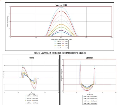
Fig. 9 Valve Lift profile at different control angles
[image:11.612.79.535.509.688.2]Fig. 10 Velocity profile and Acceleration profile at different control angles
Fig. 11 Contact stress between rocker arm to valve and Cam and Intermediate arm
Fig. 12 Measured Valve lift Vs. Crank Angle
To measure the valve lift with respect to crank angle rotation Dial indicator was identified. On the developed CVVL prototype dial indicator was positioned in such a way that valve lift can be measured for given Crank angle rotation. Whereas to measure the crank angle rotation a procircle was fitted on the prototype in such a way that cam shaft centre coincides with procircle centre and marker was integrated on the camshaft. For the requisite cam angle rotation, the camshaft handle is rotated and for that particular angle the dial indicator reading were noted. The whole exercise was carried out with crank angle interval of 10o. The readings were noted from base circle position to maximum lift position. Also the graph depicting the measured valve lift versus the crank angle rotation is shown in figure 12.
VIII. COMPARISONOFVALVELIFT(MAXIMUMANDMINIMUM)
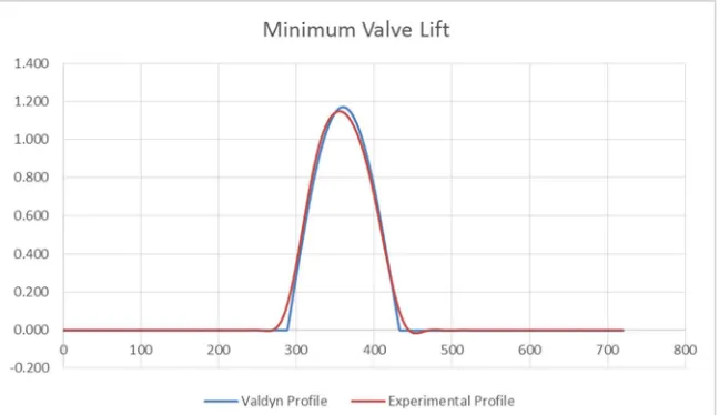
Valve profile obtained through kinematic analysis and developed prototype for maximum and minimum lift
are compared. It shows valve lift between two extreme valve heights
i.e. from minimum 1.2mm to
maximum 7.7 mm. It is observed that prototype valve profile very well follows the kinematic analysis based
profile at all the critical points and intermediate points and variation is within the permissible limit.
[image:12.612.166.487.469.631.2]Fig. 14 Comparison of Minimum Valve Lift
IX.CONCLUSIONS
This paper presents the kinematic analysis of novel CVVL mechanism with three elements which carried out in Ricardo VALDYN-Kinematic and prototype development of the same.
A. Kinematic analysis using simulation software Ricardo VALDYN-Kinematics is carried out.
B. The kinematic analysis shows that the mechanism ensures a continuous valve lift between two extreme valve heights i.e. from minimum 1.2mm to maximum 7.7 mm.
C. The prototype of proposed mechanism is successfully retrofitted on 200cc DOHC single cylinder four valve motorcycle engines. It successfully demonstrates the continuous variable valve lift i.e. from minimum 1.2mm to maximum 7.7mm.
D. The Contact stress between the cam and roller follower is found to be 916 MPa which is within the acceptable permissible limit of 1240 MPa for all the cam rotation angles of all control angle
.E. The Contact stress between the rocker arm tip and valve is found to be MPa which is not exceed the allowable limit of 1240
MPa for all the cam rotation angles of all control angle
F. Kinematic analysis with Ricardo VALDYN-Kinematics shows good agreement with results obtained by a developed prototype.
G. The CVVL mechanism is a potential variable valve actuation technology which offers throttle-free load control for small capacity single cylinder SI engine.
REFERENCES
[1] Santosh. B. Trimbake and Dr. D. N. Malkhede - “Strategies for HCCI/CAI Combustion Control using Residual Gas” SIAT, Technical Reference bulletin, Jauary 2015
[2] Megha A. Mohite, Eknath N. Aitavade, “Novel Continuous Variable Valve Lift (CVVL) Mechanism for Throttle Free Load Control of SI Engine” International Engineering Research Journal, Volume 2, Issue 3, Page 989-997, ISSN 2395-1621, May 2016
[3] Ludwig, B., “Less CO2 Thanks to the BMW 4-Cyl. Valvetronic Engine”, ATA International Conference on Spark Ignition Engine: The CO2 Challenge, Paper 02A5011, Venezia, Italy, November, 2002.
[4] Stelian. Mihalcea.,“A kinematic analysis of the valve timing mechanism with three elements and continuous valve lift”, ISSN 1453-7397, 2010.
[5] Stelian Michalcea, N.D. Stanescu and Dinel Popa, "Synthesis and Kinematic and dynamic Analysis of a variable valve lift mechanism with General Curve Contact", Journal of multibody dynamics 2015, vol. 229(l) 65-83, Sage.
[6] VALDYN Kinematics User Manual, Ricardo Software, Version: 2015.1
![TABLE 4 BASE ENGINE SPECIFICATIONS (BAJAJ KTM 200) [7]](https://thumb-us.123doks.com/thumbv2/123dok_us/8304863.855676/7.612.119.494.418.732/table-base-engine-specifications-bajaj-ktm.webp)