Cold Load Pick-Up for Refrigerators
Ankit Rai1, Dr. Ranjana Singh2 Jabalpur Engineering College, Jabalpur (M.P)
Abstract: Cold load pickup is the phenomenon that takes place when a distribution circuit is re-energized following an extended outage of that circuit. This phenomenon is referred to as cold load pickup because the power supply has been unavailable for a period of time so that the load has reached a “cold” state before being re-energized. It is seen that effect of cold load pickup is more on thermostatic load (refrigerators, air-conditioners, room heaters etc). This paper presents measurements of cold load pickup for refrigerators. Measurements have been performed on seven refrigerators at summer season. Firstly current has been measured on running condition. After that the power supply has been switched off for 3 hours. Then power supply has been switched on and current has been again measured step by step up to normal level. Cold load pickup has been measured on refrigerators based on that reading.
I. INTRODUCTION
Cold Load Pickup is the phenomenon that takes place when a power distribution circuit is re- energized following an outage of that circuit for several minutes to several hours. When the circuit is reenergized two conditions are occurring which increases the current on that circuit above the pre-outage level. The two conditions are inrush to re-energize the loads and the pickup of more connected load due to the loss of diversity of the load. Loads that are connected at all times but are cycled on and off based on temperature or pressure reach a level of diversity once the power circuit has been energized for a period of time. Following an interruption of service to this circuit the diversity is lost and most or all of these cycling loads will be connected, drawing power for a period of time following the re-energization of the circuit. The current flow to the circuit may be significantly greater than the normal level.
II. REFRIGERATORS AND FREEZERS
The basic design of a refrigerating system can be described by figure 1. It consists of an evaporator, a condenser, a compressor and an expansion valve. In the evaporator the refrigerant is vaporized at a low temperature, Tv, and low pressure, Pv. Vaporization is due to the temperature difference between the refrigerating medium, Tv, and the refrigerating room, Ti. The capacity of an evaporator is linearly dependent on this temperature difference. In order to keep the pressure and temperature in the evaporator at a constant level a mass flow, m, is generated by the action of the compressor.
The compressor transports the mass flow in a closed loop and keeps the pressure in the condenser on a high level. As a result of the compression the temperature on the condenser side will increase. Reciprocating compressors are the most common used for refrigerating purposes. This type of compressor theoretically compresses a constant volume. In reality, however, the volumetric efficiency is inversely proportional to the compression ratio and actual tests show that the total volum-
metric efficiency will be rather constant for a given compression ratio. The capacity and efficiency of a compressor varies considerably with the system operating conditions. The largest impact on the compressor capacity is related to the vaporizing temperature in the evaporator. An increase of the vaporizing temperature will result in a higher pressure and thereby an increased density of the vapour. Each volume of vapour compressed will then consist of a larger mass of refrigerant. An increased vaporizing pressure will reduce the compression ratio and thereby improve the volumetric efficiency. The largest part of the capacity increase is, however, related to the higher vapour density.
A variation in the condenser temperature will not affect the compressor capacity as much as a change in the vaporizing temperature. This since the condenser temperature does not have an influence on the density of the vapour compressed. However, a change in the condensing temperature will change the condenser pressure and the compression ratio and thereby also the volumetric efficiency. The power consumption of the compressor is mainly dependent of the mass flow and the compression ratio. A higher mass flow will in the same way as a higher compression ratio increase the power consumption.
The condenser works approximately in the same way as the evaporator. Instead of absorbing heat the condenser gives away the heat absorbed in the evaporator and the energy of the work done by the compression. In the same way as for the evaporator the capacity of a condenser is linearly dependent with the temperature difference between the condenser and the ambient temperature. Before the liquid comes back to the evaporator the pressure has to be reduced and this is done in the expansion valve. The most common type of expansion valve is the capillary tube which is a tube with a small diameter installed between the condenser and evaporator. The mass flow through the capillary tube is proportional to the difference between the condenser and evaporator pressure. During the off cycle the capillary tube will not close and therefore the high and low side pressures will equalize. This will reduce the starting up power compared with if the capillary tube would have been closed. This means that it is possible to use a motor with a low starting torque for the compressor.
During a disturbance in the power supply the temperature inside the cooling equipment will rise and the pressure in the condenser and evaporator will be equalized. After the initial phase when the compressor starts and the pressure in the condenser increases a quasi stationary level with a quasi constant mass flow will be achieved. The higher temperature inside the refrigerating equipment will increase the evaporator temperature which will result in a higher evaporator pressure. This gives an increased density in the evaporator and consequently also a larger mass flow through the compressor. The power consumption of the compressor will increase due to the higher mass flow. As the pressure in the evaporator and the condenser will change, also the compression ratio and thereby the volumetric efficiency will be affected. However, the condenser pressure increases more than the evaporator pressure and therefore the compression ratio will not be changed so much.
III. PROCEDURE
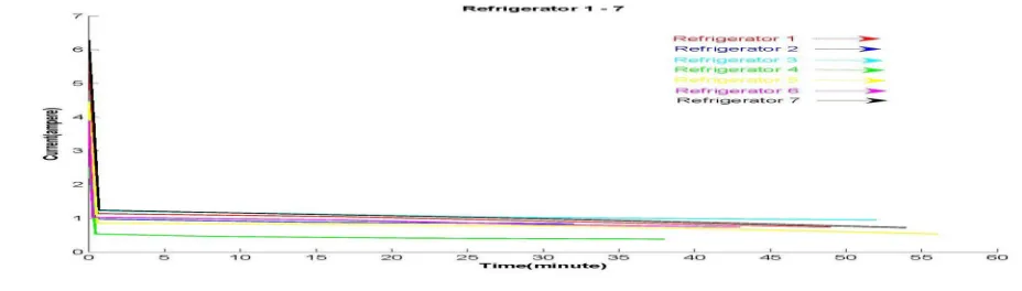
[image:3.612.63.527.579.711.2]In order to study the behaviour after a disturbance measurements have been performed on seven refrigerators in summer season. Firstly current has been measured on normal running condition of refrigerator. After that the power supply has been switched off for 3 hours so the refrigerator comes into cold state. Then power supply has been switched on and current has been again measured up to normal level.
Fig 2 shows the current time graph of seven refrigerators. As shown in fig 2 the current after restoration is very high. Current comes in to normal state after several minutes.
Fig 3 shows the current time graph of seven refrigerators but it’s an enlarged view of this graph for a time up to 5 minutes.
Fig [3] – Current and Time graph of refrigerators in cold load pickup condition
[image:4.612.82.530.31.451.2]Table 1 shows the current value in normal running condition and cold load pickup value. It also shows the duration and percentage of cold load pickup.
Table -1 Current measurement in refrigerators in cold load pickup condition:
Serial no of Refrigerator Cold load pickup
time (minute)
Peak current
(ampere)
Normal current (ampere)
Percentage of
cold load
pickup (%)
Refrigerator 1 49 5.95 0.74 804.0541
Refrigerator 2 32 3.58 0.84 426.1905
Refrigerator 3 52 4.48 0.95 471.5789
Refrigerator 4 38 2.52 0.38 663.1579
Refrigerator 5 56 4.44 0.53 837.7358
Refrigerator 6 43 3.89 0.74 525.6757
Refrigerator 7 54 6.29 0.72 873.6111
IV. CONCLUSION
[image:4.612.71.541.521.682.2]As shown in fig 2 the initial current in various refrigerators varies from 4.26 to 8.73 times of normal current. Cold load pickup current comes into normal state after several minutes i.e. 32 minutes to 56 minutes. In this duration the overload on the distribution transformer takes place, which is one of the reason of failure of distribution transformer.
REFERENCES
[1] L.J. Audlin. M.H. Pratt and AJ. McConnell."New Relay Assures Feeder Resumption after Outage", part I & 2, Electrical World. September 10, 1949, pp 99-103 & September 24, pp. 95-9S, 1949
[2] J.E. McDonald , A. M.Bruning and W.R.Mahieu, "Cold load Pickup", IEEE Trans.Power Appar.Syst., 1979, PAS-98,(4), pp. 1384-1386
[3] C.Y. Chong and A.S. Debs, Statistical synthesis of power systemfunctional load models, Proc. 18th 1EEE Conj. Decision and Control, Fort Lauderdale, FL, USA, 1979, IEEE, New York, pp. 264- 26
[4] R.L.Wilde, "The Effects of Cold Load Pickup on Distribution Transformer"IEEE Trans Power Appar.Syst., 1981, PAS-100,(5), pp. 2433-2437 [5] S. lhara and F.C. Schweppe, Physically based modeling of coldload pickup, IEEE Trans. Power Appar. Syst., PAS-IO0 (1981) 4142 4150.
[6] Chee Yee Chong, R. P. Malhami, " Statistical Synthesis of Physically Based Load Models with Applications to Cold load Pickup "1984, PAS-103,(7), pp. 1621-1629.
[7] R.E. Mortensen and K.P. Haggerty, A stochastic computer model for heating and cooling loads, IEEE Trans. Power Syst., 3 (1988) 1213-1219. [8] Vijay and Rao"An Expert System for Cold Load Pickup" M.S. Thesis,Department of Electrical Engineering. Montana State University, August 1994. [9] Canbolat Ukak, Anil Pahwa, "Optimal step by step restoration of distribution systems during excessive loads due to cold load pickup ", Electric Power Systems
Research 32(1995), pp 121-128.
[10] E.Agneholm, J. Daalder, "Cold Load Pick-up for Individual Load Objects", 33rdUniversities Power Engineering Conference, chap. 3, page 20, 1999. [11] E.Agneholm, J. Daalder ,"Cold load Pickup of Residential Load" IEEE Proc.-Gener. Transm. Distrib., Vol. 147(1),2000.3]
![Fig [3] – Current and Time graph of refrigerators in cold load pickup condition](https://thumb-us.123doks.com/thumbv2/123dok_us/8309258.857460/4.612.82.530.31.451/fig-current-time-graph-refrigerators-cold-pickup-condition.webp)
