Design of an Adaptive Controller of a Satellite
using Thruster Actuator
Alireza Fazlyab
Department of Mechanical Engineering, Amirkabir University of Technology
Tehran, Iran
Abbas Ajorkar
Department of Mechanical Engineering, Amirkabir University of Technology
Tehran, Ira
Mansour Kabganian
Department of Mechanical Engineering, Amirkabir University of Technology
Tehran, Ira
ABSTRACT
In this paper, an attitude control algorithm for a satellite is developed based on adaptive control using thruster actuators. For this purpose a twelve-thruster arrangement has been considered and the control torque for each thruster has been calculated. Then a Pulse Width-Pulse Frequency (PWPF) modulator is used for converting continuous controller signals into equivalent discrete one. Then, uncertainties in the moment of inertia matrix and disturbances torque has been considered and adaptive attitude control using feedback linearization controller with self-tuning regulator (Least Square Estimator With Bounded Gain Factor) is used. Finally, the performance of the designed attitude controller is investigated by simulations.
Keywords
Attitude Control; Adaptive control; Satellite; Reaction Thruster; PWPF modulator.
1.
INTRODUCTION
A spacecraft to accomplish its mission, requires several subsystems. Attitude determination and control system (ADCS) is one of the most crucial subsystems of the spacecraft. The controller algorithm is an essential part of ADCS subsystem that provides commands for actuators [1]. Various actuators are used for attitude control, and thruster is one of the most important of them. Thrusters are used in situation when disturbance torques exceed the control authority of the other actuators, and are often capable of much faster reorientation maneuvers. Thrusters have been used to maintain stability during translational maneuvers [2]. Reaction thrusters are activated in a pulsing mode only. There are no linear, continuous reaction thruster controllers; so attitude control with thrusters is a challenging task.
Two major methods for thruster control are bang-bang control and pulse modulation. Bang-bang control is simple in formulation, but results in excessive energy consumption [3, 4]. Since fuel consumption is a principal factor in the life of the spacecraft, bang-bang control is not a good way to control the thrusters. On the other hand, pulse modulators are popular due to their advantages of reduced propellant consumption. In general, pulse modulators produce a pulse command sequence to thruster valves by adjusting pulse width and/or pulse frequency [5]. So far different Pulse modulators such as pseudo-rate modulator [6], integral-pulse frequency modulator [7, 8] and Pulse-Width Pulse-Frequency (PWPF) modulator [9, 10, 11, 12] have been proposed and examined. In comparison with others, the PWPF modulator has several superior advantages such as close to linear operation, high accuracy and adjustable pulse width and pulse frequency [5].
Among the research that has been done recently, there are a number of techniques that can deal with the control problems of such a complex dynamic system from classical PID control to adaptive control e.g. optimal control [13], sliding mode control [14], adaptive control [15, 16, 17, 18], robust control such as variable structure control (VSC) which are designed based on Euler angle errors or quaternion error vector.
In [13, 14, 19] satellite dynamics is assumed to be perfectly known. But in practice, satellite parameters are not precisely known. In addition, the external disturbance torques such as gravity gradient, solar pressure, earth magnetic field, atmosphere drag and etc. are applied to the satellite constantly. In order to execute a precise calculation of these disturbances the system parameters should be known.
In [15, 16, 17, 18], due to the use of adaptive control, there is no need for all parameters to be known but the effect of actuator dynamics on results has not been studied and speed of parameter estimation is very low.
In this paper, an adaptive attitude control of a satellite in presence of thruster dynamics and uncertainties in the moment of inertia matrix and disturbances torque has been designed. For adaptive control law, feedback linearization controller with self-tuning regulator is used. Finally we have evaluated the performance and speed of adaptive controller with simulation.
2.
DYNAMIC AND KINEMATICS OF
SATELLITE
For mathematical modeling, we suppose spacecraft as a rigid body. The general equation to describe the attitude motion of a rigid body in space (Euler equations) is described as follows [4]:
(1)
) (
) (
) (
x y y y z z z
z x z x y y y
y z z y x x x
I I I
M
I I I
M
I I I
M
Where,
x,y,z
Tis angular velocity of spacecraft whit respect to body reference frame. I is the inertia matrix and M represents the control torques used for controlling the attitude.
4 13
q q q
(2)
2 sin ˆ
3 2 1
13
n q q q q
(3)
2 cos
4
q (4)
Where nˆ is a unit vector corresponding to the axis of rotation
and is the angle of rotation.
The kinematic equations of motion are derived by using the satellite’s angular velocity (
) by equation (5).(5)
4 3 2 1
4 3 2 1
0 0 0 0
2 1
q q q q
q q q q
z y x
z x
y
y x z
x y z
q q q q
TQ 1 2 3 4
q1 q2 q3
QV
3.
THRUSTERS ARRANGEMENT AND
PWPF MODULATOR
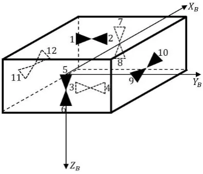
Algorithm used here transforms the torque commands into correctly time activation of the relevant thrusters. The algorithm naturally depends on the physical set-up shown in Fig 1, which is a twelve thrusters set-up for an satellite.
Fig 1 : Arrangement of twelve thrusters
The set-up in Fig 1 allows for 3 axes attitude control. In this structure each two thrusters produce torque only along one axis and have no effect on other axes. For example Thrusters 1 and 4 provide the negative control torques about X axis; thruster 2 and 3 provides positive torque about the X axis and so on. For simplicity assume that the thrusters are located symmetrically about the body axes, with equal torque arms about the same axis; the direction of the thruster axes are
is the ratio between the thruster “on-time” and the sampling time for thruster number.
(6)
z y x
T
T T T
T T T T T T T T T T T T
1 0 0
1 0 0
1 0 0
1 0 0
0 1 0
0 1 0
0 1 0
0 1 0
0 0 1
0 0 1
0 0 1
0 0 1
2 1
12 11 10 9 8 7 6 5 4 3 2 1
[image:2.595.56.237.255.360.2]A PWPF modulator produces a pulse command sequence to the thruster valves by adjusting the pulse width and pulse frequency. As shown in Fig 2, the PWPF modulator is comprised of a Schmidt Trigger, a pre-filter and a feedback loop. A Schmidt Trigger is simply an on-off relay with dead-zone and hysteresis. Due to nonlinear nature of the modulator, analytic methods such as describing function cannot produce accurate prediction over a large operation range. Instead, extensive numerical simulations have been carried out to study the effects of these parameters on the performance of the modulator. In this paper the results of the numerical studies are presented. The preferred range of parameters through extensive simulations is listed in Table 1 [20].
[image:2.595.318.544.423.537.2] [image:2.595.69.267.444.614.2]Fig 2 : A PWPF Modulator
Table 1. Recommended range of PWPF parameters Paramete
rs
Static Analysis
Dynamics Analysis
Recommende d Settings
m
K 2Km6 N/A 2Km6
m
T N/A 0.1m0.5 0.1m0.5
on
e Uon0.3 N/A Uon0.3
off
[image:2.595.309.548.579.759.2]4.
ADAPTIVE CONTROL DESIGN
For the design of adaptive control, first the feedback linearization controller is designed, then a self-tuning regulator is used to estimate the system’s uncertainty
4.1
Feedback linearization control design
In feedback linearization design, the states are assumed to be the vector part of quaternion parameters.
(7)
q1 q2 q3
QV
In equation (1), that represents the dynamics equation of system, Mi(ix,y,z) is equal to the sum of control torque (
ci
M ) and disturbances torque (Mdi).
(8) ) ( ) ( ) ( x y y y z z dz cz z z x z x y y dy cy y y z z y x x dx cx x I I I M M M I I I M M M I I I M M M
We choose the control moment as follow:
(9) dz dy dx y x y y x z z x z y z y e V e V d c M M M I I I I I I Q K Q K I M ) ( ) ( ) (
( 1 0
Where, K12I and K02I are the coefficient matrices for the desired dynamic model of controlled system and is a
positive constant. Also, QVe is the vector part of the error quaternion. The error quaternion and the error quaternion dynamics is defined as follow: [21]
(10) Q
Q Qe( d)1
(11) ) ~ ) ( 2 1 , ~ )) ( ( 2 1 ( 2 1 0 ~
e e e eT
e q q S I q Q Q Q
Where, is the quaternion multiplication and the desired orientation or desired quaternion to be track (Qd) is given by: (12)
d 0
d Q
(13) d d d Q Q
Q
2 1
Where, d is the desired angular velocity. In equation (11), )
(qe
S define as equation (14). Also ~d, that d represents desired angular velocity respect to the body frame which is obtained by multiplying the transformation matrix
) (Q
R in d.(equation (15)-(17))
(14) 0 0 0 ) ( 1 2 1 3 2 3 q q q q q q q S (15) d ~ (16) d e T dR Q
( ) (17) ) ( 2 2 ) ( ) ( 2 ) ( 2 ) ( 0 2 0 2 0 q S q Q Q I Q Q q q S q S q I Q R T V V V T
V
By placing the control law in the dynamics of the system, the system dynamic error is zero (equation (18)). That means the exponential stability is guaranteed.
(18) 0 2 ~ 2 e V e V Q Q
4.2
Self-tunning regulator (STR) design
To estimate the unknown parameters of the designed controller, the self-tuning regulator (STR) has been used. We use the least square estimator with bounded gain factor. The principal equation for parameter estimation is as follow:
(19) p T e W t p aˆ ()
Where,a is parameter estimation, p(t) is the estimator gain matrix that is be changed with time. WT is signal matrix and
p
e is prediction error. p(t) is updated as follow:
(20)
P t P PW tWt P dt d T ) ( ) ( ) ( ) (t , is obtained as follow:
(21) ) 1 ( ) ( 0 0 L P t
With 0 and L0 being positive constants representing the maximum forgetting rate and prespecified bound for gain matrix magnitude, respectively.
In this method, signal matrix (W(t)), and unknown parameters (a) are obtained by linear parameterization of system dynamics. So, initially we have to sort the dynamics equation of the system.
(22) dz x y y y z z cz dy z x z x y y cy dx y z z y x x cx M I I I M M I I I M M I I I M ) ( ) ( ) (
(23)
dz dy dx z y x
z y x y x
z x y
z x
z y z y x
i ij cz cy cx
M M M I I I a
W M M M Y
1 0 0
0 1 0
0 0 1
WhereY, contains the outputs of the system. Note that both Y and
Wij are required to be known from the measurements of the system signals, and thus the only unknown quantities are the parameters in
ai .5.
SIMULATION AND RESULTS
In this section, to demonstrate the performance of feedback linearization controller and designed adaptive controller to track the desired path and effect of uncertainty on them, three different scenarios are proposed.
1) Feedback linearization controller without parameter estimation and uncertainty
2) Feedback linearization controller without parameter estimation and in presence of uncertainty
3) Adaptive controller in the presence of uncertainty
In all simulations, desired angular velocity are considered as )
05 . 0 sin( 1 .
0 t
dx
, dy0.1sin(0.05t) and )
05 . 0 sin( 1 .
0 t
dz
[image:4.595.53.249.70.207.2] . Moreover, satellite dynamics model, thrusters, PWPF and controller Parameters and initial conditions are summarized in Table 2.
Table 2. Simulation parameters
Subsystem Parameter Quantity
PWPF
Modulator
m
K 2
m
T 0.5
on
U 1
off
U 0.1
m
U 1
k 10
Satellite
Dynamics
z y
x I I
I
1000 500 700
Kg.m2
0 0 0
0 0 0
deg
x0 y0 z0
0 0 0
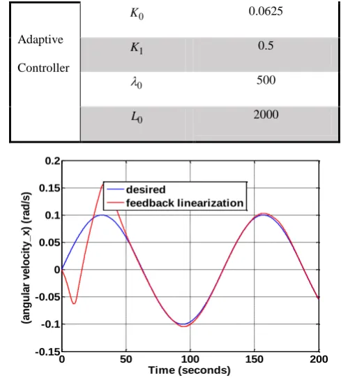
rad/secAdaptive
Controller
0
K 0.0625
1
K 0.5
0
500
0
[image:4.595.303.548.71.342.2]L 2000
Fig 3 : Performance of feedback linearization controller without parameter estimation and uncertainty for
[image:4.595.319.524.388.550.2]tracking of desired angular velocity of X axis
Fig 4 : Performance of feedback linearization controller without parameter estimation and uncertainty for
tracking of desired angular velocity of Y axis
0 50 100 150 200
-0.15 -0.1 -0.05 0 0.05 0.1 0.15 0.2
Time (seconds)
(a
n
g
u
la
r
v
e
lo
c
it
y
_
x
)
(r
a
d
/s
) desired
feedback linearization
0 50 100 150 200
-0.25 -0.2 -0.15 -0.1 -0.05 0 0.05 0.1 0.15
Time (seconds)
a
n
g
u
la
r
v
e
lo
c
it
y
_
y
(
ra
d
/s
e
c
o
n
d
)
desired
Fig 5 : Performance of feedback linearization controller without parameter estimation and uncertainty for
tracking of desired angular velocity of Z axis
Fig 6 : Tracking error of desired angular velocity for feedback linearization controller without parameter
[image:5.595.319.542.79.489.2]estimation and uncertainty
Fig 7 : Tracking error of desired angular velocity for feedback linearization controller without parameter
[image:5.595.55.277.81.249.2]estimation and in the presence of uncertainty
Fig 8 : Tracking error of quaternions
e e e e
e q q q q
Q 0 1 2 3
for feedback linearization controller without parameter estimation and in the
presence of uncertainty
Fig 9 : Tracking error of desired angular velocity for adaptive controller in the presence of uncertainty
Fig 10 : Tracking error of quaternions
0 50 100 150 200
-0.1 -0.05 0 0.05 0.1 0.15
Time (seconds)
a
n
g
u
la
r
v
e
lo
c
it
y
_
z
(r
a
d
/s
e
c
o
n
d
) desired
feedback linearization
0 50 100 150 200
-0.1 -0.05 0 0.05 0.1 0.15 0.2 0.25 0.3
time(second)
t
ra
c
k
in
g
e
rr
o
r
tracking error-x tracking error-y tracking error-z
0 100 200 300 400 500
-0.2 -0.15 -0.1 -0.05 0 0.05 0.1 0.15
time(second)
a
n
g
u
la
r
v
e
lo
c
it
y
e
rr
o
r
angular velocity error-x angular velocity error-y angular velocity error-z
0 500
-0.5 0 0.5 1
Time (seconds)
qe
0
0 500
-0.5 0 0.5 1
Time (seconds)
qe
1
0 500
0 0.5 1
Time (seconds)
qe
2
0 500
-0.5 0 0.5 1
Time (seconds)
qe
3
0 100 200 300 400 500
-0.05 0 0.05 0.1 0.15 0.2
time(second)
a
n
g
u
la
r
v
e
lo
c
it
y
e
rr
o
r
angular velocity error-x angular velocity error-y angular velocity error-z
0 200 400 600
-0.5 0 0.5 1
Time (seconds)
qe
0
0 200 400 600
-0.02 -0.01 0 0.01 0.02
Time (seconds)
qe
1
0 200 400 600
-0.5 0 0.5 1
Time (seconds)
qe
2
0 200 400 600
-0.01 0 0.01 0.02 0.03
Time (seconds)
qe
[image:5.595.58.263.536.700.2] [image:5.595.330.540.560.731.2]
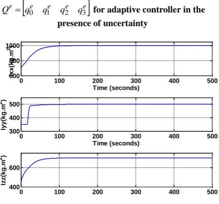
e e e e
e q q q q
Q 0 1 2 3 for adaptive controller in the
[image:6.595.65.282.72.273.2]presence of uncertainty
Fig 11 : Estimation of moment of inertia parameters by adaptive controller
Fig 12 : Estimation of external disturbances by adaptive controller
1) Fig 3 to Fig 6 show the result of feedback linearization controller without parameter estimation and uncertainty. As it is seen in Fig 6, the tracking error converge to zero and feedback linearization can track the desired angular velocity, properly.
2) Fig 7 and Fig 8, show the result of feedback linearization controller without parameter estimation in the presence of 25 percent uncertainty in the moment of inertia matrix and disturbances torque. The results show, the tracking error doesn’t converge to zero. Hence this attitude control algorithm doesn’t satisfy the attitude control requirements in the presence of uncertainty.
3) Fig 9 and Fig 10, show the result of adaptive controller (with parameter estimation) in the presence of 25 percent
estimation of moment of inertia and disturbances torque respectively.
6.
CONCLUSION
In this paper, an attitude control algorithm in the presence of twelve thruster as the satellite actuator is designed based on adaptive control. Then a Pulse Width-Pulse Frequency (PWPF) modulator is used for converting continuous controller signals into equivalent discrete one that are applied to nonlinear dynamics of satellite.Then, adaptive attitude control using feedback linearization controller with self-tuning regulator in the presence of uncertainties in the moment of inertia matrix and disturbances torque has been designed. Finally, the simulation results in three different scenario, show that the designed adaptive attitude controller can decrease the tracking error and increase the accuracy of the system performance in the presence of uncertainty.
7.
REFERENCES
[1] Bagheri, M., Kabganian, M., and Nadafi, R. 2012. Stable Design of Attitude Control for a Spacecraft. In IAA Conference on Dynamics and Control of Space Systems, Porto.
[2] Wie, B., and Plescia, C. 1984. Attitude Stabilization of Flexible Spacecraft During Station keeping Maneuvers. Journal of Guidance and Control, vol. 7, pp. 430-436.
[3] Shuster, M. D. 1993. A Survey of Attitude Representations. The Journal of the Astronautical Sciences, vol. 41, pp. 439-517.
[4] Sidi, M. J. 1997. Spacecraft Dynamics and control: a practical engineering approach. Cambridge: Cambridge University Press.
[5] Gangbing, S., and Agrawal B, N. 1999. Vibration Reduction for Flexible Spacecraft Attitude Control Using PWPF Modulator and Smart Structures. In IEEE Aerospace Conference.
[6] Millar, A., and Vigneron, F. 1976. Attitude Stability of Flexible Spacecraft Which Use Dual Time Constant Feedback Lag Network Pseudorate Control. in Communications Satellite Systems Conference, Montreal.
[7] Clark, R., and Franklin, G. 1969. Limit Cycle Oscillations in Pulse Modulated Systems. Journal of Spacecraft and Rockets, vol. 6, pp. 799-804.
[8] Hablani, H. 1994. Multiaxis Tracking and Attitude Control of Flexible Spacecraft with Reaction Jets. AIAA Journal of Guidance, Control and Dynamics, vol. 17, pp. 831-839.
[9] Anthony, T., Wie, B., and Carrol. 1990. Pulse-Modulated Control Synthesis for a Flexible Spacecraft. AIAA Journal of Guidance, Control and Dynamics, vol. 13, pp. 1014-1015.
[10] Song, G., Buck, N., and Agrawel, B. 1998. Spacecraft Vibration Reduction Using Pulse-Width Pulse-Frequency Modulated Input Shaper. AIAA Journal of Guidance,
0 100 200 300 400 500
600 800 1000
Time (seconds)
Ix
x
(k
g
.m
2)
0 100 200 300 400 500
300 400 500
Time (seconds)
Iy
y
(k
g
.m
2)
0 100 200 300 400 500
400 600
Izz(
k
g
.m
2)
0 100 200 300 400 500
0 5 10
Time (seconds)
Md
x
(N
.m
)
0 100 200 300 400 500
0 5 10
Time (seconds)
Md
y
(N
.m
)
0 100 200 300 400 500
0 5 10
Time (seconds)
Md
z
(N
.m
[image:6.595.64.283.315.489.2][11] Qinglei, H., and Yaqiu, L. 2005. A Hybrid Scheme of Feed-forward/Feedback Control for Vibration Suppression of Flexible Spacecraft with On-Off Actuators during Attitude Maneuver. Internationa Journal of Information Technology, vol. 11, pp. 95-107.
[12] Xingyuan, X., and Yuanli, C. 2011. Width Pulse-Frequency Based Optimal Controller Design for Kinetic Kill Vehicle Attitude Tracking Control. Applied Mathematics, vol. 2, pp. 565-574.
[13] Chelaru, T. V., Cristian, B., and Chelaru, A. 2011. Mathematical model for small satellites, using rotation angles and optimal control synthesis. In Recent Advances in Space Technologies (RAST), Istanbul, Turkiye.
[14] Qinglei, H. 2008. Sliding mode maneuvering control and active vibration damping three axis stabilized flexible spacecraft with actuator dynamics. Nonlinear Dynamics, vol. 15, pp. 227-248.
[15] Moradi, M. 2013. Self-tuning PID controller to three-axis stabilization of a satellite with unknown parameters. International Journal of Non-Linear Mechanics, vol. 49, pp. 50-56.
[16] Shahravi, M., and Kabganian, M. 2005. Attitude tracking and vibration suppression of flexible spacecraft using implicit adaptive control law. In American Control Conference, Portland, OR, USA.
[17] Shahravi, M., Kabganian, M., and Alasty, A. 2006. Adaptive robust attitude control of a flexible spacecraft. International Journal of Robust and Nonlinear Control, vol. 16, no. 6, pp. 287-302.
[18] Guan, P., Liu, X. –J., and Liu, J. Z. 2005. Adaptive fuzzy sliding mode control for flexible satellite. Engineering Applications of Artificial Intelligence, vol. 18, no. 4, pp. 451-459.
[19] Song, Z., Li, H., and Sun, K. 2014. Finite-time control for nonlinear spacecraft attitude based on terminal sliding mode technique. ISA Transactions, vol. 53, no. 1, pp. 117-124.
[20] Hu, Q. 2009. Variable Structure Maneuvering Control with Time Varying Sliding Surface and Active Vibration Damping of Flexible Spacecraft with Input Saturation. Acta Astronautica, vol. 64, pp. 1085-1108.