Comparative Analysis of a Circularly Polarized
Microstrip Antenna with a Cross-Slot using Single and
Double Substrate
Raj Gusain
M.Tech student DIT University, Dehradun Dehradun (Uttarakhand), India
Sandip Vijay
Professor
DIT University, Dehradun Dehradun (Uttrakhand), India
ABSTRACT
This paper compares the different parameters for differently configured single substrate circular patch and double substrate square patch microstrip antenna. The proposed antenna 1 is fed by proximity coupled feed whereas the proposed antenna 2 is single fed to excite the antenna. Copper clad substrate is used in this design. The circular polarization is achieved by the proposed antennas without 90° hybrid coupler. The proposed antennas are applicable for L and S band applications (1.26GHz and 2.56/2.65 GHz respectively). The gain of both of the antenna are approximately same. This comparison will provide the technique for miniaturization using single substrate.
Keywords
Microstrip patch antenna, dual band, return loss, circular polarization, HFSS.
1.
INTRODUCTION
The microstrip patch antennas are widely used in the field of wireless systems, satellite, navigation and communication systems because of their low cost, low volume, light weight and conformal nature [1]. GPS, mobile satellite, RADAR system and RFID design uses circularly polarized microstrip antennas for their operation [2].
Circular polarization is defined as the superposition of 2 linear polarized modes with quadrature phase excitations and equal amplitude. Circular polarization is achieved through radiating elements like square, circular and triangular patches either through single fed or double fed feeding techniques [3]. The circularly polarized antennas are helpful in reducing multipath fading due to which spectral efficiency, impedance and axial bandwidth of RF system is increased. The data transmission in circular polarization does not depend on the orientation of the transmitter and receiver. The incoming waves of any polarization can be received with a left hand circularly polarized antenna but in the case of right hand circularly polarized antenna it is vice-versa [4].
Now-a-days wireless communication system use circular polarization because it can provide better mobility, weather penetration, flexibility in orientation angle and reduction in multipath reflection as compared to linear polarization[5]. Axial ratio and tilt angle are the two parameters in polarization. For linear polarization axial ratio is infinite and orientation is defined by tilt angle whereas in the case of circular polarization axial ratio equals to unity. The quality of the circularly polarized wave is specified by axial ratio[6]. Circularly polarized microstrip antennas use single and dual-feed structure. The larger circularly polarized bandwidth is
achieved by dual-feed structure but feeding network requires larger ground plane size in comparison with the single feed structure. For single feed structure the slight perturbation of the antenna structure at appropriate location is done to excite orthogonal modes with phase shift of 90° w.r.t the feed for achieving circular polarisation. For achieving circular polarisation radiation of single-feed circularly polarized microstrip antenna different types of perturbation techniques are employed example truncating corners, introducing slits, notches, stubs, embedded slot onto the patch[7].
Another advantage of circularly polarized antennas is they can reduce the effects of Faraday rotation and can also communicate better with a linearly polarized antenna for some specific applications such as long distance satellite communication system and short distance radio frequency identification system. But designing a circularly polarized antenna involves adjustment of some parameters which increases manufacturing difficulties ultimately reducing the production yield rate [8].
Circularly polarized printed slot antennas are widely used in satellite communication and recent wireless communication application due to their advantages such as large impedance bandwidth, low profiles and wide 3dB axial ratio bandwidth. Circularly polarized printed slot antennas are of two types wide and ring slot printed slot antenna [9].Compact circularly polarized microstrip antennas are used in various applications like medical implant communication services, RFIDs, compact mobile communication system and portable wireless devices where antenna size is a major consideration [10]. GNSS (global navigation satellite system) is a satellite system with global coverage. GNSS signals are used to meet the high precision positioning, timing and navigation requirements over longer distances. GNSS system depends on the quality of its timing. GNSS technology is important in real time prediction of real or possible critical situations and natural disasters. GNSS receivers use GPS, GLONASS and Galileo/Beidou system for many applications [11]. Beidou Navigation satellite system is a Chinese satellite navigation system. It has been offering navigation services, mainly for customers in china and neighbouring regions, since 2000 at 1.26GHz frequency range [12].
2.
ANTENNA GEOMETRY AND
DESIGN
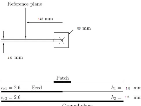
[image:2.595.319.562.71.255.2]The proposed antenna geometry is shown in fig.1.The antenna consists of stacked geometry of square patch with cross slot. A 50 ohm microstrip line is fed on substrate with dielectric constant Ɛr 2.6 having thickness h1 and h2 respectively. The side length of square patch is taken to be 66 mm. The dimension of slot 1 is 20x2mm2 and dimension of slot 2 is12x2mm2..The centered cross slots on square patch excites two orthogonal resonant modes with 90° phase shift thus provides circular polarization. The height of two substrates taken as 1.6mm. The proposed antenna shows dual band operation for L and S bands that shows its application in GNSS and Radio navigation at desired resonant frequencies. Another design is proposed using single substrate and shape of patch changes from square to circular having radius 40 mm. is shown in fig. 2. Both the designs are compared and analyzed.
Fig. 1 Design of proposed Antenna 1
Fig. 2 Design of proposed Antenna 2
Fig. 3 Proximity coupled antenna model for square patch
[image:2.595.58.286.288.453.2]Fig. 4 Single fed antenna model for circular patch
Table 1. Parameters
Parameters Square
patch
Circular patch
Length(ground) 148mm 148mm Width(ground) 148mm 148mm Side length(patch) 66mm -
Radius(patch) - 33.31mm(40mm for obtaining same resonant frequencies) Slot1(thickness) 2mm 2mm
Slot1(length) 20mm 20mm
Slot2(thickness) 2mm 2mm
antenna we calculated side length of patch as
Side length of square patch = 2*(radius of circular patch)
3.
STIMULATED RESULT ANALYSIS
Ansoft HFSS 14 is used to simulate both the designs for desired applications and result analysis has been carried out for different parameters such as return loss, VSWR, gain and radiation pattern.
3.1
Return Loss
This is the most important parameter to calculate the input and output response of signal source. The response of magnitude of S11 versus frequency curve clearly explains return loss as shown in fig.5 and fig. 6 for antenna1 and 2 respectively. Both antennas resonate at two resonant frequencies 1.26GHz and 2.56 GHz. These frequencies provides the application for GNSS and Radio navigation.
1.00 1.25 1.50 1.75 2.00 2.25 2.50 2.75 Freq [GHz] -30.00 -25.00 -20.00 -15.00 -10.00 -5.00 0.00 d B(S (W a ve Po rt 1 ,W a ve Po rt 1 )) HFSSDesign2
XY Plot 14 ANSOFT
m1
m2 Curve Info dB(S(WavePort1,WavePort1)) Setup1 : Sw eep1 Name X Y
m1 1.2634 -17.8913 m2 2.5627 -26.6858
Fig. 5 Return loss for Antenna 1
1.00 1.25 1.50 1.75 2.00 2.25 2.50 2.75 Freq [GHz] -30.00 -25.00 -20.00 -15.00 -10.00 -5.00 0.00 d B(S (W a ve Po rt 1 ,W a ve Po rt 1 ))
single substrate circular slot1
XY Plot 16 ANSOFT
[image:3.595.315.556.72.424.2]Curve Info dB(S(WavePort1,WavePort1)) Setup1 : Sw eep1
Fig. 6 Return loss for Antenna 2
3.2
VSWR
VSWR stands for voltage standing wave ratio. The VSWR of both antennas lies in the range between 1 and 2 and is shown in fig.7 & 8.
1.00 1.25 1.50 1.75 2.00 2.25 2.50 2.75 Freq [GHz] 0.00 10.00 20.00 30.00 40.00 50.00 d B(V SW R (W a ve Po rt 1 )) Curve Info dB(VSWR(WavePort1)) Setup1 : Sw eep1 b='66mm'
dB(VSWR(WavePort1)) Setup1 : Sw eep1 b='67mm'
Fig. 7 VSWR for Antenna 1
.
1.00 1.25 1.50 1.75 2.00 2.25 2.50 2.75
Freq [GHz] 0.00 10.00 20.00 30.00 40.00 50.00 d B(V SW R (W a ve Po rt 1 ))
single substrate circular slot1
XY Plot 19 ANSOFT
Curve Info dB(VSWR(WavePort1)) Setup1 : Sw eep1
Fig. 8 VSWR for Antenna 2
3.3
Gain
The centered cross slots in both the models having different shape of patches provide circular polarization.
Fig. 9 Gain for Antenna 1
[image:3.595.56.293.271.632.2]Fig. 10 Gain for antenna 2
For antenna 2 having single substrate with circular patch provides 7.685 dB as shown in fig 10.
3.4
Radiation Pattern
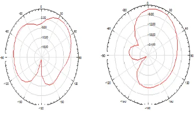
The radiation patterns of both the antennas show its circular polarization for LHCP and RHCP antenna and the graphs show both its E plane and H plane by taking phi =0° and phi=90° all the graphs that shows its circular polarization by inserting cross slots in the patches are shown in figures 11,12, 13 & 14.
Fig. 11 E-plane for LHCP and H-plane for LHCP
[image:4.595.324.523.72.170.2]Antenna 1
Fig. 12 E plane for RHCP and H plane for RHCP
[image:4.595.64.260.391.508.2]Antenna 1
Fig. 13 E plane for LHCP and H plane for LHCP
Antenna 2.
Fig. 14 E plane for RHCP and H plane for RHCP
Antenna 2
The proposed antennas resonate at two frequencies 1.26GHz and 2.56 GHz that are applicable for GNSSS application and Radio navigation application. Thus both the proposed designs show its dual band operation and are circularly polarized.
Table 2. Return loss and gain of proposed antenna 1 and 2
S. No. Antenna Frequency
(GHz)
Return loss
Gain
1 Square
patch using double substrate
1.26GHz and 2.56GHz
-17.89dB and -26.68dB
7.874dB
2 Circular patch using single substrate
1.26GHz and 2.65GHz
-17.45dB and -25.32dB
7.685dB
4.
CONCLUSION
After analyzing the results of two different configurations circular patch using single substrate with cross slots yields better result in terms of return loss, gain and size miniaturization without using any size reduction technique as compared to square patch using double substrate with cross slots. The proposed antennas are applicable for L and S bands.
5.
REFERENCES
[image:4.595.302.557.437.576.2]propagation letters, vol.11, 2012.
[3] Nasimuddin, Karu Esselle, and A.K. Verma, “High gain compact circularly polarized microstrip antenna,” IEEE TENCON 2005, November 21-24, 2005, Melbourne. [4] Halim Boutayeb, Tarek Djerafi, and Ke Wu, “Gain
enhancement of a circularly polarized microstrip patch antenna surrounded by a circular mushroom-like substrate,” Proceedings of the 40th European Microwave conference, September 28-30, 2010, Paris, France. [5] Shing-Lung StevenYang, Ahmed A. Kishk, and
Kai-Fong Lee, “wideband circularly polarized L-shaped slot antenna,” Proceedings of iWAT, 2008, Chiba, Japan. [6] A. Pomsathit, C. Benjangkaprasert, N. Anantrasirichai,
V. Chutchavong, and T. Wakabayashi, “Circularly polarized right angle slot antennas for WLAN of IEEE 802.11b/g,” International symposium on communications and information technologies, (ISCIT 2008).
[7] Nasimuddin, Xianming Qing, and Zhi Ning Chen, “Compact asymmetric-slit microstrip antennas for circular polarization,” IEEE transactions on antennas and propagation, vol.59, No.1, January 2011.
[8] Jeen- Sheen Row, Tsung-Yu Lee, and Mu-Yi Chen, “Circularly polarized ring slot antenna fed by a V-shaped
propagation, Issue:99, 2011.
[9] Jia-Yi Sze, and Wei-Hung Chen, “Axial-ratio-bandwidth enhancement of a microstrip-line-fed circularly polarized annular-ring slot antenna,” IEEE transactions on antennas and propagation, vol.59, No.7, July 2011. [10] Nasimuddin, Zhi Ning Chen, and Xianming Qing, “A
compact circularly polarized cross-shaped slotted microstip antenna” IEEE transactions on antennas and propagation, vol.60, No.3, March 2012.
[11]Dr. G. Manoj Someswar, T.P. Surya Chandra Rao, and Dhanunjaya Rao. Chigurukota, “Global navigation satellite systems and their applications,” International journal of software and web sciences (IJSWS), December-2012-february, 2013, pp.17-23.
[12]Shenzheng Zuo, Luyao Shi, and Encheng Wang, “The design of a dual-band antenna for GPS/Beidou applications,” International journal of computer science issues (IJCSI), vol.10, Issue4, No.2, July 2013.
[13]Hisao Iwasaki, “A circularly polarized small-size microstrip antenna with a cross slot,” IEEE transactions on antennas and propagation, vol.44, No.10, October 1996.