Parallel Processing Technique for High Speed Object
Recognition
Rasiq S.M
School of Technology and Applied Sciences, Mahatma Gandhi University
Regional Centre, Edappally, Kochi-682024
India
S. Krishnakumar
School of Technology and Applied Sciences, Mahatma Gandhi University
Regional Centre, Edappally, Kochi-682024
India
ABSTRACT
In this work, we introduce a novel method for recognizing a discriminative object at a very high speed. The system is based on self learning high speed parallel processing devices. The system processes video streams at speed of 1000 frames per second or more. For high speed object recognition using sequential computing from an image of a video having thousands of frames per second and each image frame consists of thousands of pixels, we need very much time for executing complicated algorithms. In the traditional way of computing and recognizing systems are very time consuming compared to our system because the traditional systems use sequential computation for recognizing, with some complicated functions. If we use other types of parallel processors like ANN for processing each pixel or group of pixels, those systems need programming and giving data to such large number of processors are practically difficult. Here we have used a self learning parallel processor device which is made for doing some kinds of particular jobs. This parallel processing devices are easy to manipulate and can be trained simultaneously. It contains memory for storing data comparators for comparing with previously stored memory etc. Training as well as functioning are in real time even if the system process thousands of image frames per second.
General Terms
Object recognition, Image Processing
Keywords
Object recognition, Parallel processors, self learning.
1.
INTRODUCTION
Traditional ways of computing for recognizing an object use sequential computing. Those are time consuming systems [2,4] and cannot be used for very high speed computing and object recognition systems. Those systems convert an object region in an image to boundary [1] lines and curves [6] and finally use some complicated analysis like line detection algorithm for recognizing the object [2]. These processes are very time consuming. Here we have designed a device, which can be used for parallel processing, for fast computing and fast object recognition systems. This device is easy to manipulate. It learns to compute from its previously learned memory. For parallel processing a large number of such devices can be used.
All devices which are working parallel can be simultaneously learned from an experience. After certain number of learning or experiences a device can produce an output high (1) or low (0) from an input variable. The device
checks whether the particular variable value is in a particular range and produce the output. The range has an upper limit and a lower limit. If the particular variable has a value within the range then the device output will be high. Learning is the function of finding this upper limit and lower limit for a particular variable.
The self learning equipment like Perceptron needs more number of learning sets than our device and it is complicated. The Perceptron manages more than one variable. It will also produce an output high or low depending on the inputs, weights and threshold value [5]. Here the input may be affected by some noises. And these are used only for some specific applications. Our device processes a single variable and it learns to compute the output by the help of a trainer which will tell the device whether the output is high or low for a particular variable value. In this work we introduce another device which can be called as an Encoder Trainer (ET). This ET will train the processor for computing the lower limit and upper limit of a variable used for some particular applications.
Here we can see the simple diagram of the device and its working, the device learning algorithm, the gray level recognition, color recognition methods, calculation of object identity and its related ET and its working.
2.
PROCESSOR AND METHOD
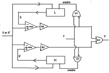
A processor will learn to produce an output from its previous memory. Learning is the function of finding the values of lower limit k and upper limit k`, if the inputs X(n)and the corresponding out puts Y(n) are given for learning. Figure 1 shows the diagram of a self learning device or processor. We can use op-amps as comparators, A1 and A2 as proceeding amplifiers, L and H as high resolution analog memory locations [3] These L and H are used for storing the values of lower limit k and the upper limit k`. We have used three AND gates in which two of them (G1 and G2) are one input bubbled. These G1 and G2 AND gates are used for generating memory enable signals for L and H locations. When memory enable signal becomes high, the corresponding analog memory locations stores the value of Xm at that time if and only if the value of Ym is high in that training period. Here Xm and Ym are the element of a training set.
[image:2.595.137.510.71.321.2]
Fig 1: Self learning device
2.1. Learning Algorithm (RK algorithm)
1. initialize k=Xmax and k`=X min
2. mth training step:check whether Ym=0 or 1
If Ym =1 and k ≥ Xm store Xm to the location L
If Ym=1 and k` ≤ Xm store Xm to the location H
3. Go to step 2 until the learning process is completed
4. decrease k= k- ∆X and increase k`= k`+∆X
End
2.2 Example for a learning procedure
Here it is given an example of finding the values of k an k` from a set.
Example : Find k and k’ for the set
[image:2.595.49.280.595.754.2]{(8,1),(6,1),(4,0),(14,0),(12,1)}, Let k=15 and k`=0;
Table 1. Learnig of the device
Trail (n) X(n) Y(n) k k`
1 8 1 8 8
2 6 1 6 8
3 4 0 6 8
By observing the above table we can understand the learning procedure from the 5 trails. Figure 2 shows a representation of the trained device.
Fig 2: A representation of trained device
The device gives most accurate output if it is trained with correct set of X,Ypairs. If one of the elements Ym in a pair in the training set is not correct and variable Xm is beyond the expected limits k and k`, then the pair in that set is not suited for learning. And if one of the elements Ym in a pair in the training set is not correct and variable Xm is within the expected limits k and k`, then the pair in that training set may be suited
We may be confused that why the machine knowledge (k and k`) are in a range. The answer is simple that almost all the variables are affected by some errors or noises, getting the exact values are difficult. That is why we use this kind of device.
3.
GRAY LEVEL RECOGNITION
Fig 3: Basic color matching device
Using the training set of a primary color, the device will learn to identify the intensity of that primary color. After training the device, it will produce an output high when that particular primary color intensity value is given as its input. Then the three devices representing three primary colors are given to an AND gate as shown in figure 3 and its output will give whether the color matches or does not match. Consider the image is a matrix having m number of rows and n number of columns then we need 3mn number of devices. After training is completed if we are giving an input image with the same colored object then all the outputs of the AND gates representing the object become high.
5.
CALCULATION OF OBJECT
IDENTITY
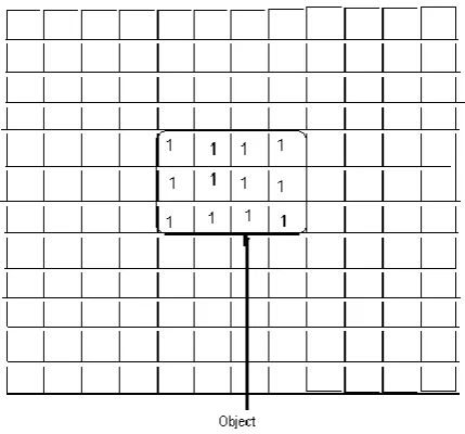
After the previously explained processing the image will become in binary form. The object in an image will be appeared as a region having the values 1 and rest of them will be 0. In other words in the matrix having m rows and n columns in which all the values of the pixels within the object boundary will be high and the rest of them will be low or zero as shown in figure 4.
[image:3.595.58.273.451.651.2]For each value of row we can use an ET and a Processor and similarly for each value of column.
Fig 4: Object in a binary image
5.1. Encoder Trainer
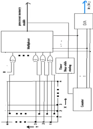
Figure 5 shows the diagram of an Encoder Trainer which consists m number of X-OR gates (here we are explaining about an ET in the x direction if it is in the y direction number of X-OR gates will be n). Suppose we consider the ( n-1)th column then we need m number of X-OR gates. The two inputs of each X-OR gate are connected to the corresponding row elements of that image matrix as shown in the figure 5. The first and second elements of that column are connected to X-OR gate one, the Second and third elements of that column are connected to X-OR gate 2. Similarly all the elements of that column are connected to corresponding X-OR gates.
The outputs of all X-OR gates of the column are connected to an m input multiplexer, a counter will help the multiplexer to scan the entire X-OR gate outputs in that column. When the multiplexer output becomes high the processor memory enable signal helps to store the value of D/A converter output to the corresponding memory of that processor.
When a change from 0 to 1 is detected, corresponding X-OR gate output becomes high, then the corresponding least value is stored in the corresponding Processor’s memory location L known as k. When a change from 1 to 0 is detected corresponding highest value is stored in the corresponding Processor’s memory location H known as k`.
5.2. Creating object identity
[image:4.595.146.472.72.523.2]
Fig 5:Encoder Trainer
y directions. After applying these ETs we will get (x1,x2) from the x direction and (y1,y2) from the y direction. Now we can calculate the object identity
Identity =(x2-x1)/(y2-y1)
This object identity can be used as a parameter for recognizing the Object
The shape, length, breadth and color of an object in an image can be represented using the memories of the Processors and each segment can be analyzed. Here we use a simple method for recognizing the object
surroundings. The image should be taken from a scene with almost uniform light intensity. Here we have used an object with a single gray level intensity or a single colored object. So we need to teach only one device for gray level object and only three devices for a colored object. The trained device or devices will pass the gray level intensity or color to all other devices in the image matrix. If the object is rotated with an angle then the learned object will be different compared to the original rotated object. In this case we have to use some additional methods for recognizing the object.
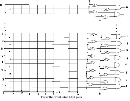
Fig 6: The circuit using X-OR gates
If we consider the ET, we have used simple X-OR gates, those inputs are connected to the outputs of parallel Processors or to the binary image matrix. This method we used for simply computing the object identity. This is because when we compute x2-x1 or y2-y1 the result must not be 0. If a line appears in x or y direction the above problem can be occurred. The actual method of X-OR gate arrangement is shown in figure 6. Here we have used two X-OR gates connected with each row element of the matrix (considering x direction only) as shown in figure 6. The outputs of X-OR gates representing an element in the matrix are connected to an AND gate. Then AND gate output will give whether the particular element is 0 or 1.
7.
CONCLUSION
The color, length, breadth and shape of an object can be analyzed using this method and also recognized easily. It can be used for identifying regions having a particular texture in an image. It is very easy to manipulate. A large number of devices are required for image processing application for parallel processing. But for some application related to artificial intelligence and machine learning, a few number of devices are only needed. It can also be used as a logical gate whose output will be high for the input in a range and its output will be low for the input outside the range. The noises in a binary image can be eliminated by using our processors if we use a system with a two input AND gate and two processors.
8.
REFERENCES
[1] B. Catanzaro, B. S. amd N. Sundaram, Y. Lee, M. Murphy, and K. Keutzer. (2009) Efficient, high-quality image contour detection.In ICCV.
[2] Christoph H. Lampert, Jan Peters (2009), Active Structured Learning for High- Speed \ Object
Detection, Max Planck Institute for Biological Cybernetics Tubingen, Germany
[3] Chris Diorio, Sunit Mahajan, Paul Hasler, Bradley Minch, Carver Mead, (1995), A High- Resolution
Nonvolatile Analog Memory Cell, California Institute of Technology Pasadena, California 91125 (818)
395-6996
[4] Joachims, T., Finley, T., Yu, C.N.:,(2009), Cutting-plane training of structural SVMs.Machine Learning
[5] Radford M. Neal (1995), Bayesian Learning For Neural Network, Department of Computer Science, University of Toronto