Dual Band Dual Polarized Slot Cut modified Circular
Microstrip Antenna
Amit A. Deshmukh
EXTC, DJSCOE Vile – Parle (W), Mumbai, India
Sagar Makwana
EXTC, DJSCOE Vile – Parle (W), Mumbai, India
Vijay Jain
EXTC, DJSCOE Vile – Parle (W), Mumbai, India
ABSTRACT
A new broadband and dual band circular slot cut modified circular microstrip antenna is analyzed and proposed. The parametric study to analyze the effects of circular slot which realizes broader bandwidth is presented. The circular slot creates two additional resonant modes near the fundamental TM11 mode resonance frequency of the equivalent circular
patch and yields bandwidth of 202 MHz (8%). The polarization of the two modes which realizes broadband response was found to be orthogonal, which leads to the principal plane variations over the bandwidth. Further by using this concept, a circular slot cut dual band and dual polarized circular slot cut circular microstrip antenna in 1000 MHz frequency band is proposed. The proposed antenna yields dual frequency response with orthogonal polarization and variable frequency ratio with bandwidth of 2% at the dual frequencies.
Keywords
Circular Microstrip Antenna, Broadband microstrip antenna, Dual band microstrip antenna, Dual polarization, Circular slot, Higher order mode
1.
INTRODUCTION
More commonly broadband and dual band microstrip antenna (MSA) is realized by cutting the slot of different shapes like, U-slot, V-slot, rectangular and toothbrush shaped slot at an appropriate position on the edges or inside the patch [1 – 9]. The slot is said to introduce a resonant mode near the fundamental mode resonance frequency of the patch when its length either equals half wave or quarter wave in length. In recent study on slot cut MSAs, it was observed that slot does not introduce any additional mode but reduces the resonance frequency of higher order orthogonal mode of the patch and along with fundamental patch mode yields broadband or dual band response [10 – 12]. In these slot cut MSAs, a single polarization is realized over the complete bandwidth (BW) or at the dual frequencies when the polarization of radiated field due to patch mode and the mode introduced by slot, are in the same direction. The dual polarization is realized when the field due to two modes are orthogonal to each other.More commonly dual polarized MSAs are realized by cutting the slot in the patch center and further by feeding it along the diagonal axis [1]. By selecting appropriate ratio of patch and slot dimensions, a variable frequency ratio has been realized [1]. With respect to the fundamental mode of operation, compact MSA is realized by cutting the slot inside the patch or by placing the shorting post along the zero field line in the patch [13]. The slot lengthens the surface current length and reduces its resonance frequency for given patch size whereas shorting technique converts half wave length resonator into a quarter wavelength resonator. The conventional half wave length resonator shows broadside radiation pattern with lower cross polarization levels. Due to an un-symmetrical field distribution around the patch edges, shorted and slot cut
MSAs shows radiation pattern with higher cross polar levels. In application like mobile communication, since the polarization of incoming wave is not known, MSAs with higher cross polar levels will be useful. Recently a new circular slot cut circular MSA (CMSA) and key shaped slot cut CMSA is reported [14]. The equivalent CMSA operates at frequency of 2520 MHz and 5120 MHz which corresponds to the TM11 and TM02 modes of circular patch. At each of the
above mode, CMSA gives lower BW of 1 to 2%. To enhance the BW, a circular slot was cut inside and towards the periphery of the patch and another smaller radius circular patch was placed inside the slot. This configuration operates at 2470 and 5830 MHz with BW of 3.45 % and 3.03%, respectively at the two frequencies. To improve this BW at dual frequencies, key shaped slot cut MSA was proposed [14].
In this paper, first an analysis of reported circular slot cut CMSA is presented. The behavior of slot cut CMSA around its fundamental TM11 mode (2000 to 3000 MHz) is studied.
Around that frequency range/mode, a broadband response with the formation of loop inside the VSWR = 2 circle in the smith chart is observed, which shows BW of 202 MHz (8%). The radiation pattern over the BW was found to be in broadside direction. However, a variation in E-plane direction from = 900
to 00, is noticed over the BW. Therefore a detail analysis to study the effect of circular slot in CMSA, is presented. It was observed that, circular slot creates two resonant modes (degenerates fundamental mode into two modes) around the TM11 mode frequency of CMSA. The
parametric study for variations in circular slot dimensions and its position is presented. When the circular slot is placed towards the perimeter of the patch the first of dual frequencies reduces whereas second frequency increases thereby realizing smaller frequency ratio of 1.0 to 0.9. However when the circular slot is placed closer to the center of patch, both the frequencies reduces and realizes variable frequency ratio in the same range. For different slot position, at first frequency, the surface currents maximum is aligned along = 900
whereas at second frequency they are aligned along = 00. Therefore at first frequency, E-plane is aligned along = 900
, whereas at second frequency it is aligned along = 00. Thus the slot cut CMSA will realize dual band dual polarized or broadband dual polarized response. Further in 1000 MHz frequency band and using glass epoxy substrate (r = 4.3, h =
improve upon the gain, suspended configurations of slot cut CMSAs can be used, which will also increase the BW. The radiation pattern was measured in minimum reflection surroundings with required minimum far field distance between reference antenna and antenna under test [16].
2.
CIRCULAR SLOT CUT CMSA
The reported circular slot cut CMSA is shown in Fig. 1(a, b). The patch is fabricated on FR4 substrate having parameters, r
= 4.4, h = 0.159 cm, tan = 0.025. For CMSA, measured resonant frequencies for observed TM11 and TM02 modes are,
2520 and 5120 MHz, respectively as shown in Fig. 1(c) [14]. Since the BW at dual frequencies is smaller, an offset circular slot is cut inside the patch, as shown in Fig. 1(a, b) [14]. The radius of the inner and outer circle is, 0.2 and 0.4 cm, respectively. The observed dual frequencies for the slot cut CMSA are, 2470 and 5830 MHz, with nearly 3% BW, at the two frequencies, as shown in Fig. 1(c) [14]. The return loss (S11) plot for slot cut CMSA shows proximity of two resonant
modes towards the higher frequency range. To analyze the configuration, for xf = 0.7 and yf = 0.6 cm, slot cut CMSA is
simulated using IE3D software in 2000 to 6000 MHz frequency range and its resonance curve plot is shown in Fig. 1(d). The resonance curve shows proximity of two resonant modes around 2500 MHz and 5500 MHz. These frequencies are closer to TM11 and TM02 mode resonance frequencies of
the equivalent CMSA. To study the response of slot cut CMSA around its TM11 mode frequency, the MSA is
simulated in the frequency range of 2000 to 3000 MHz and its input impedance plot is shown in Fig. 1(e). The plot shows the formation of loop inside the VSWR = 2 circle, indicating the broadband response. The realized BW is from 2407 to 2607 MHz (202 MHz (8%)). This broader BW is realized due to the two adjacent modes present near the TM11 mode frequency of
equivalent CMSA as observed in the resonance curve plot. The surface current distributions at the two modes (peaks) are shown in Fig. 2(a, b). The distributions at both the frequencies are similar to the TM11 mode of CMSA and they show nearly
half wavelength variations along half of the patch perimeter. However at first frequency, maximum of surface currents is aligned along = 900 whereas it is along = 00
, at second frequency. This leads to the variation in E-plane direction from = 900
to 00, over the VSWR BW. The surface current contribution on the inner smaller circular patch was found to be minimum. Since radius of smaller circular patch is smaller, its resonance frequency does not lie near the resonance frequency of TM11 mode of CMSA. Therefore without the
inner circular patch, slot cut CMSA shows similar result in 2000 to 3000 MHz frequency range, to that shown in Fig. 1(e).
Fig. 1 (a) Top and (b) side views, (c) measured return loss plots [14], simulated (d) resonance curve and (e) input
impedance plots for circular slot cut CMSA
To analyze the configuration for the excitation of two orthogonal modes, parametric study is carried out. For x = 1.0 cm and r = 0.5 cm, slot cut CMSA is simulated for different feed point locations, as shown in Fig. 2(c) and there resonance curve plots in 2000 to 3000 MHz frequency range are shown in Fig. 2(d).
[image:2.595.317.543.66.560.2]
Fig. 2 (a, b) Surface current distribution at dual frequencies, (c) circular slot cut CMSA and its (d) resonance curve plots for different feed point locations
When the feed point is located either along x or y-axis i.e. at feed point location ‘A’ or ‘C’, a single mode is observed in the resonance curve plot since the feed point is located at the minimum impedance location of the corresponding orthogonal mode. Further the effects of variations in circular slot radius and its position on the dual frequencies are studied and they are plotted in Fig. 3(a, b). The surface current distributions at second frequency for r = 0.4 cm and x = 0.5 and 1.0 cm, are shown in Fig. 3(c, d). Also the resonance curve plots for varying slot position and slot radius for given feed point location are shown in Fig. 4(a, b). For smaller slot radius (r < 0.4 cm), when circular slot is placed near the patch centre (x < 0.5 cm), two distinct modes are not observed in the resonance curve plot. This is because smaller slot radius does not create an orthogonal unequal path lengths or degenerates TM11 mode
into two orthogonal modes. For smaller slot radius, this is observed when the slot is placed more towards patch edge as it increases un-symmetry in the structure. When the slot is placed close to the patch centre, it increases surface current lengths at both the modes which reduce their frequencies. However when the slot is placed close to the patch edge, first of the dual frequency reduces whereas second frequency increases. As observed from the surface current distributions at second mode, when the slot is placed more towards the
patch edge, surface currents does not start from the patch edge, which reduces the effective patch radius, that increases its resonance frequency. The first frequency reduces due to an increase in surface current lengths due to the slot. For both the values of slot position, variable frequency ratio in the range of 1 to 0.9 is observed. As observed from Fig. 4(a, b), when the slot radius is higher, both the frequencies reduce. Whereas when slot position is changed (i.e. from x = 0.5 to 1.0 cm), for given slot radius, first frequency remains nearly constant whereas second frequency increases.
Fig. 3 (a, b) Variation in dual frequencies and their ratio for different circular slot positions and radius, and (c, d) surface current distributions at second frequency for
circular slot cut CMSA
[image:3.595.54.282.73.465.2] [image:3.595.316.544.183.629.2]The measured dual frequencies and BW’s are, 2345 and 2601 MHz and 78 and 102 MHz, respectively.
Fig. 4 Resonance curve plots for (a) variations in slot radius, x = 0.5 cm and (b) position, r = 0.5 cm and (c) optimized dual band response, (____) simulated, (___ ___)
measured for slot cut CMSA
Further by using the above concept, dual band and dual polarized circular slot cut CMSA is designed in 1000 MHz frequency band. Using glass epoxy substrate (r = 4.3, h =
0.16 cm, tan = 0.02) the patch radius for TM11 mode
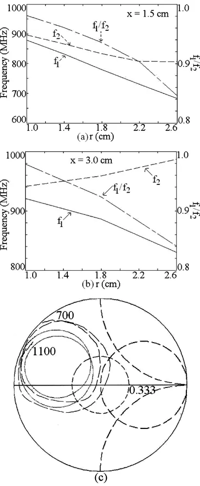
frequency to be around 1000 MHz, is calculated to be 4.5 cm. The slot is cut inside the patch and for different values of slot position (x) and its radius (r), the variation in dual frequency is shown in Fig. 5(a, b). The similar behavior to that observed in above reported slot cut CMSA is present. Further for x = 3.0 cm and r = 1.4 cm, the optimized dual band and dual polarized response is realized as shown in Fig. 5(c).
Fig. 5 (a, b) Variation in dual frequency and their ratio for different circular slot positions and radius and (c) optimized dual band response for slot cut CMSA in 1000 MHz frequency band, (_____) simulated, (___ ___) measured
The simulated dual frequencies and BW’s are, 825 and 980 MHz and 12 and 18 MHz, respectively. The patch was fabricated using glass epoxy substrate of dimension 20 cm side length and the experiment was carried out using R & S vector network analyzer. The measured dual frequencies and BW is 836 and 975 MHz and 11 and 19 MHz, respectively as shown in Fig. 5(c). The fabricated prototype of the configuration is shown in Fig. 6(a). The radiation pattern at dual frequencies is shown in Fig. 6(b, c). The pattern is in the broadside direction with E-plane aligned along = 900
at first frequency and along = 00 at second frequency. Since the
[image:4.595.56.272.104.583.2]
Fig. 6 (a) Fabricated prototype and (b, c) radiation pattern at dual frequencies for dual band circular slot cut CMSA
3.
CONSLUSIONS
The dual band and dual polarized circular slot cut CMSA in 2000 – 3000 MHz frequency band is analyzed and proposed. In circular slot cut CMSA, for larger slot radius or when slot is placed more towards the CMSA edges, slot degenerates TM11 mode of CMSA into two orthogonal modes. Further for
different slot radius and their positions it realizes dual band dual polarized response with variable frequency ratio in the range of 1 to 0.9. The slot cut dual band dual polarized CMSA in 1000 MHz frequency band is proposed. The proposed CMSA yields nearly 2% BW at the dual frequencies with variable frequency ratio of 1 to 0.8.
4.
REFERENCES
[1] Wong, K. L. 2002. Compact and Broadband Microstrip Antennas, John Wiley & sons, Inc., New York, USA
[2] Huynh, T., and Lee, K. F. 1995. Layer Single-Patch Wideband Microstrip Antenna, Electronics Letters, vol. 31, no. 16, (August 1995), 1310-1312.
[3] Guo, Y. X., Luk, K. M., Lee, K. F., and Chow, Y. L. 1998. Double U-slot Rectangular Patch Antenna, Electronics Letters, vol. 34, (1998), 1805 – 1806
[4] Sharma, S. K., and Shafai, L. 2009. Performance of a Novel -Shaped Microstrip Patch Antenna with Wide Bandwidth, IEEE Antennas & Wireless Propagation Letters, vol. 8, (2009), 468 –471.
[5] Lee, K. F., Yang, S. L. S., Kishk, A. A., and Luk, K. M. 2010. The Versatile U-slot Patch, IEEE Antennas & Propagation Magazine, vol. 52, no. 1, (February 2010), 71 – 88.
[6] Wong, K. L., and Hsu, W. H. 2001. A Broadband Rectangular Patch Antenna with a Pair of wide slits, IEEE Transactions on Antennas & Propagation, Vol. 49, No. 9, (September 2001), 1345 – 1347.
[7] Yang, F., Zhang, X., Yc, X., and Sammi, Y. R. 2001. Wide-band E-shaped patch antennas for wireless communication, IEEE Transactions on Antennas & Propagation, vol. 49, no. 7, (July 2001), 1094 – 1100.
[8] Lee, K. F., Yang, S. L. S., and Kishk, A. A. 2008. Dual and Multi-band U-slot patch Antennas, IEEE Antennas and wireless Propagation Letters, vol. 7, (2008), 645 – 647.
[9] Vedaprabhu, B., and Vinoy, K. J. 2010. An Integrated Wideband Multifunctional Antenna using a Microstrip patch with two U-slots”, Progress In Electromagnetic Research B, vol. 22, (2010), 221 – 235.
[10]Deshmukh, Amit A., Joshi, Apurva A., and Tirodkar, T., Broadband slot cut gap-coupled proximity fed E-shaped Microstrip Antenna, International Journal of Computer Application, vol. 68, no. 17, April 2013, 15 – 18
[11]Deshmukh, A. A., Ray, K. P., and Kadam, A. 2013. Analysis of slot cut Broadband and Dual band Rectangular Microstrip Antennas, IETE Journal of Research, vol. 59, no. 3, (May – June 2013), 193 – 200.
[12]Deshmukh, A. A., and Ray, K. P. 2013. Analysis of Broadband -shaped Microstrip Antennas, IEEE Magazine on Antennas and Propagation, vol. 55, no. 2, (June 2013), 107– 123.
[13]Kumar, G., and Ray, K. P. 2003, Broadband Microstrip Antennas, First Edition, USA, Artech House
[14]Garima, Bhatnagar, D., Saini, J. S., and Saxena, V. K. 2010. Modified circular patch antenna with key shape slot for wireless communication systems, International Journal of Microwave and Optical Technology, vol. 5, no. 6, (November 2010), 396 – 401.
[15]IE3D 12.1, 2004. Zeland Software, Freemont, USA
[image:5.595.55.282.81.532.2]![Fig. 1 (a) Top and (b) side views, (c) measured return loss plots [14], simulated (d) resonance curve and (e) input impedance plots for circular slot cut CMSA](https://thumb-us.123doks.com/thumbv2/123dok_us/8056723.775319/2.595.317.543.66.560/views-measured-return-simulated-resonance-input-impedance-circular.webp)