www.ijsrp.org
Highly Improved Handoff Performance in
MIMO-Enabled CBTC System
C. Binu Jeya Schafftar
Applied electronics [email protected]
Abstract - Communication-Based Train Control (CBTC) system is an automated train control system to ensure the safe operation of rail vehicles using data communication. Bidirectional wireless train–ground communications is used to transfer control data between trains and wayside equipment. Wireless local area network (WLAN) based CBTC has impact on train control performance while taking handoff decisions. This may leads to communication interrupt and long latency. Inorder to minimize the handoff latency and to improve the performance, a handoff scheme in CBTC system based on WLANs with multiple-input-multiple-output is proposed. In this channel estimation errors and the tradeoff between MIMO multiplexing gain and diversity gain are considered in making handoff decisions. Handoff decisions and physical layer parameters are optimised to improve the train control performance in CBTC systems. The handoff problem is formulated as a partially observable Markov decision process (POMDP), and the optimal handoff policy can be derived to minimize the handoff latency. The handoff decision and physical layer parameters adaptation problem is formulated as a stochastic control process. Simulation result shows that the proposed approach can significantly improve the control performance in CBTC systems.
Index Terms - CBTC, Train Control, multiple-input– multiple-output (MIMO), wireless local area network (WLAN)
I. INTRODUCTION
WITH the rapid population explosion, there is a strong desire around the world to improve the rail transit speed and capacity. Being a key subsystem in rail transit systems, communications-based train control (CBTC) is an automated train control system using high capacity and bidirectional train-ground communications to ensure the safe operation of rail vehicles. It can improve the utilization of railway network infrastructure and enhance the level of safety and service offered to customers. CBTC is a modern successor in a traditional railway signaling system using track circuits, interlocking, and signals.
Train-ground communication is one of the key technologies in CBTC systems. Wireless networks, such as Global System for Mobile communications - Railway (GSM-R) and Wireless Local Area Networks (WLANs),
are commonly used to provide bidirectional train- ground communications. For urban mass transit systems, IEEE
802.11a/b/g based WLANs are a better choice due to the available commercial-off-the-shelf equipment and the philosophy of open standards and interoperability. There are several WLAN-based CBTC systems deployed around the world, such as Las Vegas Monorail from Alcatel and Beijing Metro Line 10 from siemens.
Building a control system over wireless networks is a challenging task. Ideally, the data transfer over the communication links should be accurate, timely, and reliable. However, a communication network inevitably introduces random packet delay and losses. The problem is more pronounced in CBTC systems, where the communication environment is complex between a fast moving train and ground. Particularly, when a train moves away from the coverage of a WLAN access point (AP) and enters the coverage of another AP along the railway, a handoff procedure occurs. This handoff process may result in communication interrupt and long latency, which could severely affect train control performance, train operation efficiency, and the utilization of railway network infrastructure.
The communication availability and latency requirements in CBTC systems are very stringent. Trains and ground equipment communicate with each other and expect a response within a time constraint after sending a request. Long communication latency, which leads to delayed response, could cause train derailment, collision, or even catastrophic loss of life and/or assets. Therefore, minimizing train–ground communication latency is aspired, so that rapid responses can be facilitated while a train is moving at high speed.
Several schemes have been proposed to decrease WLAN handoff latency. Most of previous works in optimizing WLAN handoffs focus on making more efficient scanning process, since it is shown that over 90% of the time in the handoff process is spent in the scanning stage. A SyncScan technique is proposed in [13], in which appropriate time synchronization is required between APs and clients. A topology-inferencing technique in both clients and APs is proposed in [14] to improve the scanning process.
The schemes previously proposed work for single radio mobile clients requires coordination/cooperation between APs and mobile clients, which may make it difficult to implement them in CBTC systems. There are also some schemes using multiradio in mobile clients trying to reduce the WLAN handoff latency. Adya et al. [1] proposed a protocol to allow multiradio mobile nodes in a mesh network to potentially establish two separate wireless links between a pair of nodes. This work primarily focuses on improving the efficiency of wireless mesh networks, which is different from the CBTC systems.
www.ijsrp.org multiplexing capability to mitigate interferences. It is shown in
[15] that the Transmission Control Protocol performs better with a more reliable link provided by the MIMO diversity gain, whereas the spatial multiplexing scheme outperforms in the high-SNR regions. There are also intermediate MIMO working modes, where we can simultaneously achieve part of the diversity gain and part of multiplexing gain. Lee et al. [7] studied the optimal tradeoff between MIMO diversity gain and multiplexing gain in ad-hoc networks.
A handoff scheme in CBTC systems based on WLANs with multiple-input–multiple-output (MIMO) technologies is proposed to improve the handoff latency performance. MIMO-enabled WLANs have been increasing in popularity due to the fact that multiple antennas can achieve higher data rate, compared to conventional single-antenna systems. The recent IEEE 802.11n standard aims to significantly improve the physical link data rate up to 600 Mb/s with MIMO technologies. Although the data rate has been improved in MIMO-enabled WLANs, the handoff latency performance may not be satisfactory when MIMO-enable WLANs are used in high-speed CBTC systems. In particular, the tradeoff between MIMO diversity gain and multiplexing gain [17], which is a physical-layer design parameter, should be carefully designed according to the fast-changing signal-to-noise ratios (SNRs) from successive APs when a train is moving at high speed.
MIMO system in CBTC environments, have distinct characteristics, such as high speed mobility with frequent handoffs and stringent latency requirements. In addition, most WLAN handoff decision algorithms are based on the quality of the received signals from successive Aps. However, when a train is moving at high speed, the channel state derived from channel estimations may not be accurate, which will result in wrong handoff decisions. This will further increase the communication latency in WLAN-based CBTC. Channel estimation errors and MIMO working mode is considered to improve the handoff latency performance in MIMO-enabled CBTC systems. The distinct features of this work are given here.
1) CBTC train–ground communication system based on MIMO-enabled WLANs is proposed.
2) The dynamic wireless channel is modeled as a finite state Markov process. With channel estimation errors, the channel state cannot be accurately observed. 3) Based on the inaccurate channel state information, the
station adapter (SA) on a train makes handoff decisions and adapts physical-layer MIMO parameters to minimize the communication latency. 4) The handoff decision and physical-layer parameter
[image:2.595.305.517.607.724.2]adaptation problem is formulated as a partially observable Markov decision process (POMDP).
Fig. 1. Communication based train control system
5) Extensive simulation results based on real field channel measurements are presented. It is illustrated that the proposed scheme can significantly improve the handoff latency performance in CBTC systems.
II. CBTC TRAIN–GROUND COMMUNICATION BASED ON MIMO-ENABLED WLANS
In this section, we first present an overview of CBTC and its train–ground communication systems. We then present the proposed CBTC train–ground communication system based on MIMO-enabled WLANs.
A. Overview of CBTC Train–Ground Communication Systems
CBTC system consists of five subsystems. They are Automatic Train Supervision (ATS) subsystem, Automatic Train Operation (ATO) subsystem, Automatic TrainProtection (ATP) subsystem, Zone Controller (ZC) subsystem, and train ground communication subsystem. Central control automatic train supervision (ATS) permits the dispatcher to monitor the entire system and issue commands manually or automatically, to change the routing, performance, and station dwell times of trains according to an operation schedule.
The ATS may have a finer resolution as to where CBTC trains are located at all times. The ATS station is a means of monitoring and controlling the system at a specific wayside location (most commonly, a station location). In other words the ATS subsystemmakes timetables for each train; it sets the trip time between two stations. The ATP subsystem on the train calculates the real time braking curve according to the newest received MA. Based on the trip time given by ATSand other performance indices, such as energy savings, and passengers comfort, the ATO subsystem derives an optimized guidance trajectory.
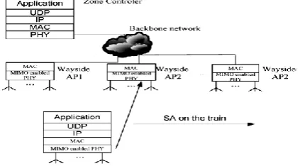
[image:2.595.39.242.626.781.2]Fig. 1 shows a simple CBTC with a WLAN-based train– ground communication system. In CBTC systems, continuous bidirectional wireless communications between each station adapter (SA) on the trainand the ground access point (AP) are adopted instead of thetraditional fixed-block track circuit. The railway line is usually divided into areas. Each area is under the control of a ZC and has its own wireless transmission system. The identity, location, direction and velocity of each train
Fig .2. CBTC system based on MIMO-enabled WLAN
www.ijsrp.org location of all the trains in its area at all times. Based on the
locations of all thetrains and other obstacles alone the railway, the ZC transmits a Movement Authority (MA) to each train. An MA of a train is the zone from the tail of the train to the obstacle in front of the train.
Once the train velocity reaches the target velocity on the service braking curve or emergency curve, the ATP subsystem will start service or emergency braking prior to ATO subsystem to protect the train from traveling out of its MA.
Train–ground communication systems are primarily designed to connect each component of CBTC systems: ZCs, APs along railways, and train aboard equipment. A basic configuration of a WLAN-based train–ground communication system is shown in Fig. 1. Following the philosophy of open standards and interoperability [12], the backbone network of the train–ground communication system includes Ethernet switches and fibre-optic cabling that is based on the IEEE 802.3 standard. The wireless portions of the train–ground communication system, which consist of APs along the railway and SAs on the train, are based on the IEEE 802.11 series standard. When a train moves between successive APs, the received SNR rapidly changes. The communication latency will be a serious problem when the SA is in deep fading. Furthermore, when a train moves away from the coverage of an AP and enters the coverage of another AP along the railway, the handoff procedure may result in long latency. To minimize the latency, we present a train–ground communication system based on MIMO-enabled WLANs to improve the handoff performance.
B. Proposed CBTC Train–Ground Communication System Based on MIMO-Enable WLANs
Fig. 2 describes the proposed CBTC train–ground communication system based on MIMO-enable WLANs. The application-layer data packets being encapsulated in the User Datagram Protocol are then transferred between trains and wayside equipment using Internet Protocol and WLANs with IEEE 802.11 MAC and MIMO-enabled physical layer
A critical issue in the aforementioned system is the handoff decision policy (i.e., when to perform a handoff) and the corresponding physical-layer parameter adaptation policy (i.e., the tradeoff between MIMO diversity gain and multiplexing gain). In high-speed environments, wireless channels are dynamically changing. If these policies are not carefully designed, long communication latency may occur, which will significantly affect the performance of CBTC systems. Therefore, an efficient handoff decision policy and a physical-layer parameter adaptation policy are needed to decide at which time to trigger handoff and what physical-layer parameters should be used.
III. COMMUNICATION LATENCY OPTIMIZATION IN THE PROPOSED CBTC TRAIN–GROUND
COMMUNICATION SYSTEM
A. Communication Latency in MIMO-Enabled WLANs
The diversity gain and spatial multiplexing gain can be realized with a MIMO system, and there is a fundamental tradeoff between them [17]. For each spatial multiplexing gain r, the best diversity gain d∗(r) is the supremum of the diversity gain achieved over all schemes. With long enough block lengths, the optimal multiplexing-diversity tradeoff d∗(r) is
given by the piecewise-linear function connecting the points(r, d∗(r)) for r = 0, 1..., min ( ) [17].
∗ ( ) ( )( ) (1)
Where and are the number of transmit and receive antennas, respectively, and they map to the number of wayside AP and train SA antennas. Optimal tradeoff performance can be achieved with a family of carefully designed codes. If the wireless link from the train SA to the wayside AP has an average SNR γ, with a multiplexing gain r, the link data rate C(r) and Bit Error Probability BER(r) can be approximated as
( ) ∗ ( ) (2) ( ) ∗ ( ) (3)
Where and are positive constants for different coding schemes, and the multiplexing gain r and diversity gain d(r) satisfy the optimal tradeoff equation. Given the link BER, the corresponding Frame Error Rate (FER) is derived as
( ) where
is the MAC layer frame length in bits.
First, calculate the communication latency when no handoff happens. Consider carrier-sense multiple access with collision avoidance (CSMA/CA) as the MAC method since it is most commonly used in WLAN systems. In CSMA/CA systems, a window-based backoff mechanism is used such that a node that is willing to transmit will sense the medium first, and if the medium is not free, it will uniformly choose a backoff time at random from the interval [0, CW + 1], where CW is the contention window and the initial value is equal to . CW will be doubled if the subsequent transmission attempt fails until it reaches .
There are two causes of packet transmission failure in WLANs. One is the packet collision where two nodes simultaneously transmit. The other one is the channel error, where a packet is received without packet collisions and is corrupted due to low SNR. Although the SA on a train is in the common communication coverage area of two APs, it can only associate with one of the two APs. Furthermore, there is only one SA in each AP cell in CBTC systems, which is due to the fact that trains must keep a distance that is far enough between each other to guarantee safety. There is no other competing SA within each AP cell. Therefore, the packet delay is mainly due to packet retransmissions caused by packet losses but not the packet collision.
With packet loss caused only by channel error, when a packet is transmitted n times in the MAC layer, the corresponding packet delay in ( )CSMA/CA systems can be calculated as follows:
( ) ( )
( )
( )
(4)
www.ijsrp.org of the data, and is the time needed to transmit a data
frame, which is given by
( ) (5)
With the n times packet delay ( ) he average communication latency with maximum retransmission time R is given by
( ) ∗ ( ) ( ( ) ∗ ( ) ( ) ∗ ( )(6)
The average MAC-layer packet transmission delay is dependent on the physical-layer transmission data rate and the retransmission time. Given a certain SNR, a higher multiplexing gain r will give a higher capacity link, which contributes to the time needed to transmit a data frame. However, the diversity gain d will decrease with the increase in multiplexing gain. The corresponding FER increase will lead to an increasing transmission time that, ultimately, brings in more overhead. Therefore, one of the aims in our communication latency model is to find the optimal multiplexing gain r to minimize the latency when no handoff happens, and the optimization problem is given as ∗ ( ) (7)
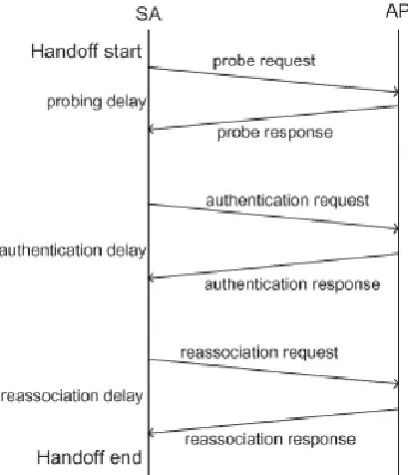
In the following, the communication latency model when a handoff happens is derived. Fig. 3 shows us a simple view of the 802.11 WLAN handoff procedures, which is followed by most 802.11 mobile stations [11]. As shown in the figure, the handoff procedure can be divided into three steps, i.e., probing (also referred to as scanning), authentication, and reassociation. Six packets are transmitted between the SA and AP before the handoff ends, and the average time needed to finish the handoff is approximately ∗ ( ) , where
( ) is the communication latency given above and is the processing time in the AP and SA before they send new packets.
[image:4.595.51.236.557.772.2]The SA will continue to periodically send probe packets with the period until it gets in to
Fig .3. Handoff procedure
the authentication phase. If any one of the authentication and reassociation packets is lost, the handoff procedure will start from the beginning. It will take a long time before the SA starts over again and that time is referred as .
The average handoff latency is then derived as
( ) ∗ ( ) ∗
[ ∗ ( ) ] [ ( ) ] ∗ [ ∗
( ) [ ( ) ] ∗
{( ) ∗ [ ∗ ( ) ]
[ ( ) ] ∗ [ ∗ ( )
]} (8)
Where PLR is the packet loss rate, which is dependent on the FER and retransmission time n. Assume that the handoff failure happens at most once in the above equation due to the fact that the probability that two successive handoffs both fail is very small. Another aim in our communication latency model is to find the optimal multiplexing gain to minimize the latency when a handoff happens.
∗
( ) (9)
B. Stochastic Formulation of the Proposed CBTC Train–Ground Communication System
Markov decision process (MDP) provides a mathematical framework for modeling decision making in situations where outcomes are partly random and partly under the control of a decision maker. In the proposed CBTC train–ground communication system, the SA on the train makes handoff decisions at specific time instances according to the current state s(t), and the system moves into a new state based on the current state s(t), as well as the chosen decision a(t). Given s (t) and a(t), the next state is conditionally independent of all previous states and actions. This Markov property of state transition process makes it possible to model the optimization problem as an MDP. Furthermore, in CBTC systems, due to channel sensing and channel state information errors, the system state cannot be directly observed. As a result, the optimization problem as a POMDP is formulated, in which it is assumed that the system dynamics are determined by an MDP. However, the underlying state can only be observed inaccurately or with some probabilities.
A Partially Observable Markov Decision Process (POMDP) is a generalization of a Markov Process Decision. A POMDP models an agent decision process in which it is assumed that the system dynamics are determined by an MDP, but the agent cannot directly observe the underlying state. Instead, it must maintain a probability distribution over the set of possible states, based on a set of observations and observation probabilities, and the underlying MDP.
www.ijsrp.org Based on the observation, the system jointly considers the
multiplexing gain r in the physical layer and decides whether to make a handoff action to minimize the communication latency. To obtain the optimal solution, it is necessary to identify the states, actions, state transition probability, observation model, and reward functions.
1)Action, State, and Observation: In CBTC train–ground communication system, the SA on the train first has to decide whether the connection should use the current chosen AP or connect to the next AP. (We assume that the SA on the train will not be in the coverage of three successive APs.) Second, the multiplexing gain in the physical layer should be decided. We assign every AP along the railway with a distinct number. Let M be the AP that covers the SA; then, the other one is M + 1. The current composite action a (t) ∈ A is denoted by
( ) ( ) ( ) (10) Where (t) is the handoff action, and (t) is the multiplexing gain action (0 < (t) < min ( , )). (t) = M + 1 means handoff to the next AP; (t) = M means stay in the old AP. The current composite state s(t) ∈ S is given as
( ) ( ) ( ) ( ) (11)
Where ( )and ( )are the measured SNR from two successive APs, respectively; and ξ (t) is the currently used AP. ξ(t) ∈ {M,M + 1} because the currently used AP is completely decided by the current action.
The composite observation θ (t) ∈ Θ is defined as
( ) { ̂ ( ) ̂ ( ) ̂( )} (12)
Where ̂ ( ) ̂ ( ) ̂( ) are the observation of
( ) ( ) ( ) respectively; and they have the same space as the state space.
2) State Transition Model and Observation Model: Given the current state S (t) = ( ) ( ) ( ) , the current observation ( ) { ̂ ( ) ̂ ( ) ̂( )} and the chosen action a(t) the probability function of the next state ( )
( ) ( ) ( ) is given by
P (s (t + 1) |s (t), (θ (t), a (t))) = P [ (t + 1) | (t)]
∗ P [ (t + 1) | (t)] ∗ P [ξ (t+1) |ξ (t), a (t)] (13) where P[ (t + 1) | (t)] and P[ (t + 1)| (t)] are the channel state transition probabilities for the two wireless links, respectively; and P[ξ(t+1)|ξ(t), a(t)] is the currently used AP
transition probability. The channel state transition probabilities for the two wireless links can be derived from the received SNRs measured in field tests. The AP that will be used after the decision epoch is dependent on the current handoff decision action. Given the current handoff decision action (t), the AP that will be used in the next epoch must be (t). Therefore, the currently used AP transition probability is simply derived as,
P [ξ (t+1) |ξ (t), (θ (t), a (t))] ={ ( ) ( )( ) ( )
(14) Given the channel estimation errors, the SA is not able to have full knowledge of the channel information. Assume that the channel estimation error has a Gaussian distribution with zero mean and variance. At a particular time epoch, the observed channel gain is
̂ (15)
Where ̂ is the actual channel gain and ω is a Gaussian random variable with zero mean and variance. The receiver then quantizes
3) Reward Function: As shown in Fig. 2, after the SA on the train establishes a wireless link to a new AP, the new AP needs to tell the ZC that the SA is associated with it. Afterward, the packets sent from the ZC to the SA will go through the new AP, instead of the old AP. Therefore, aside from the communication latency caused by the WLAN, there is an extra latency caused by the wired part between the ZC and the APs, such as propagation, processing, and queuing delays. The total end-to-end communication latency should be the sum of all these delays in both the wireless part and the wired part.
The latency in the wireless part when a handoff occurs is . The latency in the wired part depends on several factors in real systems, such as the distance between the ZC and the APs, the size of the network, the processing power of network nodes, etc. Parameter K to represent the latency caused in the wired part when a handoff occurs. Different values of K are used to evaluate the performance of the proposed scheme. Considering the current link latency the reward function is defined as
{ ( ⁄ ( ( )) ) ( ) ( ) ( ⁄ ( ( ))) ( ) ( )
(16) TABLE 1
www.ijsrp.org IV. SIMULATION RESULTS AND DISCUSSIONS
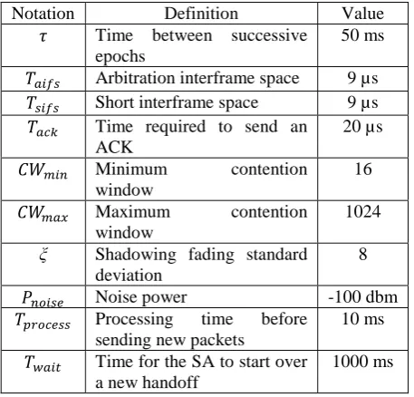
NS2.29 simulator is used for the simulations. Consider a simulation scenario with a train moving between successive APs. The average distance between two successive APs is 600 m. The train speed is 80 km/h. The main parameters used in the simulations are shown in Table I. Simulation examples are used to illustrate the performance of the proposed scheme. First the FSMC model obtained from real field test data is discussed. The performance improvement of the POMDP optimization algorithm is given next. The simulation results shows that the proposed method reduce the delay while taking handoff by observing the channel information and received signal to noise ratio.
A. Received SNR
In the field test, the SNR from two successive Aps is measured. An AirMagnet Wi-Fi analyser is used as the SNR measurement instrument. The measurement instrument’s antenna was put in the same place as the SA’s antenna on the train. The measurement instrument travelled with the train when the train was in real operation. The measurement sampling rate was set as 1000 Hz. The measured SNR from two successive APs is shown in Fig. 4.
B. Performance Improvement
Compare the POMDP policy performance in the proposed MIMO-enabled CBTC system with the performance in traditional CBTC systems without MIMO technology. The communication latency in our proposed MIMO-enabled CBTC system is always better than the system without MIMO technology. This is because the MIMO diversity gain decreases the packet loss probability during the handoff procedure, and the MIMO multiplexing gain decreases the time needed to transmit a packet. The decreased packet loss probability and packet transmission time both contribute to the communication latency performance improvement.
[image:6.595.30.259.59.278.2]
Fig. 4. Received SNRs from two APs
Fig .5. Performance improvement compared to MIMO disabled system
V. CONCLUSION
Train-ground communication is one of the key technologies in CBTC systems. The handoff process in WLANs has significant impacts on the train control performance in CBTC systems. CBTC systems have stringent requirements for wireless communication latency. The dynamic radio propagation environment and frequent handoffs can cause significant communication latency in WLAN-based CBTC. In the proposed method, a CBTC train–ground communication system based on MIMO-enabled WLANs has been presented. Wireless channel estimation errors and MIMO working mode was considered to improve the handoff latency performance in CBTC. Based on the inaccurate channel state information, handoff decisions have been made, and physical-layer MIMO parameters have been adapted to minimize the communication latency. The problem has been modelled as a POMDP.POMDP policy always gives the better average handoff latency compared with other policies. Simulation results have been presented to show that the proposed POMDP-based policy can significantly decrease the average handoff latency in CBTC systems.
ACKNOWLEDGMENT
I would like to thank the reviewers for their detailed reviews and constructive comments, which have helped improve the quality of this paper.
REFERENCES
[1] Adya.A, Bahl.P, Padhye.J, Wolman.A, and Zhou.L, (2004) “A multiradio unification protocol for IEEE 802.11 wireless networks,” in Proc. BROADNETS, San Jose, USA, pp. 344–354.
[2] Dong.H, Ning.B, Cai.B and Hou.Z, (2010) “Automatic train control system development and simulation for high-speed railways,” IEEE Circuits Syst. Mag. vol. 10, no. 2.
[3] Fitzmaurice. M , (2005) “Use of wireless local area networks in rail and urban Transit environments,”
Notation Definition Value
Time between successive epochs
50 ms
Arbitration interframe space 9 µs Short interframe space 9 µs Time required to send an
ACK
20 µs
Minimum contention window
16
Maximum contention window
1024
ξ Shadowing fading standard deviation
8
Noise power -100 dbm Processing time before
sending new packets
10 ms
Time for the SA to start over a new handoff
[image:6.595.304.511.85.265.2]www.ijsrp.org Transp. Res. Rec., J .Transp. Res. Board, vol. 1916,
no. 1, pp. 42–46.
[4] Khan.M and Zhou.X, (2010) “Stochastic optimization model and solution algorithm for robust double-track train-timetabling problem,”IEEE Trans. Intell Transp. Syst., vol. 11, no. 1.
[5] Krishnamurthy.V and Djonin.D, (2007) “Structured threshold policies for dynamic sensor scheduling: A partially observed Markov decision process approach,” IEEE Trans. Signal Process., vol. 55, no.10, pp.4938–4957.
[6] Lee. J, Chiang. M and Calderbank. A. R, (2006) “Price-based distributed algorithms for rate-reliability tradeoff in network utility maximization,” IEEE J. Sel. Areas Commun., vol. 24, no. 5.
[7] Li.L, Zhang.H, Wang.X, Lu.W, and Mu.Z, (2011) “Urban transit coordination using an artificial transportation system,”IEEE Trans Intell.Transp Syst., vol. 12, no. 2, pp. 374–383.
[8] Lin.Y and Wong.V, (2009) “Cross-layer design of MIMO-enabled WLANs with network utility maximization,”IEEE Trans. Veh. Technol., vol. 58, no. 5, pp. 2 443–2456.
[9] Liu.J, Yu.F.R, Lung.C.H, and Tang.H, (2009) “Optimal combined intrusion detection and biometric-based continuous authentication in high security mobile ad hoc networks,” IEEE Trans. Wireless Commun. vol. 8, no. 2.
[10] Mishra.A, Shin.M, and Arbaugh.W,(2003) “An empirical analysis of the IEEE 802.11 MAC layer handoff process,” SIGCOMM Comput. Commun. Rev., vol. 33.
[11] Pascoe.R.D and Eichorn.T.N, (2009) “What is communication- based train control”, IEEE Veh. Technol. Mag., vol. 4.
[12] Ramani.I and Ramani.I, (2005) “Syncscan: Practical fast handoff for 802.11 infrastructure networks,” in Proc. IEEE INFOCOM, Seoul, Korea, pp. 675–684.
[13] Shin.M, Mishra.A, and ArbaughW.A, (2004) “Improving the latency of 802.11 hand-offs using neighbour graphs,” in Proc. MobiSys, Boston, USA, pp. 70–83.
[14] Toledo.A.L and Wang.X, (2006) “TCP performance over wireless MIMO channels with ARQ and packet combining,”IEEE Trans. Mobile Comput., vol. 5, no. 3, pp. 208–223.
[15] Wei.Y, Yu.F.R, and Song.M, (2010) “Distributed optimal relay selection in wireless cooperative networks with finite-state Markov channels,” IEEE Trans.Veh.Technol., vol.59, no. 5, pp. 2149–2158. [16] Zheng.L and Tse.D.N.C, (2003) “Diversity and
multiplexing: A fundamental tradeoff in multiple-antenna channels,” IEEE Trans. Inf. Theory, vol. 49, pp. 1073–1096.