Fuzzy Logic Control for harvesting maximum
power from PV solar based SEPIC Converter
Goshwe, N.Y, Igwue G.A and Kureve, D.T.*
Department of Electrical and Electronics Engineering, Federal University of Agriculture, Makurdi, Nigeria.
*Email: kurevedt@gmail.com
DOI: 10.29322/IJSRP.8.12.2018.p84108
http://dx.doi.org/10.29322/IJSRP.8.12.2018.p84108
Abstract: This paper presents a maximum power point tracking (MPPT) control that makes use of fuzzy logic for switching a single-ended primary-inductor (SEPIC) converter for harvesting power from a photovoltaic (PV) system. The proposed FLC MPPT is presented at varying irradiances of 1000, 900, 700 and 500 W/m2 and varying temperatures of 30,
25, 20 and 18oC respectively. The SEPIC converter has a
voltage output of 58.70 V for 1000 W/m2 at 18oC and the PV
panel has power output at 407.7 W over 1000 W/m2 and 18oC.
The fuzzy controller for the SEPIC MPPT scheme shows good current transition and keeps the voltage constant within the acceptable limits, in variable temperatures and irradiances.
Keywords: Fuzzy Logic Controller, SEPIC, Photovoltaic (PV) system, Irradiance and Temperature
I.INTRODUCTION
Alternative renewable Energy has received great attention and importance today due to its sustainability as well as how friendly they are to the environment. The energy demand in the world especially Nigeria has greatly increased due to the industrial revolution. Photovoltaic (PV) solar panel is a simple and reliable technology which directly convertsenergy from the sun (solar energy) into electricity for home and industrial utilization [2-5].
Maximum power can be obtained from photovoltaic panels, for use by using maximum power point tracking (MPPT) controller [3]. Various approaches have been reported to implement MPPTsuch as perturb andobserve (P&O) method, the incremental conductance method (INC), constant voltage methodand short-circuit current method [4-6]. Using this method the maximum power point can be found for specified solar irradiation and temperature condition but they displayoscillatory behavior around the maximum power point under normal operating conditions. Moreover the system will notrespond quickly to rapid changes in temperature or irradiance.
On the other hand the conventional PI controllers are fixed gain feedback controllers. Therefore they cannot compensate the parameter variations in the process and cannot adapt
changes in the environment. PI-controlled system is less responsive to real and relatively fast alterations in state and so the system will be slower to reach the set point. Recently intelligent based schemes have been introduced [7-10]. Among the intelligent based methods fuzzy logic has its own merits such that the algorithm is easy to form. The shape of the membership function of the fuzzy logic controllers can be adjusted such that the gap between theoperation point and maximum power point can be optimized. A SEPIC dc-dc converter provides constant dc voltage which has a duty cycle that is controlled by the FLC MPPT controller [8-11]. Among all the available converters, SEPIC has the merits of non-inverting polarity, easy to drive the switch with low input current pulsating for high precise MPPT that makes its characteristics suitable for the low power PV based charger system. SEPIC converter can raise the output voltage to the suitable range, the supply an isolation route to isolate the input and the output terminals after terminating the charging. But this circuit has two disadvantages; one is low efficiency and the other is it needs two inductors [10].
This paper presents, a control technique using fuzzy logic control (FLC) which is used in tracking MPP of the PV solar panels of a SEPIC dc-dc converter thereby extracting maximum power from the PV solar module under varying solar temperature and irradiation using MATLAB / SIMULINK are presented.
2. METHODOLOGY
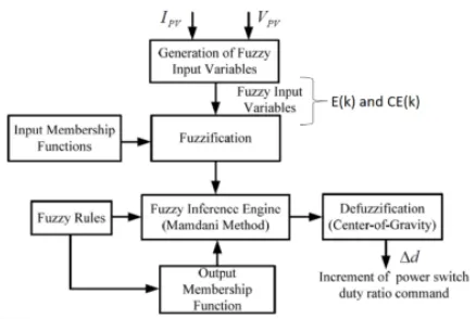
Figure 1: The Block diagram of PV solar SEPIC converter using FLC MPPT
2.1 Photovoltaic Module
A solar PV cell basically is a p-n semiconductor junction. Whenever certain amount of light is being exposed on the solar panel, then a DC current varies linearly with the solar PV irradiance. The equivalent electrical circuit of an ideal PV cell can be considered as a current source parallel with a diode. The I-V characteristic of the solar PV module for varying irradiances (1000, 900, 700 and 500 W/m2) at constant
[image:2.612.327.546.77.224.2]temperature of 25 degrees is as presented in Figure 2.
Figure 2: PV characteristic curve for varying irradiance
2.2 Fuzzy Logic (FLC) Controller
The variables are identified and the set values of each linguistic variable are determined. The input variables of the FLC controller are the input variables of the fuzzy logic controller are the slope of the power variation, E (k) and the slope, CE (k) of the PV panel. The output of the FLC controller is the duty cycle of the PWM signal controls the converter switching gate. The triangular membership functions is used for the FLC. The fuzzy logic control system can be generalized presented in Figure 3.
Figure 3: The FLC MPPT design
The input variables of the fuzzy logic controller are the slope of the power variation and the change of the slope defined as in Equations (1) and (2).
𝐸𝐸(𝑘𝑘) =�𝑃𝑃𝑝𝑝𝑝𝑝𝑉𝑉 (𝑘𝑘)−𝑃𝑃𝑝𝑝𝑝𝑝(𝑘𝑘−1)
𝑝𝑝𝑝𝑝(𝑘𝑘)−𝑉𝑉𝑝𝑝𝑝𝑝(𝑘𝑘−1)� (1)
𝐶𝐶𝐸𝐸(𝑘𝑘) =𝐸𝐸(𝑘𝑘)− 𝐸𝐸(𝑘𝑘 −1) (2)
A seven-term fuzzy sets, Negative big (NB), Negative medium (NM), Negative small (NS), zero (ZZ), Positive small (PS), Positive medium (PM), and Positive big (PB) are defined to describe each linguistic variable term. Each linguistic term associated with a set linguistic variable has a degree of membership that ranges from zero to one both inclusive as shown in table 1.
Table 1: FLC Rule table
CE/E NB NM NS ZZ PS PM PB NB NB NB NB NB NM NS ZZ NM NB NB NB NM NS ZZ NS NS NB NB NM NS ZZ PS PM ZZ NB NM NS ZZ PS PM PB PS NM NS ZZ PS PM PB PB PM NS ZZ PS PM PB PB PB PB ZZ PS PM PB PB PB PB
2.3 SEPIC Converter
The SEPIC DC-DC converter consist of two inductors (L1 and
L2), three capacitors (C1and Co), a diode (D) and switch (Q)
which is typically a transistor such as MOSFET.
L1
Q
VIN Vo
D C1
[image:2.612.46.298.335.470.2]Figure 4: The circuit diagram of the SMPS.
The SEPIC converter in Figure 4 is in Continuous Conduction Mode (CCM) therefore, current in the inductor L1is always
greater than zero.
3.0 Simulation Study
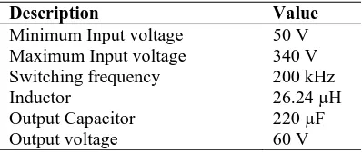
[image:3.612.317.578.242.357.2]The simulation of the PV solar FLC MPPT based SEPIC converter is performed in MATLAB/Simulink using the following SEPIC converter and PV solar module parameters presented in table 2 and 3.
Table 2: SEPIC DC-DC Converter design specifications
Description Value
Minimum Input voltage 50 V Maximum Input voltage 340 V Switching frequency 200 kHz
Inductor 26.24 µH
Output Capacitor 220 µF
Output voltage 60 V
Table 3: solar panel specificationsSunpower E20 400 watt solar panels SPR-E
Parameters Specifications
Power output 400 W
Open circuit voltage (Voc) 85.3 V Short circuit current (Isc) 6.43 A Voltage at maximum power (Vmpp) 72.9 V Current at maximum power (Impp) 5.97 A
Module size 36 cells
[image:3.612.40.239.243.327.2]The simulation is performed using the Simulink environment of MATLAB software and the circuit is as presented in Figure 6
Figure 5: Simulink model of the Fuzzy logic MPPT controller PV solar SEPIC Converter
Figure 6: Simulink model of the Fuzzy logic controller MPPT
4.0 RESULTS
This chapter presents output obtained from the simulations of analysis done in chapter three.
Figure 7: Output Voltage of SEPIC converter using FLC MPPT for different Irradiances and temperature
The summary of Figure 7 is as presented in Table 4
Table 4: SEPIC converter voltage under varying Irradiance and Temperature for FLC MPPT
S/N Voltage (V)
Irrad (W/m2)
Temp (oC)
Time (s)
1 57.74 58.15 58.50 58.70
1000 30 25 20 18
0.0 – 0.1 0.1 – 0.2 0.2 – 0.3 0.3 – 0.4 2 55.17 900 25 0.4 – 0.5 3 48.63 700 25 0.5 – 0.6 4 40.95 500 25 0.6 – 0.7
Figure 7 presents the output voltage of the PV solar based SEPIC converter using FLC MPPT controller. The output voltage as it relates to varying irradiance and temperature is as presented in Table 4. From table 4, it indicates that the output voltage of the converter for FLC MPPT is maximum at 57.74 V, 58.15 V, 58.50 V and 58.70 V for irradiance of 1000 W/m2,
temperature changes from 30oC, 25oC, 20oC and 18oC
respectively. At temperature of 25oC, irradiances of 900
[image:3.612.41.274.372.455.2] [image:3.612.314.520.462.577.2] [image:3.612.46.281.500.629.2]700 W/m2 and temperature of 25oC, the maximum voltage
output is 48.60 V. The irradiance of 500 W/m2, temperature of
25oC, the maximum voltage recorded is 40.94 V. Oscillations
[image:4.612.318.596.70.187.2]are not observed in the output wave form of the SEPIC converter but it is observed that at every change in temperature, there is a dip in the output voltage signal before it settles back through the action of the FLC MPPT controller.
Figure 8: PV Solar Output Voltage and varying Irradiance for FLC MPPT
Figure 9: PV Solar Output Voltage and varying Temperature for FLC MPPT
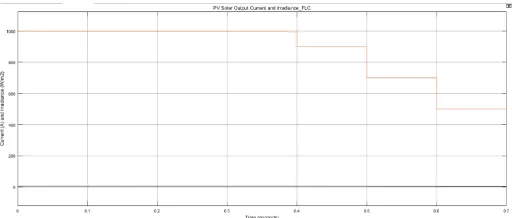
Figure 10: PV Solar Output Current and varying Irradiance for FLC MPPT
[image:4.612.46.302.188.295.2]Figure 11: PV Solar Output Current and varying Temperature for FLC MPPT
Figure 12: PV Solar Output Power and varying Irradiance for FLC MPPT
Figure 13: PV Solar Output Power and varying Temperature for FLC MPPT
The summary of Figure (s) 8 – 13 are as presented in Table 5
Table 5: PV Solar Output Voltage, Current and Power under varying Irradiance and Temperature for FLC MPPT
S/N Voltage (V)
Current (A)
Power (W)
Irrad (W/m2)
Temp (oC)
Time (s)
1 71.64 72.49 73.56 74.04
5.51 5.52 5.51 5.51
394.7 400.1 405.3 407.7
1000 30 25 20 18
[image:4.612.318.569.236.341.2] [image:4.612.45.293.341.446.2] [image:4.612.319.572.365.494.2] [image:4.612.46.302.495.604.2]Figure (s) 8 – 13 presents the PV output for voltage, current and power over varying irradiances and temperature for FLC MPPT. From table 5, and figures (s) 8 – 13, the output voltage of the PV panel using FLC MPPT in figure 8 and 9 is 71.64 V, 72.49 V, 73.56 V and 74.04 V over a constant irradiance of 1000 w/m2 and varying temperatures of 30, 25, 20 and 18
degrees respectively, at varying irradiances of 900, 700 and 500 w/m2, the temperature remains constant at 25 degrees with
the voltage at 72.54 V, 72.42 V and 72.16 V respectively. Figure (s) 10 and 11 presents the current output with varying irradiance and temperature. The Current constantly peaks at 5.51A over an irradiance of 1000 w/m2 but varying
temperature of 30, 25, 20 and 18 degrees. At varying irradiances of 900, 700 and 500 w/m2 and constant
temperature of 25 degrees, the output current is 4.94 A, 3.86 A and 2.76 A respectively. Figure (s) 12 – 13 presents the output power of the PV panel at varying irradiances and temperatures. The power output had 394.7 W, 400.1 W, 405.3 W and 407.7 W over a constant irradiance of 1000 w/m2 and
varying temperatures of 30, 25, 20 and 18 degrees respectively. At varying irradiance of 900, 700 and 500 W/m2
at constant temperature of 25 degrees, the output power is 360.1 W, 279.8 W and 199 W respectively.
5.0 CONCLUSION
A solar-PV system with a SEPIC dc-dc converter for harvesting maximum power using fuzzy logic controller has been simulated under varying solar irradiances and temperatures. The performance of the system presented no ripples or oscillations at the output voltage of the PV module. The model shows that at 1000 W/m2 PV system output power
increases with fall in cell temperature which conforms.
REFERENCES:
[1] Vrashali Jadhav and Ravindrakumar M.Nagarale, (2016). “Maximum Power Point Tracking of PV System Based on a SEPIC Converter Using Fuzzy Logic Controller”, Int. Journal of Engineering Research and Applications (www.ijera.com), Vol. 6, Issue 1, (Part -5), pp. 59 – 64
[2] MummadVeerachary, (2005). “Power tracking fornonlinear PV sources with coupled inductorSEPIC converter,” IEEE Trans, vol. 41, no.3.
[3] Theodoros L. Kottas, Yiannis S.Bourlis,Athanasios D. Karlis, (2006). “New maximum powerpoint tracking for PV arrays using Fuzzycontroller in close cooperation with Fuzzycognitive networks,” IEEE Trans vol. 21, no. 3.
[4] M. Singh and A. Chandra, (2011) ”Application of adaptive network-basedfuzzy inference system for sensorless control of PMSG-based wind turbine with nonlinear-load compensation capabilities,” IEEE Trans,Power Electronics, vol. 26, no. 1, pp. 165-175.
[5] Tsai-Fu Wu, Chien-Hsuanchang and Yu-kaiChen, (2000). “A fuzzy logic controlled single-stageconverter for PV powered lighting systemapplications,” IEEE Trans vol. 47, no. 2.
[6] HangL., S. Liu, G. Yan, B. Qu, and Z. Lu, (2011).”An improved deadbeatscheme with fuzzy controller for the grid-side three-phase PWM boostrectifier,” IEEE Trans, Power Electronics, vol. 26, no. 4, pp.1184-1191.
[7] WeiX. and H. Jing, (2010).“MPPT for PV system based on a novel fuzzycontrol strategy”, International Conference on Digital Manufacturing& Automation (ICDMA), pp. 960 – 963.
[8] Z. Cheng, H. Yang, and Y. Sun, (2010).“FPGA-based PV systems fuzzyMPPT control algorithm,” Seventh International Conference on FuzzySystems and Knowledge Discovery (FSKD), pp. 1244 – 1248.
[9] KottasT. L., Y. S. Boutalis, and A. D. Karlis, (2006). “New maximum power point tracker for PV arrays using fuzzy controller in close cooperation with fuzzy cognitive networks,”IEEE Trans, Energy Convers., vol. 21, no. 3, pp. 793–803.
[10] BouchafaaF., D. Beriber, and M. S. Boucherit, (2010). “Modeling andsimulation of a gird connected PV generation system With MPPTfuzzy logic control,” 7th International Multi-Conference on Systems,Signals and Devices (SSD), pp. 1-7.
[11] WonC. Y., D. H. Kim, S. C. Kim, W. S. Kim, and H. S. Kim, (1994). “A newmaximum power point tracker of photovoltaic arrays using fuzzycontroller,” IEEE 25th Annu, Power Electron. Spec. Conf., vol. 1, pp. 396–403.