ISSN 2250-3153
DESIGN AND TOPOLOGY OPTIMISATION OF A
STEERING KNUCKLE JOINT USING FEA
Pilla. Anitha*, V. Hari Shankar **.
*
Department of Mechanical Engg.Visakha Technical Campus, Narava
Abstract- Weight reduction is now the main issue in automobile industries. Weight reduction can be achieved primarily by the
introduction of better material, design optimization and better manufacturing processes. The weight of the vehicle is going on increasing due to additional luxurious and safety features. Steering Knuckle is one of the critical components of vehicle which links suspension, steering system, wheel hub and brake to the chassis. It undergoes varying loads subjected to different conditions, while not affecting vehicle steering performance and other desired vehicle characteristics.
This project focuses on optimization of steering knuckle targeting reducing weight as objective function with required strength, frequency and stiffness. In automotive suspension, a steering knuckle is that part which contains the wheel hub or spindle, and attaches to the suspension components. It is variously called a steering knuckle, spindle, upright or hub, as well. The wheel and tire assembly attach to the hub or spindle of the knuckle where the tire/wheel rotates while being held in a stable plane of motion by the knuckle/suspension assembly.
Here the optimisation refers to different cases in the shape optimisation and also the topology optimisation. The modeling of this project is done in Creo Parametric 2.0 and the analysis is carried out in Ansys 15.0.
Index Terms- Creo parametric 2.0, design optimization, stable plane motion, weight reduction.
I. INTRODUCTION
In automotive suspension, a steering knuckle is that part which contains the wheel hub or spindle, and attaches to the suspension components. It is variously called a steering knuckle, spindle, upright or hub, as well. The wheel and tire assembly attach to the hub or spindle of the knuckle where the tire/wheel rotates while being held in a stable plane of motion by the knuckle/suspension assembly.
The steering knuckle carries the power thrust from tie rod to the stub axle and hence it must be very strong, rigid and also as light as possible. In the case of automobile vehicle, during steering and turning the steering knuckle is subjected to compressive and tension loads and due to the wheel rotation it is also subjected to torsional load. Steering knuckle for automobile applications is typically manufactured either by forging or from casting. However, castings could have blow-holes which are detrimental from durability and fatigue points of view. The fact that forgings produce blow-hole-free and better parts gives them an advantage over cast parts.
In order to conserve natural resources and economize energy, weight reduction has been the main focus of automobile manufacturer in the present scenario. The introduction of composite materials has made it possible to reduce the weight of the steering knuckle without any reduction on load carrying capacity and stiffness. So, composite materials are now used in automobile industries to take place of metal parts.Since the composite materials have more elastic strain energy storage capacity and high strength-to-weight ratio as compared to those of steel. Composite materials offers opportunity for substantial weight saving.
II. PROBLEMIDENTIFICATION
Due to its large volume production, it is only logical that optimization of the steering knuckle for its weight or volume will result in large-scale savings. It can also achieve the objective of reducing the weight of the vehicle component, thus reducing inertia loads, reducing vehicle weight and improving vehicle performance and fuel economy.
So considering automobile development and importance of relative aspect such as fuel consumption, weight, riding quality, and handling, hence development of new material is necessary in the automobile industry.
ISSN 2250-3153
emissions and therefore, save environment. Weight can be reduced through several types of technological improvements, such as advances in materials, design and analysis methods, fabrication processes and optimization techniques, etc.There are four disciplines for optimization process:
a. Topology optimization:
It is an optimization process which gives the optimum material layout according to the design space and loading case. b. Shape optimization:
This optimization gives the optimum fillets and the optimum outer dimensions. c. Size optimization:
The aim of applying this optimization process is to obtain the optimum thickness of the component. d. Topography:
It is an advanced form of shape optimization, in which a design region is defined and a pattern of shape variable will generate the reinforcements.
III.
MODELINGOF STEERINGKNUCKLEJOINTThe modeling of the steering knuckle is done in Creo Parametric 2.0.
Introduction to Creo Parametric:
Creo Parametric is a computer graphics system for modeling various mechanical designs and for performing related design and manufacturing operations. The system uses a 3D solid modeling system as the core, and applies the feature-based, parametric modeling method. In short, Creo Parametric is a feature-based, parametric solid modeling system with many extended design and manufacturing applications.
Creo Parametric is the first commercial CAD system entirely based upon the feature-based design and parametric modeling philosophy. Today many software producers have recognized the advantage of this approach and started to shift their product onto this platform.
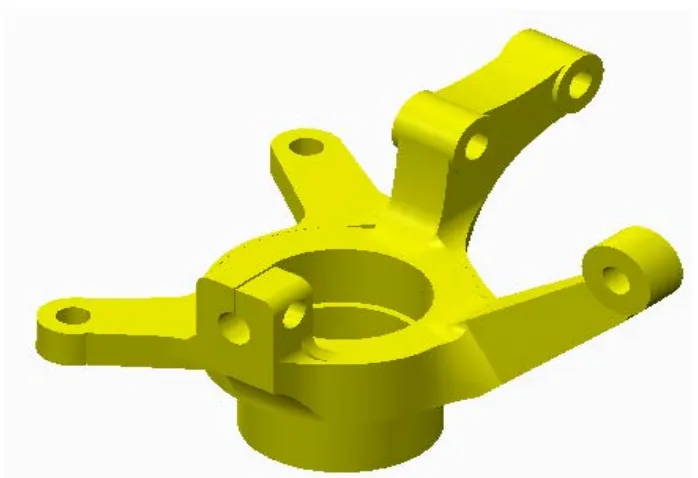
[image:2.612.132.481.460.699.2]The model is as shown in the figure 1 as shown below:
ISSN 2250-3153
Creo Parametric was designed to begin where the design engineer begins with features and design criteria. CreoParametric's cascading menus flow in an intuitive manner, providing logical choices and pre-selecting most common options, in addition to short menu descriptions and full on-line help. This makes it simple to learn and utilize even for the most casual user. Expert users employ CreoParametric's "map keys" to combine frequently used commands along with customized menus to exponentially increase their speed in use. Because Creo Parametric provides the ability to sketch directly on the solid model, feature placement is simple and accurate.
IV. ANALYSISOFSTEERINGKNUCKLEJOINT
[image:3.612.75.517.261.421.2]The analysis of the steering knuckle joint is done in Ansys 15.0 and the analysis reports are as shown below. The geometry and the mesh model in Ansys are as shown in the Fig.3 and Fig. 4 below respectively.
Fig. 3 Geometry of the steering knuckle joint Fig.4 Mesh of the steering knuckle joint
The analysis is carried out for the Cast Iron material, Aluminium material and the composite material for the steering knuckle joint.
Analysis of Steering knuckle joint:
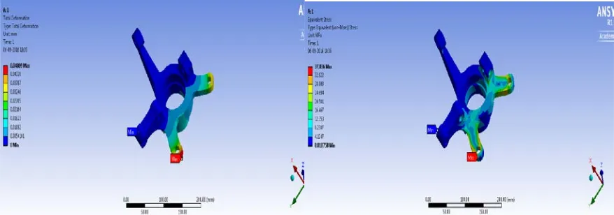
[image:3.612.72.511.533.687.2]The Boundary Conditions are given as the force of 4358N with a moment of 36375 N-mm at two supports and fixed at the three supports of the knuckle. The base material is Cast Iron. The deformation and Equivalent Stress reports for the steel steering knuckle joints are are as shown in the Fig. 5 and Fig. 6 respectively.
ISSN 2250-3153
[image:4.612.77.541.95.258.2]The deformation and Equivalent Stress reports for the first optimisationsteering knuckle joints are are as shown in the Fig. 7 and Fig. 8 respectively.
Fig. 7 Deformation of the 1st opt.steering knuckle joint Fig.8 Equivalent Stress of the 1st optsteering knuckle joint
[image:4.612.75.535.341.513.2]Also the analysis is carried out for the knuckle joint which consists of different shape optimisations. The deformation of and the Equivalent Stress reports for the last optimisedsteering knuckle joint are shown in the Fig. 9 and Fig. 10 respectively.
Fig. 9 Deformation of the opt.steering knuckle joint Fig.10 Equivalent Stress of the opt.steering knuckle joint
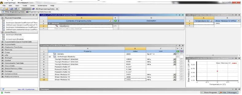
The Glass Epoxy properties are as shown in the Fig. 11
[image:4.612.128.522.568.723.2]ISSN 2250-3153
V. RESULTSANDDISCUSSION
The analysis of Steel Steering knuckle joint with the composite steering knuckle joint is done. The shape optimization and material optimization is carried out in Ansys 15.0. The results for the steering knuckle for various considerations are as shown below:
Optimisation
Base model 1 2 3 4TOTAL
DEFORMATION (mm) 0.04869 0.05583 0.06079 0.058858 0.048036
STRAIN 0.00034 0.000456 0.000448 0.000453 0.000324
STRESS (MPa) 37.036 50.023 47.337 45.249 36.424
The results for the optimized material consideration are as shown below:
RESULTS STRESS
(MPa) STRAIN
TOTAL DEFORMATION
(mm)
Optimised material with
weight (kgs)
1 53.81 0.00076 0.090 0.8755
2 76.12 0.00085 0.072 0.6321
VI. CONCLUSION
This project work involves the aim to reduce the weight of the steering knuckle joint while keeping the stress within the safe limits. Thus from the first results table it is very clear that the fourth model gives us optimized results i.e. less stress value and also less weight. The model is then analyzed Cast Iron and is optimized under different cases of material adding and material reduction.Then the optimized model is analysed for different materials such as Aluminum alloy and S- Glass Epoxy composite.The results table clearly indicate that there is a significant amount of weight reduction when we use S-Glass Epoxy material. The stress values are within the safe limits of their respective material properties.
REFERENCES
[1] Purushottam Dumbre, Prof A.K.Mishra, V.S.Aher, Swapnil S. Kulkarni, “Structural Analysis Of Steering Knuckle For Weight Reduction”, International Journal of Advanced Engineering Research and Studies, Int. J. Adv. Engg. Res. Studies/III/III/April-June, 2014/86-86
[2] Kiran S.Bhokare, G.M.Kakandikar, Swapnil S. Kulkarni, “Predicting the Fatigue of Steering Knuckle Arm of a Sport Utility Vehicle While Deploying Analytical Techniques Using CAE”, International Journal of Scientific Research and Management Studies (IJSRMS), Volume 1 Issue 11, pg: 372-381
ISSN 2250-3153
[4] Eshaan Ayyar, Isaac de Souza, Aditya Pravin, Sanket Tambe, Aqleem Siddiqui & Nitin Gurav, “Selection, Modification and Analysis of Suspension System for an All-Terrain Vehicle”, ISSN : 2319 – 3182, Volume-2, Issue-4, 2013
[5] Wan Mansor Wan Muhamad, Endra Sujatmika, Hisham Hamid, & Faris Tarlochan, “Design Improvement of Steering Knuckle Component Using Shape Optimization”, International Journal of Advanced Computer Science, Vol. 2, No. 2, pp. 65-69, Feb. 2012.
[6] Nassir S. Al-Arifi, Abu S. Zamani, and Jalaluddin Khan, “Billet Optimization for Steering Knuckle Using Taguchi Methodology”, International Journal of Computer Theory and Engineering, Vol. 3, No. 4, August 2011.
[7] Mehrdad Zoroufi and Ali Fatemi, “Fatigue Life Comparisons of Competing Manufacturing Processes: A Study of Steering Knuckle”, SAE International, 2003. [8] Poonam P. Tagade, Anil R. Sahu, H. C. Kutarmare, “Optimization and Finite Element Analysis of Steering Knuckle” International Conference on Quality Up-gradation in Engineering, Science and Technology, ICQUEST, 2015.
[9] Manik A. Patil, Prof. D.S.Chavan, Prof.M.V.Kavade, Umesh S. Ghorpade, “FEA of Tie Rod of Steering System of Car”, International Journal of Application or Innovation in Engineering & Management (IJAIEM), Volume 2, Issue 5, May 2013.
[10] Sharad Kumar Chandrakar, Dheeraj Lal Soni and Shohel Gardia, “FEA of A Steering Knuckle for Life Prediction”, International Journal of Engineering Research and Technology. ISSN 0974-3154 Volume 6, Number 5, 2013.
[11] B.Babu, M. Prabhu, P.Dharmaraj, R.Sampath, “Stress Analysis on Steering Knuckle of the Automobile Steering System”, IJRET: International Journal of Research in Engineering and Technology, ISSN: 2319-1163 | ISSN: 2321-7308.
[12] Dinesh Shinde, Kanak Kalita, “Fe Analysis of Knuckle Joint Pin Used in Tractor Trailer”, ARPN Journal of Engineering and Applied Sciences, VOL. 10, NO. 5, MARCH 2015.
AUTHORS
First Author – Pilla..Anitha M. Tech, CAD/CAM, Department of Mechanical Engg, Visakha Technical Campus.
Second Author – V. Hari Shankar, Asst. Prof, Department of Mechanical Engg.Visakha Technical Campus.