ISSN 2250-3153
Fabrication and Performance Evaluation of Small
Scale Wood Gas Stove for House Hold Purpose Using
Water Boiling Test Method
Ayalew Bekele Demie*, Getachew Hailu wondimagegn**and Shemsedin Abubeker***
* Renewable Energy Research Case team, Oromia Agricultural Research Institute, Assela Agricultural Engineering Research center, Oromia, Ethiopia.
Correspondent author: E-mail address: [email protected]
** Renewable Energy Research Case team, Oromia Agricultural Research Institute, Assela Agricultural Engineering Research center, Oromia, Ethiopia.
*** Renewable Energy Research Case team, Oromia Agricultural Research Institute, Assela Agricultural Engineering Research center, Oromia, Ethiopia.
DOI: 10.29322/IJSRP.9.11.2019.p9587 http://dx.doi.org/10.29322/IJSRP.9.11.2019.p9587
Abstract:A Double drum type inverted down draft gasifier was fabricated in Assela Agricultural Engineering Research Center Metal
workshop. The water boiling test version 4.2.3 was used to evaluate thermal and stove characteristic performance indicators of the
stoves. Performance result was compared with three stone traditional cook stove. High power and low power performance were
compared and reported in this paper. During high power test wood gas stove performed better than three stone cooking method by all
thermal performance indicators at tested significance level. While the traditional method numerically performed better than wood gas
stove by stove character stick performance indicators though it was statically not significant. During low power test except thermal
efficiency and turn down ratio where wood gas performed better than three stone cooking for all tested performance indicators were
not significantly different.
Key words: inverted down draft gasifier, wood gas stove thermal performance indicators, stove characteristics indicators, high power
test, and low power test.
1. INTRODUCTION
Wood gas is a syngas consisting of nitrogen, carbon mono oxide, hydrogen and traces of methane and other gases used as fuel. During the production process biomass or other carbon-containing materials are gasified within the oxygen-limited environment of
a wood gas producer/wood gas generator. Wood gas stove is a gasification unit which converts solid biomass into wood gas or syngas through pyrolysis process. The process is preceded by pyrolysis, where the biomass is first converted to char,
releasing methane and tar rich in polycyclic aromatic hydrocarbons1.
The development of micro-gasification is relatively new in the cooking energy sector. Many stakeholders are not yet aware of the
potentials and challenges of revolutionizing the way we make fire to cook food. A gasifier cook stove powered by wood-gas from dry
solid biomass shows great promise for making an important contribution to the goal of reducing the negative health-effects of
household air pollution from cooking2.
ISSN 2250-3153
stoves have been developed and promoted to developing world by different organizations. Although, there is improvement in indoor
air pollution problems, still there are gaps to be filled. There is an ardent quest to shift to cleaner fuels such as LPG or electricity for
the sake of health. However, for billions of poorer households, this will not be a realistic scenario for years to come. We have to
accept the fact that solid biomass will be the cooking fuel of choice for many of these households for the future decades. On account
of their clean and efficient combustion of biomass, gasifiers do have the potential to bridge this gap and offer users the convenience of
cooking with gas derived from the solid biomass fuels2.
Gas cooking is advantageous compared to direct combustion improved cook stoves (ICS) by providing cleaner burning of solid
biomass (considerable reduction of soot, black carbon and indoor / outdoor air pollution), fuel efficient due to more complete
combustion (less total biomass consumption), use a variety of small-sized biomass residues (no need for stick-wood or charcoal) and
easy lighting allows for cooking to commence within minutes3.
Of the gasifiers available, an inverted (top burning) downdraft gasifier can be used for indoor cooking practice because it can be made
in different sizes. Themajor advantage of the inverted downdraft gasifier is that the rate of gas production depends on the amount of
primary air admitted to the bottom and it can be practiced indoor cooking purpose9.
In Ethiopia, different organization made effort to avail improved gas stoves. Of these, BAERC energy team attempt to modify this
technology for Injera baking purpose and the work is underway. And the initiation of this work was adapting double cylinder inverted
down draft gasifier and evaluating its performance at local condition to use in household cooking.
2. MATERIALS AND METHODS 2.1 Materials
Materials and apparatus used for this experiment were:
Wood Gas Stove- fabricated in AAERC work shop from different size and type mild steel materials purchased from local
market
Three stone cooking stove (TSCS)-locally prepared Stainless steel Cooking vessel-purchased from local market
Timer
Digital balance (7Kg, accuracy ±1 gram) Digital thermometer (accuracy ± 0.5) K-type thermocouple probe
Oven
hygrometer (air relative humidity) anemometer (to measure wind speed)
Fuel wood
Tape measure
ISSN 2250-3153
The test was conducted in Asella AERC with the local atmospheric conditions of ambient temperature 20-26.6oc, Air pressure
75.7Pka, Relative humidity 35% and Altitude/elevation 2430m. The test was conducted in one side opened shade where air freely
flow and protected from wind blow.
2.3 Description of Stoves
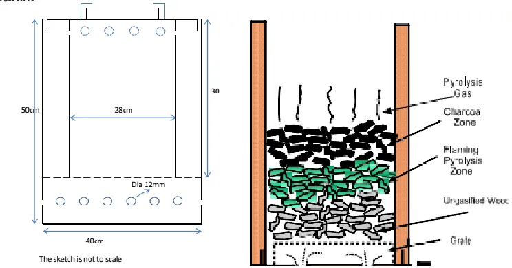
The inverted down draft (double) type of Wood gas stove was fabricated by Asella AERC workshop (figure 1). The outer cylinder
both end opened and a ring of ventilation holes drilled around the whole of the bottom edge of the cylinder and support rods are run
through the drum. These rods supports perforated sheet which forms grate. The inner cylinder both ends opened forms combustion
chamber. This cylinder fits inside the outer cylinder. It rests on the perforated sheet or grate which is supported by rods. This cylinder
has a ring of ventilation holes drilled around the upper end of the cylinder. The third cylinder which is only slightly smaller than the
outer cylinder is cut down to make a cap for the inner cylinder. The cap is not tight-fitting (1cm less than outer cylinder diameter); it
effectively closes off the top of the gap between the sides of inner cylinder and the sides of the outer cylinder. The cap has riser (to
increase combustion efficiency of producer gas) and circular hole cut in it, and this hole is only slightly smaller than the diameter of
the inner cylinder. It is supported by the upper lip of the combustion chamber but the hole is large enough so that it does not obstruct
the flow of heat up through the top of the combustion chamber. The pot seat is supported by the cap.
Fuel wood charge is lit on the top, forming a layer of charcoal, the flaming pyrolysis is below charcoal layer and the unburned fuel is
at the bottom on the grate. The primary air for the pyrolysis process is entered at bottom through holes drilled at the bottom of outer
cylinder and move up forming gases in the flaming pyrolysis zone as shown in the figure 2. The pyrolysis gas is combusted by
secondary air entered from the top through clearance of top cover and holes drilled on the top of combustion chamber above the
[image:3.612.54.508.426.646.2]charcoal zone and part of primary air which flow through whole between inner and outer cylinders.
Figure 1: Photo of the fabricated stove showing different parts
Pot seat
Riser
Top cover/cap
Outer cylinder
Primary inlet
holes
Combustion chamber
Grate
ISSN 2250-3153
Figure 2: shows 2D schematic drawing (left) and Wood gas stove showing combustion process (right)
2.4 Fuel Characteristics
The wood used for the experiments was Eucalyptus (local names bargamo) obtained from the center as leftover of different activities,
split and air-dried. Semi-cylindrical pieces of wood (2-4 cm in diameter and 25-30 cm in length) were used during each experiment.
The moisture content (11.67%) and the calorific value of fuel wood (4090cal/gram) were determined at the end of the entire series of
experiments by using oven drying method and bomb calorimeter respectively.
2.5 Performance evaluation
The Water Boiling Test (WBT) is a simplified simulation of the cooking process. It is intended to measure how efficiently a stove
uses fuel to heat water in a cooking pot and the quantity of emissions produced while cooking4. It measures the quantity of fuel
consumed and time required for the simulated cooking and usually employed in investigating the performance of cook stoves under
different operating conditions.
The standard WBT consists of three phases that immediately follow each other. The cold-start high-power phase, we begun the test
with the stove at room temperature and uses fuel from a pre-weighed bundle of fuel (5kg) to boil a measured quantity of water (5
Kg)in 7cm diameter stainless steel vessel. Then we replaced the boiled water with a fresh water of ambient-temperature to perform the
second phase. The hot-start high-power phase was conducted after the first phase while stove and cooking vessel were still hot.
Again, we used fuel from a pre-weighed bundle of fuel to boil measured quantity of water (5 Kg) in the vessel. Repeating the test with
a hot stove helps to identify differences in performance between a stove when it is cold and when it is hot. The simmer phase
provides the amount of fuel required to simmer a measured amount of water at just below boiling point for 45 minutes. This step
simulates the long cooking of legumes or pulses common throughout much of the world. During this phase, pre-weighed amount of
fuel was used to simmer the boiled water for 45 minutes.
As it is quick method of comparing the performance of cook stoves4, we employed in evaluating the performance of the improved
biomass cook stove and compared with the performance of the 3-stone traditional cook stove, which it intends to replace. For each
ISSN 2250-3153
2.5.1 Determination of stove performance parameters
a. Moisture content of fuel (M): The moisture content of fuel wood used was determined by the weight loss of sample that was oven-dried at 100°C until the weight of the sample stabilized. The Sample of moist fuel was taken from the fuel wood prepared
for the tests and oven dried as stated above. And moisture content was calculated by equation 1 and found 11.67%.
(1)
Where: Ww-is weight of wet fuel sample, Wd-weight of dry fuel (after oven dried)
b. Fuel consumed (dry base): The amount of fuel wood used to bring water temperature from room temperature to boil 8. And it
account for two factors: (1) the energy that was needed to remove the moisture in the fuel and (2) the amount of char remaining unburned. And given by:
Mass of dry fuel = Fuel mass (wet)*(1-M) (2)
c. Burning rate: A measure of the average unit of wood burned per unit of time during the test. Between tests, compares how consistently the user was operating the stove. Between stoves, indicates how rapidly the stove consumes fuel. And it is given by:
(3)
d. Firepower (Fp): This is a ratio of the wood energy consumed by the stove per unit time. It is a useful measure of the stove’s heat output, and an indicator of how consistently the operator ran the stove over multiple tests. And the firepower (Fp) is given by:
(4)
Where LHV- is lower heating value of the fuel
e. Turn-Down Ratio (TDR): Turn-Down ratio indicates how much the user adjusted the heat between high power and low power phases. A higher value indicates a higher ratio of high power to low power, and could signal a greater range of power control in
the stove.
(5)
f. Thermal efficiency (ηth ): Thermal efficiency is a measure of the fraction of heat produced by the fuel that made it directly to the water in the pot. The remaining energy is lost to the environment. So a higher thermal efficiency indicates a greater ability to
transfer the heat produced into the pot. While thermal efficiency is a well-known measure of stove performance, a better indicator
may be specific consumption, especially during the low power phase of the WBT. This is because a stove that is very slow to boil
may have a very good looking TE because a great deal of water was evaporated. However the fuel used per water remaining may
be too high since so much water was evaporated and so much time was taken while bringing the pot to boil4. And determined
using equation (6).
(6)
Where LHV-lower heating value of the fuel wood and LHW-is latent heat of vaporization of water.
g. Specific fuel consumption (SFC): This is a measure of the amount of fuel required to boil (or simmer) 1 liter of water. It is
ISSN 2250-3153
the end of the test. In this way, the fuel used to produce a useful liter of “food” and essentially the time taken to do so is
accounted for and given by equation (7).
(7)
h. Specific Energy Consumption (SEC)- It is a measure of the amount of energy required to boil (or simmer) 1 liter of water and given by:
(8)
i. Temp-Corrected Specific Fuel Consumption (SCTc )– This corrects specific consumption to account for differences in initial water temperatures. This facilitates comparison of stoves tested on different days or in different environmental conditions. The correction is a simple factor that “normalizes” the temperature change observed in test conditions to a “standard” temperature
change of 75 ºC (from 25 to 100)4. It is calculated in the following way:
(9)
j. Temp-Corrected Specific Energy Consumption (SET
c)– Similar to the temperature corrected specific fuel consumption, this metric is a measure of the amount of fuel energy required to produce one liter (or kilo) of boiling water starting with cold stove. It
is the temperature corrected specific fuel consumption multiplied by the energy content of the fuel4:
(10)
k. The local boiling point (Tb) of water is the point at which the temperature no longer rises, no matter how much heat is applied. The local boiling temperature is influenced by several factors including altitude, minor inaccuracies in the thermometer, and
weather conditions. For these reasons, the local boiling temperature cannot be assumed to be 1000 C. For a given altitude h (in
meters), the boiling point of water may be estimated by the following formula 2:
(11)
l. Temperature Corrected Time to Boil ( )– The time it took for the vessel to reach boiling temperature, corrected to reflect a temperature rise of 75 deg C from start to boil. This measure can be compared across tests and stoves to determine the “speed” of
the stove at high power, often an important factor to cooks4.
(12)
ISSN 2250-3153
3. RESULT AND DISCUSSION
3.1 Visual observations
Initially, the flames come out of the top of the stove, but after a few minutes, the combustion changes. The wood is slowly converted
to charcoal and the gas released by this process burns with higher flame height than the wood would give as well as burning for a
much greater length of time. After a while, flames no longer come out of the top of the stove, they come out of the ring of holes
around the base of the outer cylinder. The heat flowing out of the bottom gets diverted around the outside of the combustion chamber,
flows upwards, is caught by the cap and fed back into the combustion chamber through the ring of holes at the top of the combustion
chamber. The result attained was similar with 9.
3.2 Performance indicator parameters determined by the above equations
Both thermal and stove characteristics indicators discussed above under determination of performance parameter part of this paper is
summarized and statically discussed below.
Table 1: Calculation result summary
Description Cold start Hot start Simmering WGS TSCS WGS TSCS WGS TSCS
Phase duration (min) 17 44 13.3 40 45 45
Burn rate (g/min) 35 45 23 32 41 49
Thermal efficiency (%) 23.5 11 28.7 14 21 13.4
Specific fuel consumption (g/lit) 117 212 107 203 815 533
Specific energy consumption (KJ/lit) 1998 3543 1827 3393 14171 9261
Fire power (kw) 10.2 7.4 11.7 7.4 11.8 11.3
Turn down ratio 0.9 0.66
ISSN 2250-3153
Table 2: Mean comparison of cold start phase for WGS and TSCS
Parameters units
WGS TSCS Significance test
Mean STD COV Mean STD COV %mdf t-critical
Significance at
p<0.05
time to boil min 17 1 0.059 44 1 0.023 61.36 27.79 **
Tcore- time to boil min 16.79 1.29 0.077 42.31 0.96 0.023 60.31 19.52 **
fuel consumed (dry) g 596 40.63 0.068 1119 21 0.019 46.74 9.99 **
Burning rate g/min 35.19 4.09 0.116 25.44 0.81 0.032 27.7 2.15 ns
Ƞ (%) 23.5 0.01 0.038 10.8 0.005 0.045 54.25 11.13 **
SFC g/liter 116.59 8.42 0.072 212 3.05 0.014 45.01 7.28 **
Temp corrected SFC g/liter 114.97 5.54 0.048 203.9 2.93 0.014 43.61 12.056 **
Temp-corrected SEC kJ/liter 1998.15 96.31 0.048 3543 50.94 0.014 43.6 12.06 **
Firepower watts 10193.6 1183.8 0.116 7369 235.0 0.032 27.8 2.15 ns
From the mean comparison of cold start high power phase (table 2), the Wood Gas Stove performed significantly better than Three
stone Cooking stove for most of performance indicators of stoves except for stove characteristic indicators (Burn rate and fire power)
where the stoves performance was not significantly different at P<0.05.
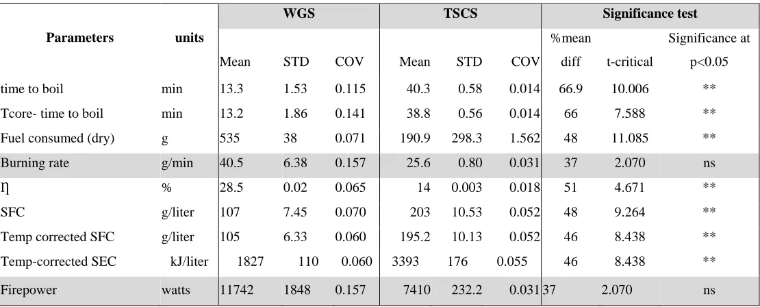
Table 3: Mean comparison of hot start phase for WGS and TSCS
Parameters units
WGS TSCS Significance test
Mean STD COV Mean STD COV
%mean
diff t-critical
Significance at
p<0.05
time to boil min 13.3 1.53 0.115 40.3 0.58 0.014 66.9 10.006 **
Tcore- time to boil min 13.2 1.86 0.141 38.8 0.56 0.014 66 7.588 **
Fuel consumed (dry) g 535 38 0.071 190.9 298.3 1.562 48 11.085 **
Burning rate g/min 40.5 6.38 0.157 25.6 0.80 0.031 37 2.070 ns
Ƞ % 28.5 0.02 0.065 14 0.003 0.018 51 4.671 **
SFC g/liter 107 7.45 0.070 203 10.53 0.052 48 9.264 **
Temp corrected SFC g/liter 105 6.33 0.060 195.2 10.13 0.052 46 8.438 **
Temp-corrected SEC kJ/liter 1827 110 0.060 3393 176 0.055 46 8.438 **
Firepower watts 11742 1848 0.157 7410 232.2 0.031 37 2.070 ns
From Table 3, during hot start high power test Wood Gas Stove (WGS) performs significantly better than Three stone Cooking stove
(TSCS) for most of the performance indicators except for stove characteristic (Burn rate and fire power) where stoves performances
[image:8.612.29.584.381.605.2]ISSN 2250-3153
Table 4: Mean comparisons during simmering test of the stoves
Parameters units
WGS TSCS Significance Test
Mean STD COV Mean STD COV
%Mean
diff t-critical
Sign. at
p<0.05
Fuel consumed (dry) g 1769.8 189.17 0.107 1749 179.9 0.103 1.15 1.527 ns
Burning rate g/min 39.33 4.21 0.107 38.9 4 0.103 1.15 1.529 ns
Ƞ % 20.4 0.01 0.049 13.4 0.02 0.147 34.10 3.47 **
SFC g/liter 814.8 202.27 0.248 532.9 59.5 0.112 34.60 1.326 ns
Temp-corrected SEC kJ/liter 14161.3 3515.4 0.248 9261 1034.6 0.112 34.60 1.326 ns
Firepower watts 11392 1218.3 0.107 11261 1157.8 0.103 1.15 1.529 ns
Turn down ratio -- 0.895 0.042 0.047 0.659 0.068 0.104 26.36 3.598 **
From Table 4, Most of the performance indicators of the stoves were not significantly different except for thermal efficiency and Turn
Down Ratio where WGS performed significantly better than TSCS at p<0.05.
3.3 Comparisons of performance parameters
Both thermal performance and stove characteristic indicators were elaborated.
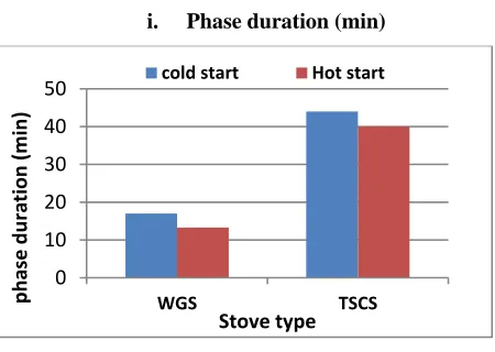
i. Phase duration (min)
Figure 3: Phase duration comparison of WGS and TSCS
Least boiling time was recorded during high power hot start phase (13.3min and 40min) by WGS and TSCS respectively. The result
obtained by the experiment was similar with 6, 7. The boiling time reduction during high power hot start by the stoves were due to heat
absorbed by stove body in this phase. Taking the mean of high power tests, the technology improved cooking time by 67.4%.
ii. Burning rate comparison
0 10 20 30 40 50
WGS TSCS
ph
ase
du
ra
tion
(min)
[image:9.612.194.419.332.492.2]ISSN 2250-3153
Figure 4: Burning rate comparison
Least burn rate was recorded during hot start by WGS (23g/min) and simmering test by TSCS (32g/min). Highest burn rate was
recorded during simmering test by WGS (41g/min) and TSCS (49g/min). Comparing burn rate the WGS performs better than TSCS,
but it was not significant at tested significance level as indicated in Table 4.
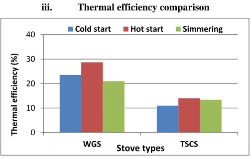
iii. Thermal efficiency comparison
Figure 5: Shows how thermal efficiencies of the stoves compared
The highest thermal efficiency was recorded during hot start and simmering test by WGS and TSCS respectively. Least efficiency
was recorded during simmering test and cold start test by WGS and TSCS respectively. The high power thermal efficiency were 26%
and 12% for WGS and TSCS respectively and low power efficiency were 21% and 13.5% for WGS and TSCS respectively. 0
10 20 30 40 50 60
WGS TSCS
b
u
rn
rate (
g/
min
)
Stove types
Cold start Hot start Simmering
0 10 20 30 40
WGS TSCS
The
rmal
e
ff
ici
e
n
cy
(%)
Stove types
[image:10.612.180.433.315.475.2]ISSN 2250-3153
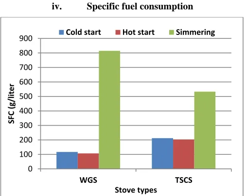
[image:11.612.180.433.54.256.2]iv. Specific fuel consumption
Figure 6: Shows the comparison of specific fuel consumptions
Specific fuel consumption is the measure of stove fuel consumption to boil a unit of water. Least sp. fuel consumption was recorded
during hot start and cold start by WGS and TSCS respectively. As indicated, for high power test WGS recorded least SFC and low
power test was recorded least SFC by TSCS. Comparing the two stoves during high power test WGS improved SFC by 46.5 while
during lower power TSCS performs better than WGS.
v. Turn Down Ratio comparison
Figure 7: Compares the turn down ratio of the stoves
Comparing the mean Turn down ratio (TDR) of the stove Wood Gas Stove performed better than three stone cooking stove by 26%. 0
100 200 300 400 500 600 700 800 900
WGS TSCS
SFC (g/
lite
r
Stove types
Cold start Hot start Simmering
0 0.2 0.4 0.6 0.8 1
[image:11.612.203.411.384.524.2]ISSN 2250-3153
4. CONCLUSION AND RECOMMENDATION
4.1 Conclusion
The Wood Gas Stove improved the thermal efficiency by 54% during high power tests and 36% in low power test when compared
with Traditional cooking stove (TSCS). It can contribute to indoor air pollution reduction and afforestation in developing countries.
Comparing the mean the power controllability of the tested stove WGS performs better than TSCS by 26%. The stove performed
better than TSCS for all performance indicators of thermal parameters. The technology performed better than traditional stove by
most of thermal performance indicators except specific fuel consumption during low power test, it is important to promote to end
users.
4.2 Recommendation
Since the technology was performed better than traditional cooking by most of thermal indicators, it was recommended to be
promoted and collect end users comment for further dissemination.
Modifying the technology to decrease thermal mass so that it could be easily used in house hold cooking condition and applying
insulation on the outer cylinder.
The evaluation was under taken on hard wood, so it was recommended to further evaluate on different feedstock available in
local area
REFERENCE
1. https://en.wikipedia.org/wiki/Wood_gas (accessed on oct 29, 2019),
2. Christa Roth, 2013. Micro-gasification:cooking with gas from dry biomass. giz, 2nd reviced edition.
3. T.B.Reed and Ronal Larson, 1996. A Wood gas stove for developing countries. The biomass foundation, Golden, CO., USA. Presented at the “developments in thermochemical Biomass Conversion” conference, Banff, Canada.
4. Rob Bailis, Damon Ogle, Nordica MacCarty. The Water Boiling Test (WBT) version 4.2.3. For the Household Energy and
Health Programme, Shell Foundation (unpublished manual).
5. Parashuram Nandi, Amol Nayakappa Patil, Nagaraj Raikar, Sidharth Kasturi, Mahalingesh B (2016). Performance
Evaluation of Improved Biomass Cook Stove. International Journal of Scientific Engineering and Research, Volume 4 Issue
11, November 2016.
6. M.S Islam, M.Khanam, M.A. Rouf and M.Rahaman, 2014. Performance evaluation of ICS disseminating in Bangladesh.
Bangladish Journal of scientific and industrial research.
7. Sabrina Khan, Tania Hossain, Md.Mominur Rahman, 2016. Development of portable Rocket stove and performance
evaluation. International journal of Enginering and technology, volume: 03 issue 12, Dec 2016.
8. Teka Tesfaye Mangesha and Ancha Venkata Ramayya, 2017. Performance Evaluation of Pyrolysis Cook stove Using
Water Boiling Test. American Journal of Modern Physics.
9. http://www.free-energy-info.tuks.nl. A Practical Guide to Free-Energy Devices. Chapter 14: Renewable Energy Devices. By