© 2017, IRJET | Impact Factor value: 5.181 | ISO 9001:2008 Certified Journal
| Page 1577
ADVANCED INTEGRATED MODELING AND ANALYSIS FOR ADJUSTABLE
SPEED DRIVE OF INDUCTION MOTORS OPERATING WITH MINIMUM
LOSSES
AMEER BHASHA
1, M.SIVAKUMAR
2, M. SHOBBHA
31
PG Scholor, MTECH (PE), CVRT, Andhrapradesh, India
2
Assistant Professor, Dept of EEE,Andhrapradesh, India
3
Associate Professor & HOD, Dept of EEE, CVRT, Andhrapradesh, India
---***---
Abstract:- The nonlinear induction motor model issuitably coordinated by joining the flow of the power electronic converter in a way that allows the plan of stable field-oriented control (FOC) working with least misfortunes. As officially demonstrated, the testing issue of working the induction machine with least copper misfortunes requires a changing rotor flux contradicted to the standard FOC method, which keeps the rotor field size steady and tracks the electric torque to the coveted level. To this end, misusing the Hamiltonian structure of the created motor/converter demonstrate, an enhanced nonlinear controller is suggested that ensures the specialized furthest reaches of the converter (direct balance) and at the same time works under FOC at relentless state to accomplish precise speed control with fluctuating rotor flux as indicated by the insignificant misfortunes prerequisites. Under these conditions, the traditional FOC stability investigation does not hold any longer, and in this manner interestingly, another thorough examination is given that demonstrates stability and meeting to the coveted harmony for the total shut circle motor converter system. At long last, the hypothetical commitment is analyzed in contrast with the customary FOC operation by recreations got for a mechanical size induction motor, while it is additionally assessed by continuous consequences of a motor with comparable parameters.
INTRODUCTION
The three stage induction motor addresses a champion among the most typically utilized electric machines in mechanical applications. The coordination of sensible power electronic gadgets, particularly cooling/dc voltage source converters (VSC), have conclusively expanded the zone of usages for the induction machine and has opened another field in outline and examination. Vector or field-oriented control (FOC), however astounding and requesting strategy, remains a successful mechanical assembly for flexible induction motor speed drives , since it achieves consistent rotor flux greatness that revamps the electromagnetic torque explanation as in an autonomously energized dc motor. On the other hand, the motor profitability change, happening in light of the
decrease of copper misfortunes, has transformed into a huge working endeavor caused by environmental or extraordinary application reasons, for instance, wind turbine or electric vehicle capable operation . As it has been showed up, control misfortunes minimization without a doubt requires a fluctuating rotor flux size in agreement to the particular working point.
Moreover, in all induction motor applications, security expect a fundamental part in system operation and ought to be continually ensured. A couple of researchers have proposed FOC techniques to guarantee soundness of the induction motor using the decreased request ebb and flow sustained model of the motor, i.e., by considering a third-arrange system with states the rotor fluxes and the motor speed, while the stator currents are the control inputs. Adding to the model examination the stator current flow, asymptotic steadfastness has been shown recently under the usage of parameter or load torque estimators or adjustment instruments. This suggests extra unique outlines are required, while w when the induction motor should work with minimum misfortunes, it transforms into an ungainly errand to lead a similar quality examination, since the controller operation is far from the standard FOC plan. In addition, in all the present written work, the converter elements, however vital for the system unfaltering quality, are totally excluded, routinely in perspective of their nonlinear structure which assembles the trouble. It is in this way obvious that a whole system displaying is required that considers the nonlinear structure of both the VSC and the induction motor. Also, on this aggregate model, essential control plans without extra unique parts that can't be easily actualized must be created, while their dynamic execution ought to irrefutably ensure system quality under operation with reliable or fluctuating flux greatness. In this edge, some early results have been proposed by the makers in for a standard FOC approach.
© 2017, IRJET | Impact Factor value: 5.181 | ISO 9001:2008 Certified Journal
| Page 1578
system is acquired in a seventh-arrange state-spacenonlinear shape that incorporates both the aeration and cooling system motor and the VSC elements in the synchronously turning d-q reference plot .The controlled wellsprings of data are specifically the VSC obligation extent d-q segments while the provided voltage and the heap torque are considered as outside commitments with the second one thought to be absolutely dark with step-contrasting size. Receiving the examination displayed, it is first reasoned that keeping in mind the end goal to finish slightest copper misfortunes, the square of the rotor flux greatness ought to be straightly needy from the electric torque. Expanding the technique under FOC relentless state operation, it is exhibited that the d-q obligation extent input parts can be utilized for the speed course through the q current after, while the motor adequacy takes its most prominent motivating force by dealing with the d current section in a predictable extent concerning the q current portion. Regardless, since for this circumstance, the conventional
vector control examination can't guarantee
dauntlessness with the usage of clear Proportional-Integral (PI) controllers the basic responsibility of the present work is that the proposed system demonstrating awards the outline of new essential nonlinear dynamic controllers, prepared for vanquishing these disadvantages. As exhibited in the present paper, the shut circle system is consistent and converges to the coveted balance with the rotor flux size after the heap assortments in a way that ensures slightest misfortunes and field presentation at enduring state. It is striking that a middle of the road result from the embraced minimum misfortunes examination is that of reliable slip recurrence prerequisite under various load conditions. It is moreover colossal to observe that for this circumstance, as it is showed up in the venture, soundness is accomplished without requiring any flux greatness and edge estimation while the controller parameters are totally free from the system parameters and the different state factors beside than the controlled ones; this significantly prompts clear control outlines, adequately and straightforwardly executed on the d-q obligation extent segments in spite of the way that their progression are nonlinear. The general plan can similarly guarantee that the control signals, particularly the obligation extent signals, are normally limited in the predefined run where the converter works with straight adjustment. A modern size 22.4-kW induction motor encouraged by a VSC is utilized to speak to the proposed approach while connections with the customary FOC strategy check the proposed minimum misfortunes operation. Reenactment comes to fruition acquired with MATLAB/Simulink or a lab progressing OPAL RT system improvement are given to check the proposed approach. The venture is sorted out as takes after. the whole system display including the nonlinear converter
elements and the d-q elements of the induction motor is gotten, while the current FOC is immediately introduced.
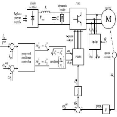
VSC CONVERTER AND INDUCTION MOTOR ANALYSIS
The system under thought comprises of a diode rectifier, a dc-interface, and a three-stage VSC encouraging a three-stage induction Fig. 1. Schematic graph of the system under thought. motor, as appeared in Fig. 1.Adc-connect capacitorC and a smoothing inductor L are utilized as a part of the dc-interface alongside their parasitic resistances RC and RL , separately.
Utilizing the synchronously turning d-q reference outline [1] and expecting as state factors of the induction motor the stator currents ids, iqs, the rotor fluxes λdr , λqr , and the motor speed ωr , the generally utilized dynamic model of the induction motor can be acquired
Subsequently, customary FOC strategies give a steady reference an incentive to the flux which can be changed into a consistent reference for the current¯ids = iref ds . Conventional PI and fell
© 2017, IRJET | Impact Factor value: 5.181 | ISO 9001:2008 Certified Journal
| Page 1579
NONLINEAR CONTROLLER FOR ACHIEVING MINIMUM LOSSES
Thus, if the stator currents are controlled in agreement, at that point operation with universally least misfortunes is accomplished as long as the subsequent flux size is underneath its upper passable bound. In handy applications, in any case, the figured lopt esteem is too little, bringing about inadmissible high flux sizes; at that point, the significance of is to choose the littlest conceivable incentive for the lopt (greater than the one computed which can guarantee operation with locally least misfortunes and flux size reinforced near its upper bound. Under these conditions, stability examination ought to be constantly ensured at enduring state as well as amid the transient execution too. Such an examination in light of a controller that accomplishes all the past undertakings and which gives exact speed direction
[image:3.595.320.553.95.278.2]SIMULATION RESULTS
Fig 4.Advanced integrated modeling and analysis for adjustable speed drives.
[image:3.595.61.250.325.514.2]Fig.5.advanced integrated modeling and analysis
Fig.6.outpu waveforms
[image:3.595.330.536.335.424.2]© 2017, IRJET | Impact Factor value: 5.181 | ISO 9001:2008 Certified Journal
| Page 1580
Fig8 .stator current waveformsFig.9.Rotor flux waveforms
Fig.10.output waveforms with minimum losses
Fig.11.voltage and current output waveforms
Fig.12 d-axis stator current.
Fig.13 q-axis stator current.
© 2017, IRJET | Impact Factor value: 5.181 | ISO 9001:2008 Certified Journal
| Page 1581
Fig.15.q-axis stator currentCONCLUSION
In this venture report, a whole nonlinear system displaying of a VSC-sustained enlistment engine was exhibited, and a nonlinear dynamic controller was proposed to achieve exact engine speed course with minimum misfortunes. Considering the changing rotor flux hypothesis, the connection between the stator streams is gotten to restrict the power misfortunes and fulfill field introduction at consistent state.
Both the current and speed course is executed by a nonlinear controller that is totally autonomous from the system parameters and produces limited obligation extent flags dependably inside as far as possible as they are set by the straight regulation district of the converter.
In light of the whole system flow and the controller structure, nonlinear shut circle system strength is shown where the system states are ensured to remain limited and meet to the coveted balance. Adding to the thorough steadiness examination the way that the controller can be effectively executed with no flux measurements or estimation required, this control conspire sets up a clearly advanced stride in aerating and cooling engine drives that conclusively upgrades the current
REFERENCES
[1] B. K. Bose, Modern Power Electronics and AC Drives. Upper Saddle River, NJ, USA: Prentice-Hall, 2002
.[2] N. P. Quang and J.-A. Dittrich, Vector Control of Three-Phase AC Machines: System Development in the Practice. New York, NY, USA: Springer, 2008.
[3] G. D. Marques and D. M. Sousa, “Stator flux active damping methods for field-oriented doubly fed induction generator,” IEEE Trans. Energy Convers., vol. 27, no. 3, pp. 799–806, Sep. 2012.
[4] Y. Zhou, P. Bauer, J. A. Ferreira, and J. Pierik, “Operation of grid connected DFIG under unbalanced grid voltage condition,” IEEE Trans.
Energy Convers., vol. 24, no. 1, pp. 240–246, Mar. 2009. [5] G.Kenne, T.Ahmed-Ali, F. Lamnabhi- Lagarrigue, and A. Arzande, “Realtime speed and flux adaptive control of
induction motors using unknown time-varying rotor resistance and load torque,” IEEE Trans. Energy Convers.,vol. 24, no. 2, pp. 375–387, Jun. 2009.
[6] A. Makouf, M. E. H. Benbouzid, D. Diallo, and N.-E. Bouguechal, “Apractical scheme for induction motor speed sensor less field-oriented control,”IEEE Trans. Energy Convers., vol. 19, no. 1, pp. 230–231, Mar.2004. [7] M. K. Bourdoulis and A. T. Alexandridis, “Direct power flow modeling and simple controller design for ac/dc voltage-source converters,” in Proc.39th Annu. Conf. IEEE .
[8] M. K. Bourdoulis and A. T. Alexandridis, “Nonlinear stability analysis of DFIG wind generators in voltage oriented control operation,” inProc. Eur. Control Conf., 2013, pp. 484–489.
[9] M. K. Bourdoulis and A. T. Alexandridis, “Rotor-side cascaded PI controller design and gain tuning for DFIG wind turbines,” in Proc. 4th Int.
Conf. Power Eng. Energy Elect. Drives, 2013, pp. 733– 738.
[10] R. P. d. M. Martins, D. M. Sousa, V. F. Pires, and R. A.,, “Reducing the power losses of a commercial electric vehicle: Analysis based on an
asynchronous motor control,” in Proc. 4th Int. Conf. Power Eng. Energy Elect. Drives, 2013, pp. 1247–1252. [11] Z. Qu, M. Ranta, M. Hinkkanen, and J. Luomi, “Loss-minimizing flux level control of induction motor drives,” IEEE Trans. Ind. Appl., vol. 48,no. 3, pp. 952–961, May/Jun. 2012.
[12] C. Canudas de Wit, and J. Ramirez, “Optimal torque control for current fed in,” IEEE Trans. Autom.
[13] W.-J. Wang and J.-Y. Chen, “Compositive adaptive position control of induction motors based on passivity theory ,”IEEETrans. Energy Convers., vol. 16, no. 2, pp. 180–185, Jul. 2001