© 2017, IRJET | Impact Factor value: 5.181 | ISO 9001:2008 Certified Journal | Page 2997
Door Sag Evaluation of Clothes Dryer by using FEA and Influence of it
on Effectiveness of Door
Rakeshkumar Krishnat Patil
1, M.R.Khodke
2, Anish Sasidharan
31
P.G Student, Vishwakarma Institute of Technology, Mechanical Department, Maharashtra, Pune
2Professor, Vishwakarma Institute of Technology, Mechanical Department, Maharashtra, Pune
3
Fabric Care Department, GTEC-Whirlpool of India Ltd., Pune
---***---Abstract -
Hinge provide the door to swing, attaches the
doors to cabinets door panel, bear the entire load and allows limited angular movement. Generally it is subjected to Door Load due to its self-weight and torsion load towards the Cabinet. As per as customer point of view concern door is only part which is handled frequently in case of most of the consumer appliances so that it is very important to design Door hinges with updated handling considerations of present and futures like unusual handling by child, serviceman etc. In such cases some amount of extra load may get applied which can be resulted into failure of hinges. The aim of this research paper is to check performance of optimized Dryer door hinge in such a way that it should pass all design requirements like it should take the door load and transfer the torsion load to the cabinet without door sagging, it should provide smooth door opening and closure without exceeding the ergonomic limits etc. Modeling of hinges has been carried out by using modeling software CREO 3.0 and its deflection Analysis is planned to be carried out by using FEA software ANSYS. Prototype model is developed and tested on Door sagging test rig for its performance. The results obtained from FEA are compared with experimental results. Propose generalized correlation to avoid experimentation.
Key Words: Ergonomic limits, deflection Analysis, FEA,
ANSYS workbench.
1.INTRODUCTION
Using a force and moment balance analysis, the simple mechanical loads from the closing of the door were calculated. The failure modes and mechanisms found experimentally were similar to those of the failed sample in the field. Failure analysis, accelerated life tests and corrective action plans were used to identify the key control parameters and level for the mechanical hinge kit system [1]. To avoid the failure of fastener joints, standard topology optimization is extended not only to minimize the structural compliance but also to control shear loads intensities over fasteners. [2]. Using nonlinear finite element analysis, a seal cross section can be analyzed for compression load deflection (CLD) performance, contact pressure distribution and aspiration due to a pressure differential across the seal. The seal CLD reply, the deformed shape during compression,
the contact pressure distribution and the aspiration pressure difference are all important seal performance factors that are reflected in door weather ship seal design [3].Identifying potential design considerations for manufacturers, and the importance of testing a diversity of different materials and components to meet the requirements for compliance [4]. Engineering Optimization Theory and Practice [5].
Comparatively less work is done in the area of Door sag evaluation of consumer appliances. Hence in the present study we focused on door sag evaluation and effectiveness of door at various hinge positions.
2.
CAD MODELLING OF HINGE
Modelling of hinges is carried out in design tool CREO 3.0 considering design, geometric and manufacturing aspects. The best design as shown in fig.1 is selected among the all optimized hinges by using concept selection criteria.
[image:1.595.347.528.477.611.2]a. Upper Hinge b. Lower Hinge
Figure 1: Dryer Door Hinges
3. UNDERSTANDING DOOR OPENING AND CLOSING
FORCES:
© 2017, IRJET | Impact Factor value: 5.181 | ISO 9001:2008 Certified Journal | Page 2998 understand the behavior of hinges before and after applying
of safety load.
The door is held in the closed position with the help of catch and strike. When strike is pushed against catch it engages to hold the door closed and when the handle of the door is pulled to open the door, the catch expands to allow the strike to move out. The positions of the catch and strike are shown of the door and front panel respectively. Bumpers are small rubber component which prevent the direct impact of the door on the front panel and is compressed to some extent when the door is in closed condition. Door seal prevent the leakage of air into the dryer drum as the pressure in the dryer drum is less than the atmosphere and leakage of air leads to the reduced drying efficiency. The main reason of this failure is door sag due to failure of hinges.
The Fig 2 shows the components of Door assembly and front panel and their location with respect to the hinge position. The Fig 3 showing the geometric configurations of the catch and strike.
[image:2.595.363.505.134.254.2]
Figure 2: Dryer door components
(a) (b)
Figure 3: Catch and Strike geometric configurations
It is very important to know the parameters of catch and strike in order to check the performance of the hinges .The Figure 4 showing the force layout of strike.
F = K*(W-x)*Sin (A) / [ cos (A-B) - µ* Sin(A-B)]
F = vertical force need to be exerted to engage the strike K= Stiffness of spring
W=maximum width of strike
x= Initial gap between bushings
µ= Coefficient of friction between strike and bushing
Figure 4: Force Layout of strike
3.1 Door Closing Force:
If F is the force that user need to apply for closing the door neglecting all forces, other than catch forces on the door. Then,
F= (L2/L1)*C
But since there are other forces contributing to door forces, the actual door Closing force which user need to apply is :
[image:2.595.64.263.359.523.2]F’ = F + (Seal Back Force) + (Door Switch Back Force + (Bumper Back Force) + (Force due to Hinge Friction)
Figure 4: Closing Force Layout
3.2
Door Opening Force:
If F is the force that user need to apply for opening the door, neglecting all forces other than catch forces on the door. Then,
F= (L2/L1) * C
[image:2.595.365.504.466.553.2]© 2017, IRJET | Impact Factor value: 5.181 | ISO 9001:2008 Certified Journal | Page 2999 Figure 5: Opening Force Layout
Before taking the other parameters in to consideration we have to calculate the reaction forces at the hinge positions. The reactions at both hinges are same in magnitude due to symmetrical as per our assumptions. Hence no need to calculate reaction at both hinges.
As per design specifications the opening force is always greater than closing force hence we are considering just opening force with and without safety force
Taking moment at the upper hinge without safety load R1*H=W/2*Door weight
R1*0.570=0.3*68.67 R1=36.14 N
Taking moment at the upper hinge with safety load R1*H=W/2*Door weight + W*safety load
R1*0.570=0.3*68.67+0.6*222.6 R1=270.46 N
Where W is width and H is the height of the door in meter .Although load of door is acted on hinge but its partial effect is on hinge plate and bolt also hence we have to check mechanical properties of all contact bodies.
4. FEA ANALYSIS:
4.1 Door Specifications and boundary conditions:
1. Door dimensions: 600mm*35mm*570mm
2 . Hinge located at 40 mm from upper and lower side 3. Remote Forces acting on hinges: Weight of door located at C.G (68.67N) and Safety load located at upper left corner (222.5 N)
4. Loading conditions are applied on holes and located at respective positions.
4.2 Methodology:
1.Both hinges are kept in same plane and assigned different coordinate system for two different leaves of the hinges 2. Contacts given as per geometry (bonded , frictional..etc) 2.one leaf kept fix zero degree and other kept at 90 degree and remote load is applied.
3. Location of forces is given (x,y,z)
4. Get results (average equivalent von mises stress, strain, total deformation..etc) for different circumstances.
4.3 Meshing Detail:
Meshing of Clean Geometry After making sure that all geometry is ready initiate the meshing. Following are points need to consider in meshing.
A) We required to carry out the meshing on mid-surface that we have got from clean geometry B) Select element size according geometry C) Create the washer where ever required so have smooth flow of mesh D) The Mesh density necessary to check at critical areas.
4.4 Door Specifications and boundary conditions:
1. Door dimensions: 600mm*35mm*570mm
2. Hinge located at 40 mm from upper and lower side 3. Remote Forces acting on hinges: Weight of door located at C.G (68.67N) and Safety load located at upper left corner (222.5 N)
4. Loading conditions are applied on holes and located at respective positions.
4.5 Methodology:
1.Both hinges are kept in same plane and assigned different coordinate system for two different leaves of the hinges 2. Contacts given as per geometry (bonded , frictional..etc) 2.one leaf kept fix zero degree and other kept at 90 degree and remote load is applied.
3. Location of forces is given (x,y,z)
4. Get results (average equivalent von mises stress, strain, total deformation..etc) for different circumstances.
4.6 Solution Information:
The area where the screw is going to fit is made fixed and remote load is applied at remote location of the center of gravity and cantilever end as shown in fig 6 below. These two locations are connected by the mass elements as shown as below figure in red color .when load is applied these mass elements works as beam and indirectly applies the load over the screw location of hinges.
Fig 6. Solution information
© 2017, IRJET | Impact Factor value: 5.181 | ISO 9001:2008 Certified Journal | Page 3000 the average equivalent von mises stress, strain, total
[image:4.595.32.277.157.404.2]deformation is calculated as shown in figure 7 below using ANSYS workbench.
Fig 7: simulation results considering worst condition
[image:4.595.315.554.281.392.2]4.7 Simulation results:
Table 1: simulation results for hinges with considering the safety load
The table 1 showing the simulation results for hinges with considering the safety load. As per as simulation results concerns following points needs to be noted:
Von mises stress < ultimate tensile stress at 90 degree Hence design won’t fail at 90 degree angle.
The Average total deformation noted is negligible as compared to safety criteria
Yielding effect is locally distributed not throughout the cross section hence it passes in safety norms
5. EXPERIMENTAL ANALYSIS:
5.1 Testing and validation - 1:
There shall be no damage to the door, front panel or hinges that affect function or appearance when 50 lbs is placed on extreme outer edge of the door for one minute when it is open to the point of maximum leverage. The fig 8 showing the test rig for door sag test.
For initial testing, the data can be noted down during each 5,000-cycle inspection. After multiple assemblies have been tested, data can be noted down at the conclusion of the 15,000-cycle test.
Fig 8: Door sag test rig
5.2 Success criteria:
After application of the Door load, the Dryer must meet all of the following requirements:
A) There shall be no visible damage to the Front Panel, Door, or Door Hinges
B) The Door closing force must be smooth and the Door must still operate properly.
C) The Door to Front Panel fit must remain acceptable. D) The Dryer's Door opening force performance specified as per standard must still be in compliance.
E) The Dryer's Door leakage performance specified as per standard must still be in compliance. The following points are needs to be noted down for every 5000 cycles.
Every 5,000 cycles perform the following:
Measure door opening force
Measure door closing force
Visually inspect door strike – is strike loose in the front panel
Measure the Outer Diameter of the door strike – is material being worn away
© 2017, IRJET | Impact Factor value: 5.181 | ISO 9001:2008 Certified Journal | Page 3001
Visually inspect overall door structure – any rattles, noises, screws backing out (hinges, outer window, handle)
Visually inspect hinges – finish chipped, hinges bent
If finish chips/flakes are found, measure the size (mm) and then measure size at each 5,000 cycle increment
Visually inspect door seal – attachment to door, tearing, breaking down
5.3 As per UL standards machine need to pass
these criteria:
For Door Opening Force : Acceptable 8-14 lbs
For Door Closing Force : Acceptable 11lbs
For Inner Door Entrapment Load : Door opens with a Force ≤ 67N, applied from inside the clothes drum
For Door Air Leakage : Less than 2% air leakage
For Door Reversibility : Ability to reverse door opening direction
5.4 Results – I :
(a)
(b)
(c)
[image:5.595.298.555.55.379.2](d)
(d)
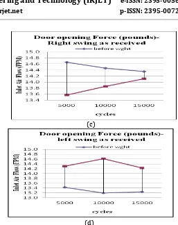
Fig 9: Testing results for door opening and closing forcesby using Power panel, Air flow meter, Pull force gauge. The fig 9 showing testing results for door opening and closing with and without safety weight by using Power panel, Air flow meter, Pull force gauge.
Measured door opening force (average) = 13.8
Visually inspect door strike (is strike loose in the front panel) – NO
Measured the Outer Diameter of the door strike (is material being worn away) - NO
Visually inspect door catch (attachment to door, finish degradation ) is OK
Visually inspect overall door structure - any rattles, noises, screws backing out (hinges, outer window, handle) – NO
Visually inspect hinges (finish chipped, hinges bent) – NO
If finish chips/flakes are found, measure the size (mm) and then measure size at each 5,000 cycle increment
© 2017, IRJET | Impact Factor value: 5.181 | ISO 9001:2008 Certified Journal | Page 3002
5.5 Testing and validation - 2:
Several fixturing combinations were attempted to support the stationary side of the hinge assembly, but in each case, fracture or movement of the base occurred before peak loading could be obtained on the hinge.
Perform 50lb door testing on Dryer Unit with new Hinges - Eliminated Spacer and modified the stationary leaf. Record amount of door defection with 50lb load. Door should be tested at 90 degree opening
After review of preliminary results, consensus was that the intended isolation of the load to the small hinge arm at the bottom of the assembly was not being obtained.
Test Duration: 15,000 cycles 1 cycles = door open/door close Door Opening angle to be 90o
[image:6.595.315.557.67.238.2]The test is completed at 15,000 cycles, or if a component failure prevents the door from opening and closing properly. The fig 10 showing test set up for door sag measurement by using fixture arrangements
Fig 10: fixture set up for door sag
5.6 Results and Discussion-2:
The fig 11 showing testing results for door sag in inches with safety load by using fixture set up .
(a)
(b)
Fig 11: fixture position and cumulative door sag readings
5.7 Door Deflection Height:
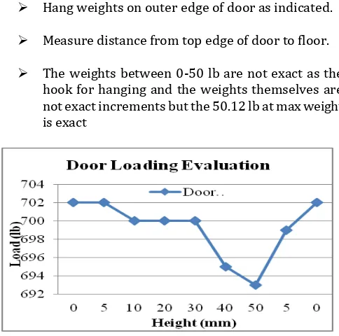
Hang weights on outer edge of door as indicated.
Measure distance from top edge of door to floor.
[image:6.595.314.556.299.539.2] The weights between 0-50 lb are not exact as the hook for hanging and the weights themselves are not exact increments but the 50.12 lb at max weight is exact
Fig 12: Door loading evaluation
6. CONCLUSIONS:
1) As from results of FEA and Testing of optimized hinge we can say that the stress and sag performance of optimized hinge satisfies the requirement of allowable displacement at latch point . The dryer door hinge change assessed under this report meets door loading success criteria and is accepted for production for this requirement.
[image:6.595.46.280.381.494.2]© 2017, IRJET | Impact Factor value: 5.181 | ISO 9001:2008 Certified Journal | Page 3003
7. FUTURE WORK:
1) There is no such standard for hinge selection including selection of hinge design , material to be used , placement location according to door geometry and mass properties so by analysing the results from no of outcomes and by checking out different concept selection matrix We can set the approximate standard for selection of hinge.
2) Accelerated life testing to predict service life and reliability for an appliance Door Hinge
ACKNOWLEDGMENT
I want to extend my sincere gratitude towards Mr. Anish Sasidharan and Sugadevan Devendiran from GTEC-Whirlpool of India Ltd., Pune for allowing the experimentation required for the test and helping in simulation work and optimization work of hinge.
REFERENCES
[1] Seong-woo Woo, Denns L. O’neal, Michael Pecht, Design of a hinge kit system in a Kimchi refrigerator receiving repetitive stresses, Engineering Failure Analysis 16 (2009) 1655–1665.
[2] A Oinonen, P. Tenskanen, T. Bjork, G. Marquis, Pattern optimization of eccentrically loaded multi-fastener joints Struct Multidisc Optim (2010) 40:597–609.