© 2016, IRJET | Impact Factor value: 4.45 | ISO 9001:2008 Certified Journal | Page 467
An Improved Design of Micro-Hydro Electric Power Plant
Dr.D.Vimalakeerthy
1, Humaid Abdullah Fadhil Al-Hinai
2, Hamood Salim Mohamed Al-Bimani
31
Lecturer,
Electrical Power Engineering Department, Nizwa College of Technology, Sultanate of Oman
2Instructor,
Electrical Power Engineering Department, Nizwa College of Technology, Sultanate of Oman
3
Student,
Electrical Power Engineering Department, Nizwa College of Technology, Sultanate of Oman
---***---Abstract -
In developing countries scarcity of electricalpower is the major problem and it needs to be taken care. Also it is not adequate to use fossil fuel as a conventional source for production of electrical power. Hydro power plant is considered to be an environment friendly solution in the countries where rivers are available, for serving rural electrification. Hydro power plants are attracting the power producing industries due to their low administrative and executive costs, possibility of using water for irrigation and drinking purposes, suitability for rural areas and low pollutions for the environment. In this paper an attempt has been made to develop a micro Hydro power plant model that can be used as a battery charger or temporary power supply in case of remote areas. With MATLAB/SIMULINK, the models of the proposed simulation system are all modularized and visualized, and can be reused easily. Solid works has been used to evaluate the mechanical model of the turbine. Alternator was used coupled with the generator to generate the electric supply. This research work finds its application as battery charger or a standby power supply
Key Words: Hydro electric power plant, Turbine design, Micro hydro electric power plant.
1. INTRODUCTION
Hydro-electric power station utilizes the potential energy of water at a high level for the generation of electrical energy. Hydro-electric power stations are located in hilly areas to facilitate building of dams to create large water reservoirs. From the dam, water flows to turbine at high pressure. The turbine changes the hydraulic energy into mechanical energy at the turbine shaft. The turbine drives the Generator which converts mechanical energy into electrical energy. Block diagram of the propose micro hydro-electric power plant is shown in fig1.
There are several components requirement in hydro electrical system. They are Water source, Penstock, Turbine and Generator. Hydro-electric power station offers certain advantages:
(i) It requires no fuel as water is used for the generation of electrical energy.
(ii) It is quite neat and clean as no smoke or ash is produced.
(iii) It requires very small running charges because water is the free source of energy.
(iv) It is comparatively simple in construction and requires less maintenance.
(v) It does not require a long starting time like a steam power station and can start instantly.
(vi) It is robust and has a longer life.
(vii) Such plants serve many purposes like irrigation and controlling floods.
Fig -1: Block diagram of Micro hydro-electric power plant
2. DESIGN OF MICRO TURBINE
[image:1.595.328.530.351.582.2]© 2016, IRJET | Impact Factor value: 4.45 | ISO 9001:2008 Certified Journal | Page 468
engineering drawings are produced. Multiple views of a part,section views, detail views and auxiliary views are all included. Coordinate dimensions and geometric dimension tolerancing are included in the proper views. The drawing will have a title block where all pertinent information about the part in the drawing is listed. There will be special title blocks for ME152 and ME153 which will be available to the student. Assemblies are also put into drawings.
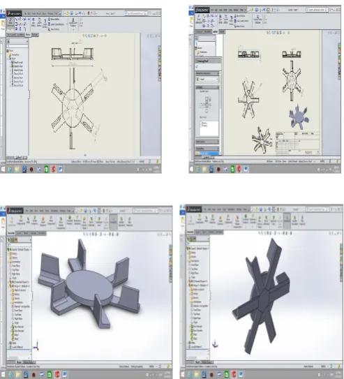
Before the construction of actual turbine, the design was simulated using solid works. Simulated model was generated in order to ease the fabrication of actual turbine. Following figures gives out the turbine design using solid works.
Fig -2: Micro turbine design using solid works
Fig -3: Micro turbine Blade Assembly
Fig -3: Micro turbine Casing
To design the turbine metal sheet is used. It is cut as per the required dimension and was used for making turbine blade (0.8mm thick) and casing (1 mm thick). Metal sheets are hard and weightless in comparison with iron sheet.
[image:2.595.321.548.93.325.2]The turbine and casing was constructed with the following dimensions:
Table -1: Design details of turbine
Sno Design part Dimension
1 Diameter of total wheel 30 cm
2 Wheel and blades thickness 8mm
3 Number of blades 8
4 Blade angle 40 degree
5 Shaft length 35 cm
6 Shaft diameter 15mm
7 Bearings 15mm
[image:2.595.36.283.241.513.2] [image:2.595.315.545.480.722.2] [image:2.595.64.265.542.731.2]© 2016, IRJET | Impact Factor value: 4.45 | ISO 9001:2008 Certified Journal | Page 469
3. MODELING OF HYDRO ELECTRO SERVO SYSTEM
Equations describing variation in flow and developed mechanical power with respect to the turbine speed, gate opening and runner blade movement of hydro turbine are considered for modeling of the system. The output power of turbine is reduced due to fall of pressure across the turbine. As the power developed in the turbine changes with the flow rate, the system operates or gains the steady state when the flow through the penstock gets constant.
The equations related to the transient performance of the hydraulic turbines are based on the following assumption.
(i) The hydraulic turbine`s blade is considered as smooth i.e. its frictional resistance is neglected.
(ii) The water hammer on penstock is neglected.
(iii) The fluid is considered as incompressible. (iv) The velocity of water in penstock varies
directly with gate opening.
(v) The developed output power of turbine is proportional to the product of head and velocity of flow.
Equation 1 and 2 represents the flow rate and the developed mechanical power at the shaft respectively in terms gate opening of the system and the net head.
Q=G√H --- 1
Where Q is Flow rate in m3/sec, G is gate opening in rad, H is net head in meter. The developed power, Pm in turbine can be written as
Pm=At H(Q-Qn1) --- 2
Where, At is the turbine gain, and Qn1 is the no load flow rate Velocity of water in Penstock “U” is given by
U=KU G√H --- 3 Ku is proportional constant.
Once the velocity of the water in penstock is determined, the relation of flow rate, head
Q=AU --- 4 The mechanical power output is given by
Pm = P – Pi --- 5
Where Pi is the fixed power loss in turbine due to friction.
Pi = UNLH --- 6 Where UNL stands for no load speed.
The hydraulic characteristics and mechanical power output of the turbine is modelled here. The nonlinear characteristics of hydraulic turbine are neglected in this model.
4. MATLAB/SIMULINK MODEL OF MICRO HYDRO
POWER PLANT ODELING OF HYDRO ELECTRO
SERVO SYSTEM
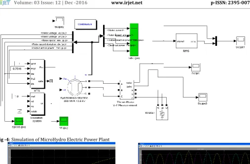
The individual sub-models like hydro turbine governor, synchronous generator, excitation system and 3-phase RLC load are now connected together to form the complete block diagram of micro hydro power plant shown in fig 4..
The simulation results obtained are shown in charts given below.
Chart -1: Vf per unit
© 2016, IRJET | Impact Factor value: 4.45 | ISO 9001:2008 Certified Journal | Page 470
Fig -4: Simulation of MicroHydro Electric Power PlantChart -3: Mechanical Power
Chart -4: Generated Voltage
Chart -5: Stator Current
[image:4.595.43.551.66.399.2]© 2016, IRJET | Impact Factor value: 4.45 | ISO 9001:2008 Certified Journal | Page 471
Chart -7: Output Power
Chart -7: RMS Value of voltage and current
5. CONCLUSIONS
A micro Hydro Electric Power Plant has been constructed successfully. In order to design the turbine solid works has been used as a design tool. A model of the turbine to be designed was drawn in the solid works. Actual turbine using the model developed in solid works was done by using metal sheet available in mechanical workshop. The turbine was designed with 8 blades using metal sheet of thickness 0.8mm. In order to avoid the splashing of water outside the turbine a case has been constructed using 1mm sheet. Two holes are provided in the casing for enabling inlet and outlet of water from the turbine. The micro model is simulated using the matlab and tested for its performance. At the outset the developed micro hydro electric power plant can be used to charge the battery that can be used in case of sudden power failure or an inverter can be designed to convert the generated DC to AC and can be used as standby power supply for motor room or for garden during night time.
ACKNOWLEDGEMENT
The mechanical design of this project was done at Nizwa College of Technology. The model is tested practically and validated for performance.
REFERENCES
[1] Auwal Abubakar Usman, Rabiu Aliyu Abdulkadir,
“MODELLING ANDSIMULATION OF MICRO HYDRO POWER PLANT USING MATLAB SIMULINK”, International Journal of Advanced Technology in Engineering and Science, Vol.No.3, Issue 1, September 2015.
[2] http://www.hydroquebec.com/learning/hydroelectricit
e/types-turbines.html
[3]
http://www.instructables.com/id/Making-Turbine-blades-on-solid-works/
[4] Feasibility Study of Hydro electric System for
Application in Amhara Region, Ethiopia, 2010.
[5] Technical Analysis of Hydro Electric Power and
Integration with Wind Power in the Pacific Northwest, August 2009