© 2017, IRJET | Impact Factor value: 6.171 | ISO 9001:2008 Certified Journal | Page 1564
Design of Steering Gear System in Passenger Car: A Review
Rayappa Mahale
1, Mohit Jaiswar
2, Gaurav Gupta
3, Abhishek Kumar
41
Assistant Professor, Department of Mechanical Engineering, D Y Patil Technical Campus, Ambi, Pune.
2,3,4
UG Student, Department of Mechanical Engineering, D Y Patil Technical Campus, Ambi, Pune.
---***---Abstract -
rack and pinion steering systems are commonlyused due to their simplicity in construction and compactness. The main purpose of this paper is to design and manufacture manual rack and manual pinion steering system according to the requirement of the vehicle for better manoeuvrability. Quantities like turning circle radius, steering ratio, steering effort, etc. are inter-dependent on each other and therefore there are different design consideration according to the type of vehicle. The comparison of result is shown using tables which will help to design an effective steering for the vehicle. A virtual rack and pinion assembly can be created using software’s like SOLIDWORKS and ANSYS.
Keywords
: Ackerman Steering Geometry, Motiontransmission, Rack and Pinion Housing and Tie Rod Assembly.
1. INTRODUCTION
Steering is the term applied to the collection of components, linkages, etc. which will allow a vessel (ship or Boat) or vehicle to follow the desired course. An exception is the case of rail transport by which rail tracks combined together with railroad switches provide steering column, which may contain universal joints, to allow it to deviate somewhat from a straight line.
The most conventional steering arrangement is to turn the front wheels using a hand–operated steering wheel which is positioned in front of the driver.
The steering system acts a significant role of making car convenient to handle and enhance the vehicle stability. In the past one hundred years, the development of steering system has experienced many stages, and the Steer-by-Wire system (SBW) is the newest technology of steering system for passenger cars. But the Steer-by-Wire system has not yet accepted by public consumers and permitted by state regulations, in consideration of the reliability and safety of the system.
The steering system of a vehicle allows the driver to control the direction of the vehicle through a system of gears and linkages that connects the steering wheel with the front wheels. Steering Systems - Introduction The steering system must perform these functions:
• Change direction of vehicle.
• Provide a degree of 'feel' of the road for the driver.
• Not transmit excessive shock back to the driver due to an uneven road.
• Not cause excessive tire wear.
1.1 CONVENTIONAL STEERING SYSTEM
In this steering system, only the front wheels are steered towards right or left according to the requirement because at the rear their dead axle is present.
1.2 FOUR WHEEL STEERING SYSTEM
In this steering system, the all four wheels are to be steered according to the steer perform to drive towards left or right. Four-wheel steering, also called rear-wheel steering or all-wheel steering, provides a means to actively steer the rear wheels during turning maneuvers. It should not be confused with four-wheel drive in which all four wheels of a vehicle are powered. It improves handling and helps the vehicle make tighter turns. Production-built cars tend to under steer or, in few instances, over steer. If a car could automatically compensate for an under steer/over steer problem, the driver would enjoy nearly neutral steering under varying conditions.
In most active four wheel steering system, the rear wheels are steered by a computer and actuators, the rear wheels generally cannot turn as far as the front wheels. Some systems including Delphi’s Quadra steer [3] and the system in Honda’s Prelude line allow the rear wheels to be steered in the opposite direction as the front wheels during low speeds. This allows the vehicle to turn in a significantly smaller radius sometimes critical for large tucks or tractors and vehicles with trailers
.
1.3 ACKERMAN STEERING SYSTEM
According to Ackermann Steering geometry, the outer wheels moves faster than the inner wheels, therefore, the equation for correct steering is [8]:
© 2017, IRJET | Impact Factor value: 6.171 | ISO 9001:2008 Certified Journal | Page 1565 In the image shown below,
Φ = outer wheel angle θ = inner wheel angle b = track width L = wheelbase α = Ackermann angle
2. STATEMENT OF THE PROBLEM
In conventional steering system we use the Ackermann geometry this is the arrangement of linkages in the steering of a car or other vehicle designed to solve the problem of wheel on the inside and outside of a turn needing to trace out circles of different radii.
In Anti-Ackermann geometry at low steering ratio and at high speed, handling capacity is low to eliminate this drawback we use the Ackermann geometry. In Ackermann geometry high speed handling increases and reduces the condition of over-steer and the vehicle handling capacity increases.
3. OBJECTIVES
The function of the steering system is clearly to afford the driver directional control of the vehicle, and to provide this control with sufficient accuracy to choose the best course around corners, to avoid other vehicles and stationary obstructions, and to maneuver the car efficiently at low speed. The following parameters need to be designed to minimize the steering effort.
1. Design of Steering arm angle. 2. Design Steering arm length.
3. Optimize Rack Position and placement of rack.
4. Optimize Steering effort, this factor should be designed according to wheel base and wheel track of the vehicle. 5. To study various wheel alignment related issues.
6. To understand the steering system in an automobile.
7. To study the components of steering systems and their configurations.
4. LITERATURE REVIEW
Rudolph Ackermann invented the steering mechanism allowing the vehicle to turn along the flow of the path in early 1800’s, called as Ackermann steering. The parallelogram steering mechanism was developed in late 1800’s. The major studies performed on the steering mechanisms and steering geometry optimizations are:
Sr.No Author Work Year
1.
Hardikkumar Gadher, Tejashkumar
Patel, Chirag Modi
Zeel Bhojani Chandubhai S Patel Institute of Technology,
CHARUSAT, Gujarat, India.
2017
2. Mohammad Kristamto
“Measuring geometric and kinematic properties to design steering axis to angle turn of the electric golf
car.”, International Conference on Sustainable Energy
Engineering and Application.
2015
3. R.S. Khurmi, J.K. Gupta “Theory of Machines”, S Chand & Company Pvt.
Ltd., Vol 1, 14th Edition, 2014
4. S.K. Gupta
“A Textbook of Automobile Engineering”, S. Chand
& Company Pvt. Ltd., Vol 1, 1st Edition,
2014
5.
Saket Bhishikar,
Vatsal Gudhka, Neel Dalal, Paarth Mehta, Sunil
Bhil, A.C. Mehta
“Design and Simulation of4 Wheel Steering System”, International
Journal of Engineering and Innovative Technology
(IJEIT), Volume 3, Issue 12,
June 2014
6. Dr. Kirpal Singh Engineering”, Volume 1, “Automobile 2013
1. Design and Optimization of Steering System, Hardikkumar Gadher, Tejashkumar Patel, Chirag Modi, Zeel Bhojani Chandubhai S Patel Institute of Technology, CHARUSAT, Gujarat, India. 2017
2. Mohammad Kristamto - “Measuring geometric and kinematic properties to design steering axis to angle turn of the electric golf car.”, International Conference on Sustainable Energy Engineering and Application. 2015
© 2017, IRJET | Impact Factor value: 6.171 | ISO 9001:2008 Certified Journal | Page 1566 4. S.K. Gupta - “A Textbook of Automobile Engineering”, S.
Chand & Company Pvt. Ltd., Vol 1, 1st Edition, 2014
5. Saket Bhishikar, Vatsal Gudhka, Neel Dalal, Paarth Mehta, Sunil Bhil, A.C. Mehta - “Design and Simulation of 4 Wheel Steering System”, International Journal of Engineering and Innovative Technology (IJEIT), Volume 3, Issue 12, june 2014
6. Dr. Kirpal Singh, “Automobile Engineering”, Volume 1, 2013
5. MATERIALS SELECTION
The materials used in the steering system target precise operation and light weight components. Although precision and weight are the top priorities, cost, manufacturability, and reliability were also considered. Precision in the steering system is derived from high manufacturing tolerances and minimal deflection. Deflection in any component leads to steer compliance, resulting in an unresponsive steering system.
The pinion and idler gears were purchased, which limited material options but reduced manufacturing time. Although these gears are steel, they have a smaller face width than a comparable aluminium gear. The rack gear is Turned, Ground and Polished (TGP) 1042 carbon steel rod [4]. The TGP material is more precise than standard round stock and the TGP finish removes surface tension inherent from standard extruding. This reduced the risk of the rack gear bending when the gear teeth were cut. The higher strength of the steel also allowed for extra material to be removed without introducing steer compliance. In addition to the precise material, the steel on steel gear mesh is advantageous for reliability. A softer material in the gear mesh would increase the possibility of galling, and compromise precision over time.
5.1 CHEMICAL COMPOSITION OF MATERIALS
EN-19 EN-24 7075-Al ALLOY Carbon
0.35-0.45 C 0.36-0.44 Al 87.1-91.4 Manganese
0.50-0.80 Mn 0.45-0.70 Mn 0.3 Silicon
0.10-0.35 Si 0.10-0.35 Si Max. 0.4 Nickel
--- Ni 1.3-1.7 Zn 5.1-6.1 Molybdenum
0.20-0.40 Mo 0.2-0.35 Cu 1.2-2.0 Chromium
0.90-1.50 Cr 1.0-1.4 Cr 0.18-0.28 Sulphur
0.05 S 0.04 Fe Max 0.5 Phosphorous
0.05 P 0.035 Mg 2.1-2.9 Table.1.
5.2 MECHANICAL PROPERTIES OF MATERIAL WITH
REFERENCE TO HEAT TREATMENT PROCESSES
(EN–19)
Forging
Pre heat carefully, then raise temperature to 850-1200°C for forging. Do not forge below 850°C. After forging cool slowly in air.
Annealing
Heat the EN19T slowly to 680-700°C. Cool in air.
Hardening
This steel grade is commonly supplied ready heat treated. If further heat treatment is required annealed EN19 should be heated slowly to 860-890°C and after adequate soaking at this temperature quench in oil. Temper as soon as tools reach room temperature.
Tempering
Heat carefully to a suitable temperature selected by reference to a tempering chart or table. Soak at the temperature for 2 hours per 25mm of ruling section, and then allow to cool in air. Tempering between 250-375°C is not advised as tempering within this range will reduce the impact value.
Heat Treatment
Heat treatment temperatures, including rate of heating, cooling and soaking times will vary due to factors such as the shape and size of each steel component. Other considerations during the heat treatment process include the type of furnace, quenching medium and work piece transfer facilities. Please consult your heat treatment provider for full guidance on heat treatment of EN19T alloy steel.
5.3 APPLICATION
EN19T was originally introduced for the use in the machine tool and motor industries for gears, pinions, shafts, spindles and the like. Later its applications became much more extended and it is now widely used in areas such as the oil and gas industries. EN19T is suitable for applications such as gears, bolts, studs and a wide variety of applications where a good quality high tensile steel grade is suited.
© 2017, IRJET | Impact Factor value: 6.171 | ISO 9001:2008 Certified Journal | Page 1567 is essential part of any engineering activity.
Mechanical test is applied to the materials, components and assemblies. It consists of measurement of fundamental properties or measurement of responses to particular influences such as load5, temperature, etc. Types of mechanical tests carried out in EN19 (AISI4140) material are tensile test, Impact test and Hardness test. Table 1. shows the chemical composition of the material.
6. CALCULATIONS
The geometry validation was done by performing the analytical treatment. The concept of reverse engineering was applied in order to validate the designed geometry.
The following calculations were performed in order to validate the geometry [1]:
Required conditions are:
6.1 ACKERMANN GEOMETRY
Angle of inside lock (θ) = 300
According to Ackermann Geometry for perfect steering is given by:
Cot Φ – Cot θ = b / l Cot Φ =Cot θ + b / l Cot Φ = Cot (30) + 1260/2032
Hence rearranging and substituting values in above equation;
(Φ) = 23.020
Also,
Inner Turning Radius, (Rif) = l/sin θ = 2032/ sin (30)
(Rif) = 4064 mm
Outer Turning Radius,
(Rof) = l/sin Φ = 2032/sin (23.02)
(Rof) = 5196.2 mm
Hence by comparing both graphical and analytical data we can conclude that the both values are converging thus, the system design is accurate.
CATIA Model of Steering Angle Geometry
6.2 SELECTION OF GEAR TOOTH PROFILE
A gear tooth profile was selected based on BIS (Bureau of Indian Standard) recommendation and the manufacturability. A 200 full depth involute profile system
was selected because of the following advantages:
It reduces the risk of undercutting It reduces the interference
Due to increase in pressure angle, the tooth becomes slightly broader at the root this makes the tooth stronger and increases its load carrying capacity. It provides better length of contact.
The properties of teeth of 200 full depth involute profile
system are as follow:
Minimum number of teeth on pinion:
The minimum number of teeth required on pinion in order to avoid the interference was computed using following relation:
Zp = 2ha/m.sin2Φ
Substituting values in above equation;
Zp = 2ha/m.sin2Φ
= 2/ sin2Φ
Zp =17.09=18
Hence minimum numbers of teeth on pinion are: 18.
Some other details of gear teeth profile are given below,
Module = 2
20° full depth involute system ɸ =20° Addendum = ha = 1m = 2mm
Dedendum = hf = 1.25m = 2.5mm
Clearance = C = 0.25m = 0.5mm Working Depth = 2m = 4mm Whole Depth = 2.25m = 4.5mm Tooth thickness = 1.5708m = 3.14mm
6.3 STEERING RATIO
The steering ratio is the ratio of how much the steering wheel turns in degrees to how much the wheel turns in degrees.
Approximating maximum turn to be of 25 degrees and steering wheel movement to be 180 degrees the steering ratio can be calculated as,
S.R =180/25 =7.2
6.4 RACK TRAVEL
© 2017, IRJET | Impact Factor value: 6.171 | ISO 9001:2008 Certified Journal | Page 1568 The steering wheel decided is AIM Formula steering wheel 2
which has a radius of 130 mm.
The steering wheel travel for one complete rotation,
=2π x r =0.6911m
Considering maximum steer angle and max rack travel is reached at complete rotation of the steering wheel.
The steering ratio can be equated to steering wheel travel/rack travel
7.2=0.6911/Rack travel Rack travel=95.98 mm
Therefore, required rack travel is around 96 mm.
6.5 RACK POSITION
The rack can have two positions. It can either be in front of the front wheel center line or behind it. If the rack is placed forward of the front axle line it can be mounted easily on the frame giving wide range for choice of heights. However, this arrangement makes it difficult to have the steering rack, track rods and steering arms in a straight line which is required if Ackermann geometry is a goal for steering design. Fixing the rack behind the axle line is better from both a geometrical and packaging viewpoint. Hence it is decided to have the rack positioned behind the front axle line i.e. a rear steer is chosen.
7. DESIGN AND ANALYSIS
We are using rack and pinion mechanism because of oblivious advantages of reduced complexity, ease of construction and less space requirement compare to other steering mechanisms. The analytical steps involved in designing if rack and pinion systems are as follow:
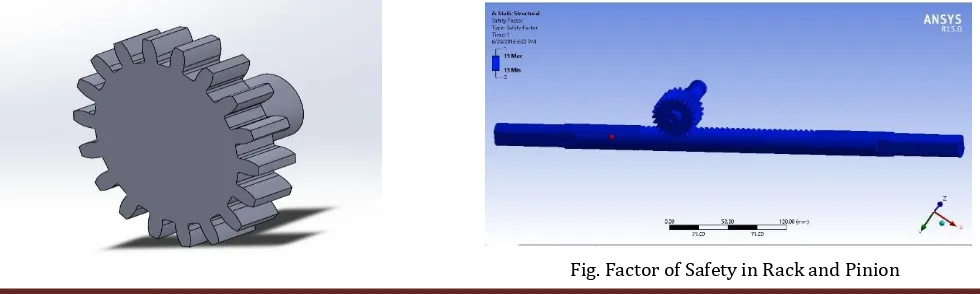
7.1 CAD MODEL OF RACK AND PINION
[image:5.595.261.555.52.204.2]We have designed complete assembly of rack and pinion in SOLIDWORKS 2015, the complete design of rack and pinion and its assembly in SOLIDWORKS 2015 is shown below:
Fig. Cad model of Rack and Pinion in SOLIDWORKS
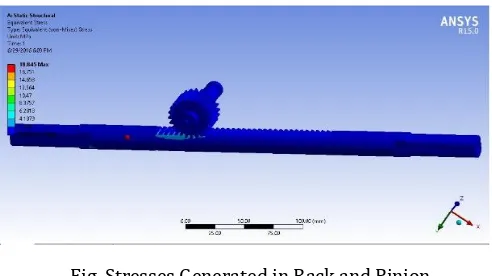
7.2 ANALYSIS OF COMPONENTS
Analysis is process of analysing the components by applying load, temperature, pressure etc. and obtaining the values such as stresses (bending, tangential and normal), deformations, safety factor etc. in order to determine the safety of the components when done in practical. These Analyses gives optimum result of safety of components and minimize the chances of failure.
Three major analyses of rack and pinion on Ansys 15.0 are carried out here [8]:
1) Total Deformation 2) Equivalent Stress 3) Factor of Safety
[image:5.595.309.557.445.580.2]a) Total Deformation
Fig. Total Deformation in Rack and Pinion
b) Factor of Safety
[image:5.595.66.556.632.779.2]© 2017, IRJET | Impact Factor value: 6.171 | ISO 9001:2008 Certified Journal | Page 1569 c) Equivalent Stress
Fig. Stresses Generated in Rack and Pinion
Material Type: EN 19 Alloy Steel
Thus after the analyses of components The Design is Completely Safe.
8. SCOPE
An innovative feature of this steering linkage design is its ability to drive all four Wheels using a single steering actuator. Its successful implementation will allow for the development of a four-wheel, steered power base with maximum maneuverability, uncompromised static stability, front- and rear-wheel tracking, and optimum obstacle climbing capability.
The advanced system of “Four wheel steering” will work electronically with the help or microprocessors.
The system will utilize an onboard computer to control and direct the turning left and right of the rear wheels.
One of the big challenges in moving to steer-by-wire is, Seeger said, communications. That's right: The internal network. Because a steer-by-wire system has no mechanical connection between the steering wheel and the front wheels, instead of creating a system that is fail-safe, one that is fault-tolerant is needed: If something goes wrong, the system still operates. This means data redundancy is the system. "Rather than the CAN communications that we used today, we need something like Flex Ray to allow high-speed communications between the components." So there is a bandwidth issue. And, of course, higher power requirements. "Today with electric power steering, the driver inputs some torque and we multiply it. With steer-by-wire, 100% of the effort to steer the vehicle has to come from the electric motor."
9. CONCLUSION
To improve the steering geometry i.e. Ackerman geometry, which helps the driver to avoid the negative effect of cornering forces acting on the vehicle & increases the space in cockpit area and the comfort of driver. Steering geometry can be optimized by using mathematical model for
Ackerman condition for different inner wheel angles and select geometry for which percentage Ackermann as well steering effort is optimum. The composite material increases the strength of rack & pinion & reduces the weight of system which helps to reduce gross weight of vehicle. The weight Composite Material is reduced as compared to others material which is turn result in improved power transmission which overall improve the efficiency of the system.
Geometry Ackermann geometry Steering type Rack & Pinion Type of rack used Right sided mounted
Steering ratio 7.2:1 Inner turning radius 4064 mm Outer turning radius 5196 mm Inner wheel angle 30 degree Outer wheel angle 23 degree Steering wheel travel 360 degree (691 mm)
Rack Travel 96 mm Toe in (+ve) 1 degree Camber angle 0 degree Turning Radius 3.6 meter Material for Rack and
Pinion EN-19
Material for Steering
column MS
Steering results at a glance
REFERENCES
[1] Reza N. Jazar Vehicle Dynamics: Theory and Applications Springer 2008.
[2] Bhushan Akhare1, Sanjeev S Chouhan2, Performance & Value Analysis of Power Steering System, ISSN 2250-2459, Volume 2, Issue 8, August 2012.
[3] Dipalkumar Koladia Mathematical Model to Design Rack and Pinion Ackerman Steering Geometry, International Journal of Scientific & Engineering Research, Volume 5, Issue 9, September-2014 ISSN 2229-5518.
[4]Analysis of Mechanical Properties of En19 Steel Used in rack and pinion, N.V Diwakar, C. Bhagyanathan and J. David Rathnaraj Manufacturing Engineering Department, Sri Ramakrishna Engineering College, Coimbatore.
© 2017, IRJET | Impact Factor value: 6.171 | ISO 9001:2008 Certified Journal | Page 1570 [6] 2.Milliken, W.F. & Milliken, D. L. 1995, Race Car vehicle
dynamics, SAE International, Warrendale, PA USA. 7. 3.“The Automotive Chassis”,Prof. Dipl.-Ing. Jörnsen Reimpell, DiplIng. Helmut Stoll, Prof. Dr.-Ing. Jürgen W. Betzler; Great Britain by Biddles, Guildford & Kings Lynn; Second edition.
[7] Design and Optimization of Steering System, Hardikkumar Gadher, Tejashkumar Patel, Chirag Modi, Zeel Bhojani, Chandubhai S Patel Institute of Technology, CHARUSAT, Gujarat, India.2017
[8] Design and Simulation of Manual Rack and Pinion Steering System, Prashant L Agrawal, Sahil Shaileshbhai Patel, Shivanshu Rajeshbhai Parmar Department of Automobile Engineering Department of Mechanical Engineering L.J institute of engineering and technology. 2016.
BIOGRAPHIES
Rayappa Mahale received Bachelor’s degree in Industrial and Production Engineering and Master’s degree in Production Management from Visvesvaraya Technological University, Belgaum, Karnataka. Presently working as Assistant Professor in department of Mechanical Engineering at D. Y. Patil School of Engineering Academy, Ambi, Pune, India. His areas of interests are Lean Manufacturing, Industrial Robotics, Advanced Ergonomics, Mechatronics, Micro Fabrication and MEMS.
Jaiswar Mohit Kumar is now pursuing his Bachelor of Engineering in Mechanical Engineering at D. Y. Patil School of Engineering Academy, Ambi, Pune. He is presently working on the project of Design and Fabrication of Electric Solar Vehicle organized by Imperial Society of Automotive Engineers, Delhi.
Gaurav Gupta is now pursuing his Bachelor of Engineering in Mechanical Engineering at D. Y. Patil School of Engineering Academy, Ambi, Pune. He is presently working on the project of Design and Fabrication of Electric Solar Vehicle organized by Imperial Society of Automotive Engineers, Delhi.