Enhancement of Control Signal Using a Modified
Parallel PID Controller
Abdalla Milad Faraj
1,*, Abdulgani Albagul
1, Muhammad Abdulla Muhammed
21Department of Control Engineering, College of Electronic Technology, Bani Walid, Libya 2Higher Institute of Medical Technology, Bani Walid, Libya
Copyright©2018 by authors, all rights reserved. Authors agree that this article remains permanently open access under the terms of the Creative Commons Attribution License 4.0 International License
Abstract
Control system is a collection of elements and operations that works together to accomplish a unique task, which are measurement, control, and actuating. A good performance of this system is based on a good signal transmitting between their components. One of these main signals is called “control signal”, which actuate the actuator to perform the control task. Due to some limitation of the actuator; the problem attended with the control action is how to keep it within the actuator limits to avoid the nonlinearity saturation phenomena. Therefore to achieve the high performance of the system, the control signal (control action) should be regulated instantaneously with the process output (stability of the system) in control system design. This paper presents simulating two cases of study, which are temperature and level control processes. These processes are controlled by a parallel PID controller and applying some modification techniques that are used to enhance the control signal which is essentially to fortify the actuator from the saturation phenomena. The modification techniques are based on repositioning the controller terms of the conventional parallel PID structure without any change in the tuned controller parameters. The outcome of the paper will help interested researchers in the control engineering area to select a suitable PID structure to design a perfect control system.Keywords
Control Signal, Parallel PID, Modification1. Introduction
A Proportional–Integral–Derivative (PID) controller is a three-term controller that has a long history in the automatic control field starting from the beginning of the last century. Owing to its intuitiveness and its relative simplicity, in addition to satisfactory performance which is able to provide with a wide range of processes, it has become in practice the standard controller in industrial settings. It has been evolving along with the progress of
the technology and nowadays it is very often implemented in all kinds of control equipment [1-5]. The success of the PID controllers is also enhanced by the fact that they often represent the fundamental component for more sophisticated control schemes that can be implemented when the basic control law is not sufficient to obtain the required performance or a more complicated control task is of concern. The PID controller has several important functions: it provides feedback; it has the ability to eliminate steady state offsets through integral action; it can anticipate the future through derivative action. In process control, more than 95% of the control loops are of PID type, most loops are actually PI control [6]. PID controllers have survived many changes in technology ranging from pneumatics to microprocessors via electronic tubes, transistors, integrated circuits. The microprocessor has had a dramatic influence on the PID controller. Practically all PID controllers made today are based on microprocessors. This has given opportunities to provide additional features like automatic tuning, gain scheduling, and continuous adaptation. PID control remains an important control tool for three reasons: past record of success, wide availability and simplicity in use. These reasons reinforce one another, and from other hand, the requirements on a control system may include many factors, such as response to command signals, insensitivity to measurement noise and process variations, and rejection of load disturbances. The design of a control system also involves aspects of process dynamics, actuator saturation, and disturbance characteristics. It may seem surprising that a controller as simple as the PID controller can work so well. The general empirical observation is that most industrial processes can be well controlled with PID control provided that demands on the performance of the control are not too high [7].
2. Practical Parallel PID Problems
with two signals only, these signals namely called control signal and the measured output or the output response. This paper devoted to discuss how to achieve acceptable output by applying acceptable control signal. On other hand the general relation between the controller part and the plant in the control loop implementation is illustrated in Figure 1.
[image:2.595.304.535.81.249.2]Figure 1. The controller and the process connection As shown from Figure1, the first part of the plant called an actuator or final control element which receive the control signal from the controller and adjust the output to keep it at the desired value of the control system, physically many problems occurs at the controller and actuator connection. In the parallel PID form shown in Figure2. These problems are related with its blocks or components which can be summarized in the following sections.
Figure 2. Parallel PID blocks
A. Proportional Kick
Proportional kick is the term given to the observed effect of the proportional term in the usual parallel PID structure on rapid changes in the reference signal. Using Figure 1, if the process is under control and the outputs Y(s) of the system are steady then the error signal E(s) will be close to zero. Consider now the effect of a step change in the reference input R(s) this will cause an immediate step change in the error and the controller will pass this step change directly into the controller output U(s) via the proportional term. Figure 3 shows output and control signals for this proportional kick problem [8].
Figure 3. Proportional kick [8]
In these circumstances, the actuator unit will experience a rapidly changing command signal that could be detrimental to the operation of the unit; the actuator will receive a proportional kick and gives it in saturation region.
B. Derivative Kick
[image:2.595.58.291.160.240.2]Derivative kick is very similar to proportional kick, if the output of the process is under control and steady then the set point error signal E(s) will be close to zero. A subsequent step change in the reference signal R(s) will cause an immediate step change in the error signal E(s). Differentiating a step change will produce an impulse-like spike in the control signal and this is termed derivative kick. Figure 4 shows typical output and control signals for this problem. Note the very sharp spike-like change in the control signal U(s). This control signal could be driving a motor or a valve actuator device, and the kick could create serious problems for any electronic circuitry used in the device [4].
[image:2.595.63.286.371.506.2] [image:2.595.309.535.497.674.2]3. PID Modification and Simulation
Results
In this section, two cases of study will be simulated and tested with various parallel PID control structure starting with the simplicity one of PID controller and the others are the modification forms of the basic parallel PID form. The step change has been applied to simulate the change of the reference or desired process output. The control signal and the output response will be discussed and compared between different controller structures.
3.1. Case Study 1 (Slow Dynamic Process): Temperature Control Process (Heating Tank Process)
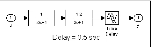
The mathematical model of the heating tank process is represented in the Simulink sub blocks as illustrated in Figure 5 [9].
By using signal builder block in MATLAB Simulink, the step change reference can be generated as shown in Figure 6. There are two step change levels, the first level starting at 5 sec with level equal to 1 unit and terminated at 40 sec, the second level starting at 40 sec with 2 units and terminated at 80 sec (Simulation duration).
[image:3.595.169.430.251.331.2]Figure 5. Simulink blocks of case study 1 (heating tank process)
Figure 6. Step change reference for heating tank simulation
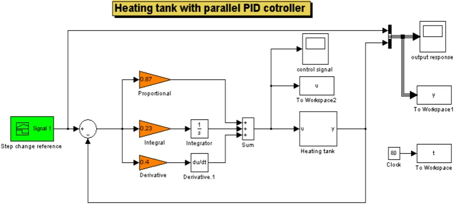
By using this step change and using the auto-tuning with MATLAB Simulink, the parallel PID controller parameters are defined by:
The proportional gain(KP = 0.87), the integral gain (KI = 0.23), and the derivative gain (KD = 0.4 ). These values of controller parameters which have been applied to the process model with different controller structure and the simulation results are summarized in the following sections.
[image:3.595.76.522.347.646.2]The block diagram of the closed loop of the heating tank controlled by the parallel PID controller is shown in Figure 7.
Figure 7. Simulink diagram of heating tank with parallel PID controller
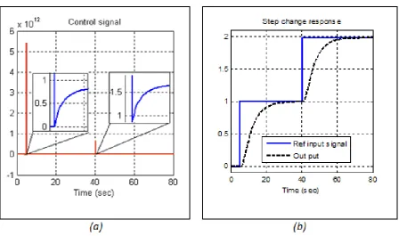
The control signal and the output response results for this case are illustrated in Figure 8 a and b respectively
Figure 8. The control signal and step change response of heating tank with parallel PID controller
[image:4.595.77.522.352.596.2]B. Modified PID Controller as ID&P Structure
[image:5.595.89.524.168.357.2]By using the same values of the controller parameters, the block diagram of the heating tank with ID&P structure is shown in Figure 9, and the simulation results using this kind of structure in shown in Figure 10 a and b. In this modification, also the kick phenomena is looked in the control signal but appeared in different behavior, and the change step response appeared in slow trend. Another controller form will be discussed to achieve different control actions related with different step change responses.
Figure 9. Simulink diagram of heating tank with ID&P structure
[image:5.595.75.524.380.645.2]C. Modified PID Controller as PD&I Structure
[image:6.595.77.521.133.317.2]To show the effect of connecting the integral term of PID controller with the measured output instead of error signal, the following Simulink diagram Figure 11 have been implemented.
Figure 11. Simulink diagram of heating tank with PD&I structure
[image:6.595.74.520.390.642.2]The resulting control signal and step change response of simulation the closed loop described by Figure 11 are shown in Figure 12 a and b respectively. From the stated figure, the output signal is in worst case, thus this modification of PID is not recommended
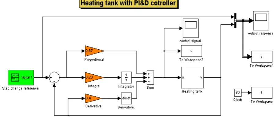
D. Modified PID Controller as PI&D Structure
[image:7.595.75.527.135.332.2]Another modification of PID controller is based on moving the derivative term to the feedback signal instead of error signal, this implementation illustrated in Figure 13.
Figure 13. Simulink diagram of heating tank with PI&D structure
Figure14 a and b shows both control signal and step change response with respect to step change reference with two step levels.
Figure 14. The control signal and step change response of heating tank with PI&D structure
E. Modified PID Controller as I&PD Structures
[image:8.595.75.527.140.335.2]This structure of PID controller used two control terms instead of one control term connected with the feedback signal in the previous structures. The choosing of these terms based on the simulation results of the previous structures, upon these results I&PD form have been selected as shown in Figure 15.
Figure 15. Simulink diagram of heating tank with I&PD structure
The simulation results of using I&PD structure of PID controller can be showed in Figure16 a and b
Figure 16. The control signal and step change response of heating tank with I&PD structure
Figure 16 shows clearly, there is no any kick phenomena on the control signal and this signal appeared in smooth form. From the other side the control signal is also appeared in acceptable response.
F. Comparative Assessments of Simulation Results of Heating Tank With PID Controller Modification
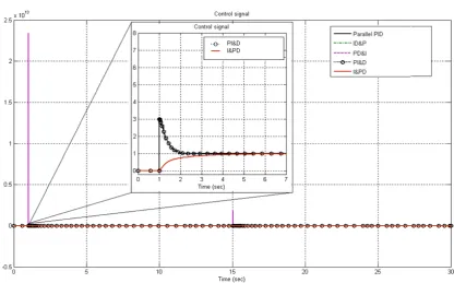
[image:8.595.73.522.369.595.2]Figure 17. Control signal comparative of parallel PID modification
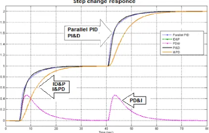
The step change responses are presented in the same graph as shown in Figure18. From this figure the output responses using parallel PID, and PI&D have a fastest responses compared with ID&P and I&PD. While in the case of using the PD&I controller structure, the output response is the worst.
According to the output responses shown in Figure18and the control signals in Figure17, the comparison will be done to show the influence of the control action with their output responses. The slowest step change response with good control action can be evaluated only at using I&PD controller structure. Meanwhile, PI&D provide acceptable control action with fastest step change responses.
[image:9.595.88.512.461.731.2]3.2. Case Study 2 (Fast Dynamic Process): Level Control Process (Double Tank Process)
To support the results that obtained in the previous case study; a double tank process will be selected as another case study which represented by the Simulink sub blocks as illustrated in Figure19 [1].
Figure 19. Case study 2 (Double tank process)
As the same manner, the reference step change can be generated as shown in Figure 20. Also the controller parameters of the parallel PID controller are tuned and regulated with MATLAB Simulink which defined as:
The proportional gain (KP = 3), the integral gain (KI = 2 sec-1), and the derivative gain (KD = 0.4 sec).
Figure 20. Step change reference for double tanks simulation
[image:10.595.170.430.132.222.2] [image:10.595.72.520.282.520.2]Figure 21. Step change responses of double tank with different PID structures
Figure 22. Control signals of different PID structures for double tank The general inspection of the simulation results of the
control signals and their step responses showed that the general shape of the control signals is similar with the results in the previous case study. In more details; this case study proved that, the integral term can't be applied in the
[image:11.595.89.503.80.389.2] [image:11.595.91.508.411.670.2]of I&PD form.
4. Conclusions
In this paper, the smooth control signal has been achieved from the parallel PID controller by repositioning the structure of its parameters. This study comes out from the existence of kick value in the control signal of parallel PID form when the set point is changed. The study was carried out using MATLAB Simulink to simulate heating tank process regulated by different suggested parallel PID control structures. The main advantage of the proposed modification techniques has been in the structures of the parallel PID form rather controller parameters, which are the critical issue in the controller design. However, the change is only done by repositioning the controller parts. Also the same tuning rules for the selection of the values of the PID parameters are available to the modified structures. According to the simulation results for the two cases of study, the control action does not depend on the kind of the process while the process behavior depends on the controller structure. The selection of a suitable PID structure depends on the desired specifications required by the designer or on the natural operation of the process. If the process required a fast control action and can tolerate some kick in the control signal then the parallel PID with filter and PI&D structures can be selected. Meanwhile, if the process cannot tolerate any kick and smooth control signal due to limitation of the actuator and can accept slow response then I&PD structure can be selected. It is believed that the conceptions of control presented in this paper will be of assistance in the adjustment of the existing controller applications and in the design of new installation.
REFERENCES
[1] Antonio Visioli, "Practical PID Control", Springer Verlag London limited, 2006.
[2] Indu Ramamurthi, "A Versatile Simulation Tool For Virtual Implementation of Proportional Integral and Derivative (PID) Controllers", Texas A&M University, May 2007. [3] David Sellers, "An Overview of Proportional plus Integral
plus Derivative Control and Suggestions for Its Successful Application and Implementation", 1st international conference for enhanced building operation, Texas, July 2001.
[4] Karl Johan Åström," Introduction to Control", Lund Institute of Technology, Sweden, 2004.
[5] Yun Li, Kiam Heong Ang, and Gregory C.Y. Chong "PID Control System Analysis and Design", IEEE Control Systems Magazine, P32-P41, February 2006.
[6] Karl J. Astrom and Tore Hagglund, "PID Controllers: Theory, Design, Tuning", 2nd Edition, Instrument Society of America, 1995.
[7] Karl J. Astrom and Tore Hagglund,"The future of PID control", Control Engineering Practice 9 (2001), P1163-P1175, Elsevier Science Ltd.
[8] Michael A. Johnson and Mohammad H. Moradi, "PID Control New Identification and Design Methods", Springer Verlag London limited, 2005.
![Figure 3. Proportional kick [8]](https://thumb-us.123doks.com/thumbv2/123dok_us/8751933.892091/2.595.304.535.81.249/figure-proportional-kick.webp)