Journal of Chemical and Pharmaceutical Research, 2014, 6(10):391-398
Research Article
CODEN(USA) : JCPRC5ISSN : 0975-7384The anchor craning beam support technology of the large section roadway
with compound roof
Zhao Mingzhou
1,2, Fang Juan
3, Chen Shanle
2, Hou Lidong
4and Fang Shizheng
41Faculty of Resources & Safety Engineering, China University of Mining & Technology(Beijing), Beijing, China 2
College of Mining Engineering, Guizhou University of Engineering Science, Bijie, Guizhou, China
3School of Civil Engineering, Guizhou University of Engineering Science, Bijie, Guizhou, China 4School of
Mechanics & Civil Engineering, China University of Mining & Technology(Beijing), Beijing, China
_____________________________________________________________________________________________
ABSTRACT
The routing of integrated circuits is an important procedure of the physical design after the layout. For this reason, an improved Field Programmable Gate Array (FPGA) routing approach is proposed based on the ant colony optimization. Experimental results suggest that the proposed approach is feasible and correct.
Key words: Field Programmable Gate Array; Routing Method; Ant Colony Optimization
_____________________________________________________________________________________________
INTRODUCTION
Much compound roof is composed of multi-thinner rock stratum which is filled with beddings, joints fractured, and this structure of weak coal seam roof in coal-bearing strata is widely distributed [1-2].The compound roof strata has low intensity, poor self-stability, joints fractured, and it contains much montmorillonite, kaolin and other ingredients, leading to water swelling, easily producing plastic deformation, and the physical and mechanical properties of the rock stratum are significantly different between the interlayer , moreover, the contact of the rock interlayer does not close , so the friction of them is small, leading to produce separation easily. In a word, the support of a large section roadway with complex roof is very difficult [3-4]. About more than one-third surrounding rock of coal roadway belongs to the weak compound roof in China, complex roof support is the key problem we facing when extending our coal mining to deep and stopping.
Zhang Lei etc[5] by using "high prestressed anchor cable + cable truss body" jointly controlled the compound mudstone roof to protect the stability of the roof support, and Fan Jian [6] used numerical simulation and field experiments to find that high strength prestressed anchor pole cable support systems can effectively control the complex roof roadway deformation and destruction in high stress deep mine, Yue Zhongwen, etc[7] according to the deformation and failure characteristics of the complex roof of large section roadways conducted similar simulation experiments and found that compound roof’s top and bottom angle prone to shear failure, causing the roof to increase the actual span, Bo Jianbiao [8] analyzed the damage characteristics of compound roof in extremely soft rock roadway, and proposed the use of grouting and bolting to control compound roof in extremely soft rock roadway, Gao Feng[9] pointed out that the deformation and failure of compound roofs is mainly associated with lack of bolt (Cable) initial preload, leading to the excessive amount of separation and deformation of the compound roof, He Bingyin[10] analyzed the compound roof anchor breaking conditions and reasons, Zou Hu[11] analyzed the influence of the compound roof span to the surrounding rock stability of coal roadways and proposed high-strength, high preload, high stability support ways, Li Weiteng etc[12] made theoretical and numerical analysis of four different arrangements of the pressure releasing cable box girder, Zhang Yongqing, etc[13] studied the deformation and failure characteristics of compound roof, and analyzed the supporting effect of the truss anchor girder.
technology, and also achieve fruitful results, but most studies are directed at relatively small sections of roadways, and lack of large roadway section research, especially the research of large roadway section deformation and failure characteristics under the anchor beam supporting. Taking the compound roof of the 11604 cut-hole large section roadway, a coal mine roadway in Guizhou, as the background, we analyse the support mechanism of anchor beam that supporting large section roadway, and apply the anchor beam support way in 11604 roadway. This research has important theoretical and engineering significance.
THE ANALYSIS OF ANCHOR BEAM MECHANISM IN LARGE SECTION WITH COMPOUND ROOF Anchor cable beam consists of high prestress cable and high stiffness joists, which are squeezed together to form a high strength and stiffness combined rock beam by prestress, so as to effectively control the roadway rock deformation and failure, its supporting schematic diagram shown in Figure 1 .
Toist
Anchor
Fig.1 Large section compound roof anchor beam supporting Schematic
(1) Joist squeeze in the upper strata under the action of anchor cable’s prestress, which change the roof strata from the unconformity contact rock strata under the unidirectional and bidirectional stress condition into a combination of three-dimensional stress state of the beam, while the horizontal joists anchor squeeze rock beams in horizontal and vertical direction, to increase strength and stiffness of rock beams.
(2) The joists in anchor beam supporting structure can greatly increase the surface area of the supporting structure, squeeze the compound roof strata under the action of high prestress, eliminate the gap between the support and the surrounding rock, so that the supporting structure can evenly bear deformation pressure of surrounding rock, preventing the support’s bearing capacity greatly reducing caused by uneven concentrated loads and eccentric loads, while the anchor can effectively spread in the roof.
(3) Rectangular roadway, especially in the large section roadway with compound roof, prone to shear failure, whose shoulder angle is the shear stress concentration area, and the effect of shoulder angle surrounding rock after destruction supporting roof weakens, causing the roof actual span increases, so that the rectangular roadway prone to cut the top and fall accident. The prestresse applied by Joist anchor that is through the shear stress concentration area, can offset some shear stress of the surrounding rock, and the anchor has a strong shear resistance, and can rock form anti- shear structure with beam, shoulder angle anchor together, which can effectively control shear failure of the shoulder angle.
THE DESIGN AND ANALYSIS OF COMPOUND ROOF SUPPORT PROGRAM IN LARGE SECTION ROADWAY
1 Project Overview
safety in production.
2 Design of support program
The section shape of 11604 cut-hole compound roof roadway is rectangular, its dimensions are: length × width = 7.0m × 3.2m, twice forming. The first excavation section size is 3.5m × 3.2m (width × height); and the second tunneling section size is 3.5m × 3.2m (width × height). Using anchor beams to support, the parameters are as follows:
Fig.2 Anchor beam support program
In the roadway roof we arrange 10 φ20mm × 2500mm L no longitudinal reinforcement high-strength steel bolt, the
inter-row space is 800mm × 800mm. The roof bolt distance of first tunneling section and the second section is 300mm, and every bolt anchor length is 1600mm, its tightening torque is not less than 140N • m. The angle of the roof corner bolt and the plumb line is 20 °, the rest of the roof bolt arranged vertically. Roof anchor support alternately arranged anchor joists and anchor monomer, the row spacing of anchor is 1.6m. When hitting a row of anchor joists, we hit a row of anchor monomer; the space of adjacent raw is 1.6m, the anchor in the first excavation roadway and the joist anchor in the second excavation roadway display in the same cross-section. Anchor
specifications is φ15.24mm × 10400mm, and the anchoring length is 3600mm, and the preload force is not less than
120kN. The distance of the anchor monomer to coal side is 1.8m, and the anchor beam bottom span is 2.0m, the distance of the anchor joists to coal side is 1.5m, the angle between the anchor joists and the vertical line is 20 °, and the angle between the anchor joists close to the roadway middle and the plumb line is 5 °, the joists using 12 # channel steel, the length is 2.0m.
Using φ20mm × 2500mm high strength steel bolt without longitudinal reinforcement support the roadway two
left-handed, anchoring length is 1.2m, tightening torque is not less than 100N • m, the row space between each anchor raw is 800mm × 800mm, and the distance of the upper side anchor to the roof is 400mm, and the angle between the upper side anchor and the horizontal direction is 10 °, the remaining three bolt arrange into a horizontal layout. The lower side anchor to the bottom is 400mm, the steel pallet specifications is 180mm × 180mm × 8mm (length × width × thickness), and using diamond wire mesh support surrounding rock, the metal mesh specifications
is: length × width = 11m × 0.85m. Steel ladder beams is welded by φ14mm steel bars, width 80mm and length 3.0m.
3 Numerical analysis of the support program
Fig.3 Rock stratum distribution in the model
Table.1 Coal and rock mechanical parameters
Lithology Density g/cm³ Shear modulus /GPa Bulk modulus /GPa Bond force /MPa Internal friction angle /(°) Tensile strength /MPa
Medium sandstone 2.63 12.5 16.5 14.15 31 9.1
Fine sandstone 2.60 11.1 14.7 8.58 30 3.53
Shaly sand 2.57 20.3 27.1 4.52 29 2.24
Mudstone 2.50 10.2 17.0 2.34 29 1.05
Coal 1.40 7.5 16.3 2.52 28 0.81
Table.2 Anchor and bolt mechanical parameters
Mechanical parameters Bolt Anchor
Elastic modulus 98.6GPa 150GPa
Tensile strength 600MPa 900MPa
Compressive strength 600MPa 900MPa
Resin stiffness 19MPa 19MPa
Resin cohesion 35MPa 35MPa
(b) Vector displacement of the anchor beam support
Fig.4 Vector displacement of the roadway
500
400
300
200
100
0
Former anchor net Anchor beam
Roof convergencesTwo sides move quantity Floor heaves
R
o
a
d
w
a
y
s
u
r
f
a
c
e
d
i
s
p
l
a
c
e
m
e
n
t
/
m
m
Fig.5 Surface displacement of the roadway
(b) Anchor beam support
Fig.6 Roadway plastic zone distribution
11604 cutting whole compound roof is composed of six mudstone and coal seam which is interactive occurrence, its strength is low, its span is large, and its overall stability is poor, and under the original anchor net support the roadway severely damages, as shown in Figure 6 (a). The numerical simulation results show that the greatest damage depth of the roof rock is 8.4m. After using the anchor beam support, the joists of the anchor beam increases the surface area of the support structure, so the Pre - tightening Force of the preload anchor in the roof get effective diffusion, effectively reducing the roadway roof rock tensile stress, and reducing the roadway roof strata damage extent, while the roadway compound roof in the anchoring range squeezed into a large rock beam which have large strength and stiffness, thus effectively controlling the roof deformation failure, as shown in 6 (b). The numerical simulation results show that under the anchor beam support the roof destruction depth reduced to 3.2m; as joists anchor pass through the roadway shoulder which is shear stress concentration area, the prestressing force the joists anchor produces can offset some of the rock shear stress, meanwhile the anchor has a strong shear resistance, so it can effectively control the shoulder shear failure, leading to reduce the plastic zone of the roadway two sides.
SITE MONITORING
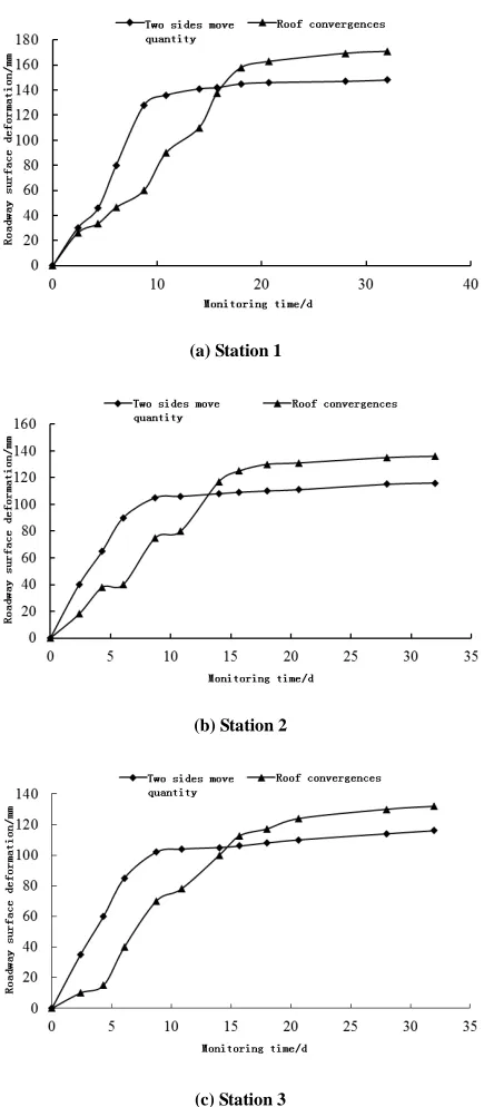
In order to observe the supporting effect of the anchor beams in cut roadway with the large section roadway compound roof, Surface displacement monitoring section is set using cross distribution point method ( as shown in Figure 7 ) and three stations are set in cut roadway with the large section roadway compound roof, the upper station is 35m away from the track crossheading, while the lower is 35m away from the transportation crossheading, the central station is located in the middle position of the cut roadway, the monitoring of changes in the roadway surface displacement as shown in Figure 8.
B
D
C
A
4
0
0
m
m
400mm
o
(a) Station 1
(b) Station 2
[image:7.595.200.422.72.569.2](c) Station 3
Fig. 8 Station roadway surface displacement
The change curve of the amount of roadway roof subsidence and side wall is divided into two stages in figure. Roof moves down on average at the rate of 7 ~ 8 mm/d in the initial roadway excavation and the roof goes into a stable deformation stage after 20 days, roof subsidence speed gradually reduces to 0.5mm/d, at this time the roof subsidence is 171mm; while two sides of roadway, on average, move at a speed of 15 mm/d early in the excavation, the deformation is gradually into the stable period after 12 days, and the speed of two walls closer is reduced to 0.5mm/d, at this time the amount of two walls closer is 148mm. Roadway surrounding rock control effect is better.
CONCLUSION
2) The support scheme is designed under the conditions of the anchor cable beam supporting combined with 11604 engineering geological conditions of the large section cut roadway with compound roof, and the characteristics of roadway deformation and failure are analyzed contrasting the anchor cable beam supporting with the original anchor wire rope supporting, using the method of numerical simulation. The results show that, roadway roof subsidence is reduced by 67.13% and the amount of two walls nearer is reduced by 58.72% under the condition of the anchor cable beam supporting.
3) Anchorage beam support technology is successfully applied in 11604the large section cut roadway with compound roof. The two sides and floor tends to be stable after roadway digging around ten days, while the roof is stable after 20 days later. The roadway roof subsidence is 171 mm, the amount of two walls nearer is 148 mm.
Acknowledgments
The authors are grateful to editors and anonymous referees for their very valuable comments and suggestions, which have significantly helped improving the quality of this paper. Meanwhile, this paper is supported by the Science and Technology Foundation of Guizhou Province (No. LKB [2012]03), Bijie College Fund Project for Scientific Research “Research on Stability and Support Strategies for Soft Surrounding Rock with Buried Depth Mutation” (NO.20112027).
REFERENCES
[1] Xue Yadong, Kang Tianhe. Journal of China Coal Society,2000,25(12):97-101. [2] Fang Bocheng. Coal Science and Technology,2007,35(7):8-12.
[3] Zhang Bin, Ren Yongjie, Han Xuefeng. Mine pressure and roof management 2002,2:81-84.
[4] Su Xuegui, Li Yanbin, Li Haochun. Journal of Taiyuan University of Technology (Social Sciences Edition), 2011,42(6):628-629.
[5] Zhang Lei,Zhang Zhiming,Zhai Ji, Etc. Coal Engineering, 2014,46(4):80-82. [6] Fan Mingjian. Coal Engineering, 2013, 11:30-33.
[7] Yue Zhongwen,Yang Renshu,Yan Zhendong, Etc. Journal of China Coal Society, 2006, 36:47-52.
[8] Bai Jianbiao, Hou Chaojiong, Du Mumin, Etc. Chinese Journal of Rock Mechanics and Engineering [J].2001,20(1):53-56.
[9] Yang Feng, Wang Lianguo, He Anmin, Etc. [J]. Journal of Mining & Safety Engineering, 2008,25(3):286-289. [10] He Bingyin. Coal Engineering, 2007,4:62-64.
[11] Zou Hu. Coal, 2013,22(9):45-47.