International Journal of Emerging Technology and Advanced Engineering
Website: www.ijetae.com (
ISSN 2250-2459,
ISO 9001:2008 Certified Journal,
Volume 3, Issue 8, August 2013)
657
Design and Implementation of an Efficient Gray Image
Compression technique Using Fuzzyfied Discrete Wavelet
Transform
Raju
1, Kailash C. Bandhu
2, Dileshwar Patel
31ATC, Indore (M.P.), 2Asst. Prof. ATC, Indore (M.P.),
3LNCT, Indore (M.P.)
Abstract- Images require substantial storage and transmission resources, thus image compression is advantageous to reduce these requirements. In the current scenario real time communication demands for fast, efficient processing as well as less storage of data, specially images and videos. The requirement of storage plays crucial role in real time application, which leads to requirement of efficient and fast compression techniques. For still image compression, the Joint Photographic Experts Group' or JPEG standard has been established by ISO (International Standards Organization) and IEC (International Electro-Technical Commission). Since then lots of work had been done on single channel image compression mostly using wavelet transform. But rapid growth in modern communication demands higher and higher compression ratio with smaller error. This arises the need of effective and standardized gray image compression technique. The aim of this paper is to develop and implement an algorithm for compression of single channel image i.e. gray images as well as to speed up the compression of multichannel images with high compression. This paper presents a new method of implementation of available wavelet transform based image compression technique for gray image compression using fuzzyfied discrete wavelet transform. Zadah in his first paper on fuzzy, discussed that fuzzy logic is an efficient tool for handlingimprecise and vague situations, hence fusion of fuzzy rule base with discrete wavelet transform is the Efficient way to achieve higher compression ratio with less error.
Keywords- Discrete Wavelet transform, color image compression, RGB color model.
I. INTRODUCTION
Image compression addresses the problem of reducing the amount of data required to represent a digital image. The underlying basis of the reduction process is the removal of redundant data. From a mathematical viewpoint, this is a process of transforming a 2-D pixel array into a statistically uncorrelated data set .The transformation is applied prior to storage or transmission of the image [1].
Currently image compression is recognized as an “enabling technology”. In addition to the areas just mentioned, image compression is the natural technology for handling the increased spatial resolution of today’s imaging sensors and evolving broadcast television standards. Furthermore image compression plays a major role in many important and diverse applications, including tele-video-conferencing, remote sensing (the use of satellite imagery for weather and other earth resource applications), document and medical imaging facsimile transmission (FAX) [2],[3], and the control of remotely piloted vehicles in military, space and hazardous waste management applications.
II. IMAGE COMPRESSION USING DISCRETE WAVELET
TRANSFORM
Wavelet Transform has become an important method for image compression. Wavelet based coding provides substantial improvement in picture quality at high compression ratios mainly due to better energy compaction property of wavelet transforms. Wavelet transform partitions a signal into a set of functions called wavelets. Wavelets are obtained from a single prototype wavelet called mother wavelet by dilations and shifting. The wavelet transform is computed separately for different segments of the time-domain signal at different frequencies.
2.1 Sub Band Coding:
A signal is passed through a series of filters to calculate DWT. Procedure starts by passing this signal sequence through a half band digital low pass filter with impulse response h(n).Filtering of a signal is numerically equal to convolution of the tile signal with impulse response of the filter.
International Journal of Emerging Technology and Advanced Engineering
Website: www.ijetae.com (
ISSN 2250-2459,
ISO 9001:2008 Certified Journal,
Volume 3, Issue 8, August 2013)
658
A half band low pass filter removes all frequencies that are above half of the highest frequency in the tile signal. Then the signal is passed through high pass filter. The two filters are related to each other ash[L-1-n]=(-1)ⁿg(n)………..(2)
Filters satisfying this condition are known as quadrature mirror filters. After filtering half of the samples can be eliminated since the signal now has the highest frequency as half of the original frequency. The signal can therefore be sub sampled by 2, simply by discarding every other sample. This constitutes 1 level of decomposition and can mathematically be expressed as
[ ] ∑ [ ] [ ]
[ ] ∑ [ ] [ ]…….. (3)
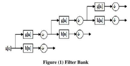
Where y1 [n] and y2 [n] are the outputs of low pass and high pass filters, respectively after sub sampling by 2. This decomposition halves the time resolution since only half the number of sample now characterizes the whole signal. Frequency resolution has doubled because each output has half the frequency band of the input. This process is called as sub band coding. It can be repeated further to increase the frequency resolution as shown by the filter bank.
Figure (1) Filter Bank
2.2 Compression Steps [9]:
1.Digitize the source image into a signal s, which is a string of numbers.
2.Decompose the signal into a sequence of wavelet coefficients w.
3.Use threshold to modify the wavelet coefficients from w to w’.
4.Use quantization to convert w’ to a sequence q. 5.Entropy encoding is applied to convert q into a
sequence e.
2.2.1 Digitation
The image is digitized first. The digitized image can be characterized by its intensity levels, or scales of gray which range from 0(black) to 255(white), and its resolution, or how many pixels per square inch [9].
2.2.2 Thresholding
In certain signals, many of the wavelet coefficients are close or equal to zero. Through threshold these coefficients are modified so that the sequence of wavelet coefficients contains long strings of zeros. In hard threshold, a threshold is selected. Any wavelet whose absolute value falls below the tolerance is set to zero with the goal to introduce many zeros without losing a great amount of detail.
2.2.3 Quantization
Quantization converts a sequence of floating numbers w’s to a sequence of integer q’s. The simplest form is to round to the nearest integer. Another method is to multiply each number in w’s by a constant k, and then round to the nearest integer. Quantization is called lossy because it introduces error into the process, since the conversion of w’s to q’s is not one to one function [9].
2.2.4 Entropy Encoding
With this method, a integer sequence q is changed into a shorter sequence, with the numbers in e being 8 bit integers The conversion is made by an entropy encoding table. Strings of zeros are coded by numbers 1 through 100,105 and 106, while the non-zero integers in q are coded by 101 through 104 and 107 through 254.
III. FUZZY DOMAIN
Fuzzy set theory is useful in handling various uncertainties in computer vision and image processing applications. Fuzzy image processing is a collection of different fuzzy approaches to image processing that can understand, represent, and process the image. It has three main stages, namely, image Fuzzyfication, modification of membership function values, and Defuzzification.
3.1 Fuzzy Image Processing
[image:2.612.59.275.449.559.2]International Journal of Emerging Technology and Advanced Engineering
Website: www.ijetae.com (
ISSN 2250-2459,
ISO 9001:2008 Certified Journal,
Volume 3, Issue 8, August 2013)
659
The representation and processing depend on the selected fuzzy technique and on the problem to be solved [3], [4]. Here is a list of general observations about fuzzy logic: Fuzzy logic is conceptually easy to understand.
Fuzzy logic is flexible.
Fuzzy logic is tolerant of imprecise data.
Fuzzy logic can be built on top of the experience of experts.
The basis for fuzzy logic is the basis for human communication. This observation underpins many of the other statements about fuzzy logic. Because fuzzy logic is built on the structures of qualitative description used in everyday language, fuzzy logic is easy to use [36], [37]. Fuzzy image processing has three main stages: image Fuzzyfication, modification of membership values, and, if necessary, image Defuzzyfication. Figure (2) shows the block diagram representation of Fuzzy Image processing.
Figure (2) Fuzzy Image processing.
The Fuzzification and Defuzzyfication steps are due to the fact that we do not possess fuzzy hardware. Therefore, the coding of image data (Fuzzyfication) and decoding of the results (Defuzzyfication) are steps that make possible to process images with fuzzy techniques. The main power of fuzzy image processing is in the middle step (modification of membership values).After the image data are transformed from gray-level plane to the membership plane (Fuzzyfication), appropriate fuzzy techniques modify the membership values [16]. This can be a fuzzy clustering, a fuzzy rule based approach, and a fuzzy integration approach and so on.
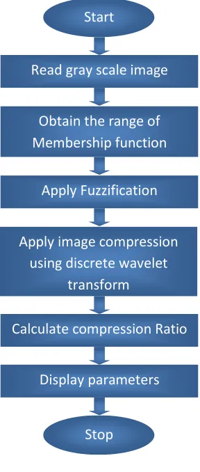
IV. METHODOLOGY
The proposed algorithm is based on the simple concept that, though the available Discrete wavelet transform is a single channel process, but it cannot able to provide higher compression ratio with less error.The basic idea of this paper is to enhance the compression ratio while keeping the error within a particular allowable range using fuzzy rule base system. The developed algorithm of the paper is discussed below step by step with the help of flow graph shown in the figure (5.1).
Figure (3) developed algorithm.
V. RESULT &DISCUSSION
The algorithm has been successfully developed and implemented in MATLB to develop an efficient gray image compression. Now we will show & discuss the various results obtained from the developed algorithm.
Start
Read gray scale image
Obtain the range of
Membership function
Apply Fuzzification
Apply image compression
using discrete wavelet
transform
Calculate compression Ratio
Display parameters
Stop
Expert Knowledge
Fuzzy Logic Set Theory
Res ult
Inp ut Im age
Membe rship Modific ation
Image Defuzzyfic
ation Image
[image:3.612.363.507.267.606.2] [image:3.612.51.273.365.535.2]International Journal of Emerging Technology and Advanced Engineering
Website: www.ijetae.com (
ISSN 2250-2459,
ISO 9001:2008 Certified Journal,
Volume 3, Issue 8, August 2013)
660
Since it is not possible to evaluate the performance of any algorithm on the basis of single image, hence for the performance evaluation of the developed algorithm two different gray images has been used. These images are shown in figure (4), figure (5) and figure (6). To compare the results obtained from the developed algorithm three most important image compression parameters viz, are used.1) Compression Ratio (CR). 2) Mean Square Error (MSE).
To show the compression and decompression process by using developed algorithm on first input image i.e. Autumn.tif. Whose size is 206X345 and memory requirement to store is 71070 bytes shown in figure (4). For the performance evaluation of developed algorithm on compression and decompression processes, the value of parameter level of decomposition is fixed to 5. The results obtained after the compression and decompression process using normal discrete wavelet transform (NDWT) and Fuzzyfied discrete wavelet transform (FDWT) are shown from figure (4.1), figure (4.2) and figure (4.3).
Figure (4.1) input image. Figure (4.2) Output image using (NDWT) Figure (4.3) Output image using (FDWT)
The compression parameters obtained after first input image compression and decompression process using NDWT and FDWT are as follows.
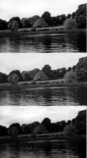
Similarly the results obtained for second input image ie. (lena.jpeg), who’s Size, is 415X445 and memory requirement to store is 180525 bytes are shown from figure (5.1) to figure (5.3). The compression parameters obtained after Second input image compression and decompression process using normal discrete wavelet transform (NDWT) and Fuzzyfied discrete wavelet transform (FDWT) are as follows.
S.No. Parameters Results for Normal DWT
Results for Fuzzyfied DWT
1 Bi (size of first input
image in bytes) 71070 bytes.
71070 bytes.
2
Bc (size of first compressed image in bytes)
10256 bytes. 7452 bytes.
3
Bo (size of first decompressed image in bytes)
71070 bytes. 71070 bytes.
4 Cr1 (Compression
Ratio) 8.526 76.2963
5
M.S.E1 (Between original &
decompressed Image)
[image:4.612.98.240.391.648.2]International Journal of Emerging Technology and Advanced Engineering
Website: www.ijetae.com (
ISSN 2250-2459,
ISO 9001:2008 Certified Journal,
Volume 3, Issue 8, August 2013)
661
Figure (5.1) input image. Figure (5.2) Output image using (NDWT) Figure (5.3) Output image using (FDWT)
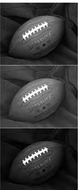
Again the results obtained for Third input image ie. (football.jpeg) Size 256X320 and memory requirement to store is 81920 bytes are shown from figure (6.1) to figure (6.3). The compression parameters obtained after Third input image compression and decompression process using normal discrete wavelet transform (NDWT) and Fuzzyfied discrete wavelet transform (FDWT) are as follows.
Figure (6.1) input image. Figure (6.2) Output image using (NDWT) Figure (6.3) Output image using (FDWT)
S.No. Parameters
Results for Normal DWT
Results for Fuzzyfied DWT
1 Bi (size of first input image in bytes) 180525 bytes. 180525 bytes.
2
Bc (size of first compressed image in bytes)
10256 bytes. 14298 bytes.
3
Bo (size of first decompressed image in bytes)
180525
bytes. 180525 bytes.
4 Cr2 (Compression Ratio) 15.896 101.0071
[image:5.612.101.237.135.489.2] [image:5.612.377.514.219.546.2]International Journal of Emerging Technology and Advanced Engineering
Website: www.ijetae.com (
ISSN 2250-2459,
ISO 9001:2008 Certified Journal,
Volume 3, Issue 8, August 2013)
662
VI. CONCLUSIONS
In this modern era during transmission and reception, the image storage plays very important and crucial role. In the present scenario the technology development wants fast and efficient result production capability. This paper presented an algorithm for real time gray image compression.
The developed algorithm is found very efficient for gray image compression. During the analysis it is found that, developed algorithm provides higher compression ratio as compare to normal discrete wavelet transform. In addition to this fuzzyfied discrete wavelet transform based developed technique is also able to keep error between input image and reconstructed image in allowable range, though it is generating slightly higher error but at the same time the compression ratio is much higher than available NDWT technique. The advantage of the developed algorithm is, Fuzzyfication performed before using DWT because normal DWT cannot able to handle imperfections presented in the input images.
REFERENCES
[1] Rao, K. R. and Yip, P., Discrete Cosine Transform: Algorithms, Advantages and Applications. San Diego, CA: Academic, 1990. [2] Gortler. S., Schröder, P., Cohen, M., and Hanrahan, P., "Wavelet
Radiosity", in Proc. SIGGRAPH, pp. 221-230, 1993.
[3] Berman, D., Bartell, J. and Salesin, D., "Multiresolution Painting and Compositing", in Proc. SIGGRAPH, pp. 85-90, 1994.
[4] Finkelstein. A. and Salesin, D., "MultiresolutionCurves", in Proc. SIGGRAPH, pp.261-268, 1994.
[5] Eck, M., DeRose, T., Duchamp, T., Hoppe, H., Lounsberry, M. and Stuetzle, W., "Multiresolution Analysis of Arbitrary Meshes", in Proc. SIGGRAPH, pp. 173-182, 1995.
[6] Lippert, L. and Gross, M., "Fast Wavelet Based Volume Rendering by Accumulation of Transparent Texture Maps", in Proc. EUROGRAPHICS, pp. 431-443, 1995.
[7] Jacobs, C., Finkelstein, A. and Salesin, D., "Fast Multiresolution Image Querying", in Proc. SIGGRAPH, pp. 277-286, 1995. [8] Andrew B. Watson NASA Ames Research Center “Image
Compression Using the Discrete Cosine Transform” Mathematica Journal, 4(1), 1994, p. 81-88.
[9] Ujjaval Y. Desai, Marcelo M. Mizuki, Ichiro Masaki, and Berthold K.P. Horn “Edge and Mean Based Image Compression” ARTIFICIAL INTELLIGENCE LABORATORY A.I.
Memo No. 1584 November, 1996.
[10] Carmen de Sola Fabregas, Nguyen Phu Tri “Ultrasound Image Coding using Shape Adaptive DCT and Adaptive Quantization” Proc. of the Conference on Medical Images, vol. 3031, 1997, p. 328-330 IEEE, 1997.
[11] F.G. Meyerand A.Z. Averbuchand J.O. Strombergand R.R. Coifman “Multi-layered Image Compression” 1998 International Conference on Image Processing (ICIP'98) Volume 2.
[12] David Taubman, Member, IEEE “High Performance Scalable Image Compression with EBCOT “IEEE TRANSACTIONS ON IMAGE PROCESSING, VOL. 9, NO. 7, JULY, 2000.
[13] Luciano Volcan Agostini, Ivan Saraiva Silva & Sergio Bampi“Pipelined Fast 2-D DCT Architecture for JPEG Image Compression” published in Integrated Circuits and Systems Design, 2001, 14th Symposium on.Publication Date: 2001On page(s): 226-231.
[14] RebeckaJornsten, Bin Yuy&Wei Wang, KannanRamchandranz “MICROARRAY IMAGE COMPRESSION AND THE EFFECT OF COMPRESSION LOSS” Science Direct, Signal Processing, Volume 83, Issue 4, April 2003, Pages 859-869.
[15] Emma SofiJonasson “Document Segmentation for Image Compression” A thesis submitted to Clayton School of Information Technology Monash University in November, 2005.
[16] NikolayPonomarenko, Vladimir Lukin,Karen Egiazarian and JaakkoAstola “DCTBased High Quality Image Compression” Proceedings of 14th Scandinavian Conference On Image Analysis, Joensuu, Finland, pp. 1177-1185, June, 2005.
[17] C. Kwan, B. Li, R. Xu, X. Li, T. Tran, and T. Nguyen “A Complete Image Compression Scheme Based on Overlapped Block Transform with Post-Processing” Hindawi Publishing Corporation EURASIP Journal on Applied Signal ProcessingVolume 2006, Article ID 10968, Pages 1–15 DOI 10.1155/ASP/2006/10968.
[18] Mr. T.Sreenivasulureddy Ms. K. Ramani Dr. S. Varadarajan Dr. B.C.Jinaga “Image Compression Using Transform Coding Methods” IJCSNS International Journal of Computer Science and Network Security, VOL.7 No.7, July 2007.
[19] Nileshsingh V. Thakur and Dr. O. G. Kakde “Color Image Compression with Modified Fractal Coding on Spiral Architecture” JOURNAL OF MULTIMEDIA, VOL. 2, NO. 4, AUGUST 2007. [20] Mark S. Drew and Steven Bergner “Spatio-Chromatic Decorrelation
for Color Image Compression” Image Communication, Volume 23 Issue 8.
S.No. Parameters
Results for Normal DWT Results for Fuzzyfied DWT 1
Bi (size of first input image in bytes) 81920 bytes. 81920 bytes. 2
Bc (size of first compressed image in bytes) 8990 bytes. 4810 bytes. 3
Bo (size of first decompressed image in bytes)
81920 bytes.
81920 bytes.
4 Cr2 (Compression
Ratio) 18.859 136.2495
5
M.S.E2 (Between original & decompressed Image)